Sale ends todayGet 30% off any course (excluding packages)
Ends in --- --- ---
Discussion and questions related to the course Practical Motorsport Wiring - Club Level
Hey Everyone!
I hope I find everyone in good spirits. I am hoping someone can shed some light on a few questions I have. I am at the point where I am planning the wiring that is going to go into the engine bay. I have reached the coils stage and it seems like people have different ways of wiring these things up. Now I have also heard horror stories about coils burning up and going up in smoke! My buddy actually had this happen to him. He didn't wire up his truck someone else did.
I am running an Adaptronic M2000 ECU along with AEM IGN1 Coils and a Hardwire Electronics PDM. Now traditionally I know people use relays and they run a 14ga wire and split this into 18ga wires for the coils. I bought a PDM to avoid using Relays and fuses. (As a side note I am using Tefzel M22759/32 wire on the whole project.)
Now for my questions: It really comes down to the grounds and the power supply. I've read so many different ways of grounding these things from grounding them exactly like how AEM suggest, to taking pins B, C, and D and grounding them to a single location on the block, to grounding them to the ECU to grounding them all to the negative post on the battery, etc, etc ... I am hoping that some of you guys with Rotary experience can chime in or maybe one of the guys from HPA can chime in and let us know how they wired up the coils on their project FD. As for what I was thinking was pin A is obviously the trigger signal from the Adaptronic ECU (22ga Wire) Pin B ground this from the Adaptronic (22ga wire) as I read that it is needed so the ECU can take correct readings. Pins C, and D (22ga wire) ground them to the knock sensor hole above the spark plug in the housing since that knock sensor is not being used anymore.
As for the 12v power source my plan was to wire an output from the PDM (18ga wire) and splice that into 4 (20ga wire) runs, one for each coil. I also plan to wire the ignition wire coming out from the ECU into an input on the PDM and use THIS to signal the PDM to power up the coils. So CAN Keypad button for ignition turns on ECU, ECU sends ignition signal back to the PDM which in turn activates the coils. That way the coils only turn on once the ECU turns on. Kind of like a safety feature. 😁 at least that is how I see it. As I said last thing I want is for these things to just go up in smoke just sitting there.
Anyway I hope my logic is on the right path. I am doing it wrong please let me know.
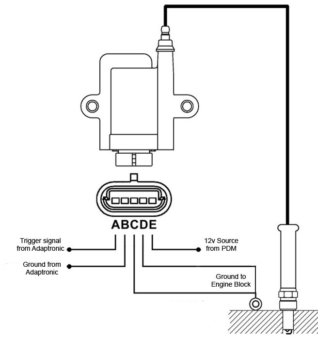
Hello i have had many of these wired and have always done it exactly the same as the diagram you have posted above
with great success
Thanks for the response Ross ... I feel better now knowing I am on the right path! 😁 This is my 1st time wiring up an EFI system.
So a little FYI ... I finally got a response back from Adaptronic after waiting for like a week. Their recommended setup for the AEM IGN1 is to ground B, C, and D to the block. Just thought I would share.
This question does get asked a lot since there are so many conflicting ways to go if u do a search on it. FWIW the general consensus is to wire the seperate grounds to ecu signal ground, battery and block as layed out in haltechs diagram, the 3 grounds are separate for a reason afterall. The way you originally had planned in my opinion is perfectly fine but there does seem to be potential for problems if tying the signal ground in with the rest of your grounds as adaptronic have recommended, it might be fine in some cases but people have had problems with it done that way


