Sale ends todayGet 30% off any course (excluding packages)
Ends in --- --- ---
Discussion and questions related to the course Practical Motorsport Wiring - Professional Level
Hi,
So in the process of wiring up a c1212 in a vehicle and have a question in relation to the ground required to the sender unit as the sender uses the body of the tank as it’s ground point.
Was going to run the signal to the temperature input but not sure if I should run the sensor ground to the tank also or will the tank ground point be sufficient? Concerns about back feeds to the sensor ground pin to the display or am I overthinking it?
Thanks in advance
Corrado
+1
I would start with not connecting the 0V to the ground at the fuel tank. You will probably be OK for a fuel level resistance. Any slight error will just be calibrated out. Now if the tank ground doesn't connect to the chassis ground (say your fuel tank is mounted with rubber isolation), then you might be ok connecting the 0V to the tank ground. But try leaving it disconnected first and see if you can calibrate the fuel level.
If this is a 0-90 ohm sender, then the AT inputs have too large a pull-up value on them and you will end up with a narrow calibration window. I would use a AV input and a 220 ohm resistor spliced into the 5V supply.
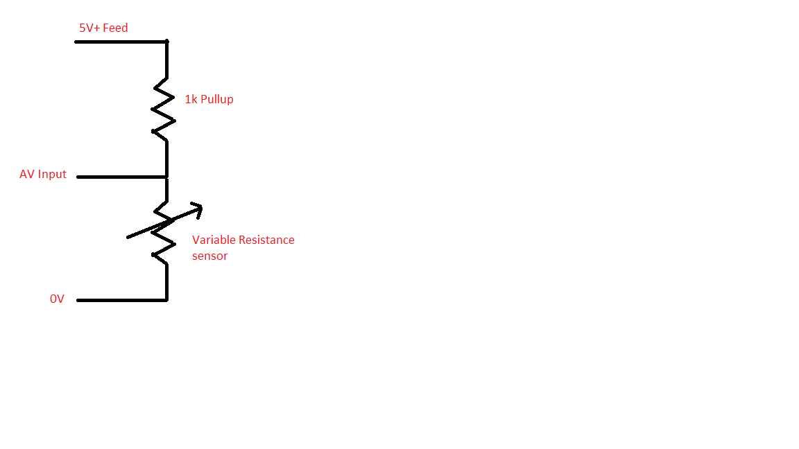
Where it has 1K, substitute 220 Ohm.
Thanks guys I’ll give that a go. The sender is 27 ohms full and 260 ohms empty.
off the subject, David I see your up to speed with motec PDM’s and Ecus. Noob question, would a single 8amp output from a pdm be sufficient to run all the battery pins on a m150 if it’s only just running basic setup. Just 8 injectors, ls coils. No iac valves etc.
Also, does D12 go to battery feed? Is it used?
thanks
The bat +ve pins of the M150 are used to power any internal components of the ECU and potentially power any components being high side controlled through the ECU such as servo motors.
Injectors and solenoids are low side controlled so the current is flowing though the ECU to the bat -ve pins.
D12 is not currently implemented so it does not need to be connected.
Hi Corrado,
The D12 Battery Backup is not used or needed.
You could run all of that from a single output, but I would recommend against it. My preference is to have the ECU powered off of one 8A output, and then the coils and injectors off of another. This allows for the ECU to be powered up without having the injectors and coils powered at the same time. This covers multiple situations, such as configuring the ECU requiring restarts and having the injectors/coils not powered means that they cannot be driven in an uncontrolled manner during the restart time. If you wire in an Ignition switch, you can use this to control the power supply to the injectors and coils, allowing for the engine to be stopped without power cycling the whole vehicle.
Depending on the injectors in use, you may need to run the injectors on a separate output to the coils.


