121 | Wideband Lambda Sensors - Essential knowledge
Summary
The wideband lambda sensor is one of the most critical aspects we need to monitor when performing any tuning. Not all widebands are created equal though and the sensor and controller you choose, as well as the way your sensor is installed can have a big impact on your sensor life as well as the accuracy of the readings. This webinar will cover the essential knowledge you should understand in order to get the best results.
| 00:00 | It's Andre from the High Performance Academy. |
| 00:02 | Welcome to this webinar. |
| 00:04 | In today's webinar we're going to be discussing some of the more intricate topics around wideband lambda or wideband oxygen sensors. |
| 00:15 | This is one of the sensors that we as professional tuners are relying on every time we've got an engine on the dyno or for that matter when we're doing any datalogging out on the road or racetrack. |
| 00:27 | This is the sensor that we are relying on to give us accurate and detailed information about the air fuel ratio that the engine is running at. |
| 00:38 | Since we're basing our fuel delivery tuning on the data it's essential that we can rely on it. |
| 00:47 | There's a few areas when it comes to the wideband sensor and wideband controller that we quite regularly get asked about. |
| 00:56 | Also a fair amount of misunderstanding and misconceptions about some of the aspects of wideband sensor selection, controller integration with your ECU or datalogger and also sensor location so this is the aim of today's webinar. |
| 01:14 | To give you some of the finer aspects of these wideband controller questions and also give you some of the benefit of what I've picked up over 15 years of experience in the industry. |
| 01:31 | One of the biggest problems and this is one of the things I've struck over my time in the industry is sensor life or in other words a short sensor life. |
| 01:40 | This is a really big problem, particularly if you are tuning for a profession. |
| 01:47 | These wideband sensors they have come down dramatically in price over the years. |
| 01:51 | However they still make up a reasonably considerable part of your consumable expense as a professional dyno tuner and understandably we want to minimize how many of these sensors we're burning through. |
| 02:06 | Even if you've got a sensor fitted in your car this can still be a problem. |
| 02:11 | A lot of customers, clients, or HPA members complain about short sensor life in their car and again this is an expense that we need to factor in so we'd really like to make sure that our sensors last a reasonable amount of time. |
| 02:27 | One of the things that is really easy to overlook here despite the fact that we are dealing with these products in the performance aftermarket is that these sensors are not designed and developed for us in a performance aftermarket application. |
| 02:42 | These same sensors are being used all around the world in OE applications and as such as you can imagine these sensors are expected and designed to at least outlast the OE manufacturer's warranty period. |
| 03:00 | That may be something like 100,000 kilometers or 100,000 miles. |
| 03:05 | If you aren't getting that sort of service life out of your wideband sensor then it can suggest that there are some problems. |
| 03:14 | While 100,000 kilometers in the aftermarket might not be particularly realistic, certainly if you're starting to burn through sensors every few weeks or every few months then there's quite likely to be some things that you can do that are going to extend that sensor life and get it out to something that's a little bit more realistic and a little bit easier on the pocket. |
| 03:40 | When it comes to wideband sensors and wideband controllers, one of the things to understand is that they aren't all created equal. |
| 03:50 | I'm going to talk about the wideband controller strategies and how that can affect sensor life a little bit further into the webinar but in particular before we do that let's just talk about the wideband sensors that we have as our common options out there in the aftermarket today. |
| 04:08 | The three that I'll talk about here, the three common ones that we see tend to be the Bosch LSU four point two, the Bosch LSU four point nine which has become probably arguably more popular over the last couple of years and also the NTK sensor and in the NTK sensor department there's also a variety or a range of different sensors that they produce. |
| 04:34 | I think that the Bosch LSU four point two and four point nine would easily be the more popular, the more common out there in the tuning world. |
| 04:44 | I'm not going to delve too deeply into the inner workings of how a wideband lambda sensor works. |
| 04:51 | It's simply not necessary to understand those inner workings in order to actually use the wideband sensor and then obviously tune the car. |
| 05:04 | However there is a lot of confusion about the different between LSU four point two and the LSU four point nine and I just wanted to briefly touch on that. |
| 05:14 | The LSU four point two which is an older sensor now, that uses a reference air cell to compare the exhaust gas reading to a stoichiometric air fuel ratio value. |
| 05:29 | What Bosch found is that in theory that all worked perfectly but out in the real world that reference air cell could become contaminated and this would affect the accuracy of the LSU four point two sensor's rating. |
| 05:46 | Particularly we saw some degradation in that sensor reading over time and a lot of the accuracy of that sensor and how far or how badly it degraded was to do with the installation and how likely it was to be contaminated or polluted. |
| 06:03 | The LSU four point nine which is Bosch's newer sensor on the other hand uses a reference pump current and this pump current is consistent or constant, it doesn't change. |
| 06:16 | Hence it's not prone to that contamination or pollution and the theory there is that the LSU four point nine will remain more accurate. |
| 06:28 | It's not prone to that same degradation of the LSU four point two. |
| 06:33 | There's a bit of confusion there about when the four point nine started becoming available to aftermarket and aftermarket wideband controllers there was a lot of talk about the improved accuracy of the readings and from my own research and my own testing that's simply not true. |
| 06:52 | In a good condition or good installation with two brand new sensors you should be seeing exactly comparable results between the four point two and the four point nine. |
| 07:02 | The four point nine should remain more consistent over time. |
| 07:07 | Also in terms of my own experience with the four point two versus the four point nine with the controllers that I have been using I have seen better life expectancy out of the LSU four point nine sensor. |
| 07:22 | However I can't specifically say if that is in relationship to the sensor itself or the wideband controller. |
| 07:31 | Again I'll talk more about the controllers a little bit further into today's webinar. |
| 07:37 | It's really important here to touch on another really big killer of these wideband sensors which is leaded fuels. |
| 07:47 | Particularly when I was running my old tuning workshop we were dealing with a lot of drag cars. |
| 07:55 | That was something we specialized in and in order to get really good performance out of these drag engines which were often running really high boost pressure we were typically using heavily leaded fuel. |
| 08:06 | The go to fuels that I was using were the VP Racing C16 and then a little bit later on a VP Racing Q16 sort of overtook C16 in the popularity stakes. |
| 08:21 | The LSU four point two sensors in particular were very very intolerant of those fuels and I have on a really bad day managed to destroy a brand new sensor straight out of the box in as little as one dyno session or actually to be more accurate within one dyno session I managed to kill the sensor before we'd actually managed to complete the tuning. |
| 08:47 | At the time just so you've got some sort of context around what I was using it was the Bosch LSU four point two sensor. |
| 08:56 | I think the actual part number was a six zero six six sensor so it had the longer rectangular plug on it. |
| 09:03 | Excuse me. |
| 09:05 | We were using a MoTeC PLM to control that sensor. |
| 09:11 | That got quite tiresome replacing the sensors so regularly and even with the non leaded fuels I found the life expectancy of the LSU four point two sensor was a little bit marginal. |
| 09:26 | We were probably on average replacing a sensor even on normal pump fuels perhaps in the region of every four to eight weeks. |
| 09:36 | That does again start to add up as a cost for your consumables. |
| 09:41 | We ended up making the change to the NTK sensor, the MoTeC PLM has the benefit of being able to be configured for either the LSU sensor or the NTK sensor and what we found was that the NTK sensor is a much more expensive sensor so top of my head I think we're paying around about three times the cost for the NTK sensor when compared to the LSU four point two. |
| 10:10 | However it seems to be a much more tolerant sensor of leaded fuels. |
| 10:15 | It seems to be much more tolerant and consistent in general and we went from replacing a sensor every four to six weeks to in some cases getting 12 months or more from a single sensor so understandably the extra expense of the NTK sensor well and truly made up for itself over the course of a year. |
| 10:37 | Just be aware that not all controllers can be configured for dual purpose of either the Bosch or NTK sensors so you do need to be careful there. |
| 10:49 | Now we're going to talk a little bit about the location of the sensor. |
| 10:54 | One of the things that I think is really often overlooked is the fact that any wideband sensor's reading is going to be dependent on the pressure that the sensor is being subjected to, so the tip of the sensor and the exhaust system. |
| 11:17 | Most people would completely disregard this and if you are running the sensor in the main exhaust post turbo charger if you're talking about a turbo charged engine we would like to think that that's a fairly safe assumption. |
| 11:32 | Where it really comes into its own is if we are fitting the sensors pre turbocharger. |
| 11:39 | In that case there is going to be much more pressure being subjected to the sensor so it's not uncommon for example to see as much as twice boost pressure in the exhaust manifold. |
| 11:52 | What I mean by this is if we were running 15 PSI of boost pressure in your inlet manifold it wouldn't be uncommon to see perhaps 30 PSI of back pressure in the exhaust manifold and this will have a significant effect on the accuracy of your reading. |
| 12:10 | At something like 30 PSI of gauge pressure acting on the sensor we're going to see the reading drop much richer than actual so it's really being influenced quite dramatically by that pressure. |
| 12:24 | I think a lot of tuners at this point really do understand that pre turbocharger pressure will affect our accuracy but the thing that is really easy to overlook is that if we are fitting the sensor to the exhaust system, particularly if it is up near the collector of a naturally aspirated engine or it's fitted just off the turbocharger outlet then we are at this point before the catalytic converter, before any mufflers and we may have a relatively restrictive factory exhaust system and in those situations it's not uncommon to see quite a significant back pressure reading, particularly at high RPM. |
| 13:04 | It may be quite easy to see four, five or even eight PSI or more of back pressure and this does get to a point where it is starting to make a noticeable impact on our air fuel ratio reading. |
| 13:20 | The dangerous part here is that the sensor reading will actually be richer than actual so if you're taking that data and using it as gospel the tendency would be to start leaning out the air fuel ratio to get back to your target and the actual air fuel ratio the engine is running at will be leaner than what the sensor is reporting. |
| 13:43 | It's really important to understand that and take that on board, particularly if you are running a very restrictive exhaust system that could be creating a lot of pressure. |
| 13:53 | The other aspect here to consider in relation to our sensor life is the temperature tolerance of the sensor. |
| 14:03 | Most of these sensors are rated to no more than about 930 degrees Centigrade exhaust gas temperature for continuous operation. |
| 14:14 | The LSU four point two and LSU four point nine both will support 1030 degrees Centigrade for intermittent use but obviously at the higher temperatures we start to see the sensor life begin to suffer. |
| 14:31 | If we're fitting the sensors to a naturally aspirated engine or we're fitting them post turbocharger on a turbocharged engine then the exhaust gas temperature should not present an issue to the sensor itself. |
| 14:46 | It should be well underneath those sort of levels. |
| 14:48 | However two areas that do need to be considered there for sensor temperature would be if we are using a pre-turbo configuration we're likely to see much higher exhaust gas temperatures pre-turbo than post-turbo, and the other application which is really well known for eating through sensors at a relatively high rate is in a rotary, particularly rotary turbochargers. |
| 15:11 | Much, much higher exhaust gas temperatures than a piston engine. |
| 15:18 | Now I want to move on and talk about the accuracy of the wideband controller and this is a really big problem for us. |
| 15:27 | In the past at times I've had the opportunity to test back to back two or three different wideband controllers, all fitted to the same exhaust system within a space of about 12 inches of the exhaust system. |
| 15:43 | Essentially under those test conditions while I do admit it's not laboratory grade testing I would be reasonably confident in saying that the air fuel ratio that all of those sensors were measuring should be very very close to identical. |
| 16:01 | However what we tend to see is that if we test three different wideband controllers we're likely to see three different readings. |
| 16:10 | Sometimes this could be quite minor. |
| 16:13 | We might see that the reading could be within perhaps one or two percent and other times which is a little bit concerning we see a much wider spread of perhaps, five or even 10 percent in our air fuel ratio readings. |
| 16:26 | This is probably one of the harder questions to answer. |
| 16:30 | I've seen this commented in our forums as well. |
| 16:34 | How do you know what to believe? The answer there is often we don't. |
| 16:40 | When we see a digital number being presented on our laptop screen or on our dyno screen it's always something that we want to believe and just because it's a digital number there being presented doesn't necessarily mean it is going to be accuracy or it is going to be correct. |
| 17:02 | One of the really good ways to check the accuracy of our wideband reading is particularly if we've got the sensor fitted to a factory car, hopefully a late model factory car that we know is relatively unmodified and in good working order what we should find is that due to the closed loop fuel control of the factory car at idle and cruise, we know that the air fuel ratio should be very close to stoic so we should be seeing lambda one or 14 point seven to one on pump gas. |
| 17:41 | Very very close to that so if our wideband reading from our auxiliary wideband controller is varying from that range then that would be a really good reason to be suspicious. |
| 17:52 | If we're out at lambda one or stoic then it's likely we're also going to be out at the richer mixtures we're going to be wanting to target at wide open throttle. |
| 18:04 | Personally what I've always done through my tuning career is I started with a Dynapack dyno that had built in MoTeC PLMs and then we've moved on now to our mainline dyno which we've also retrofitted MoTeC PLMs into. |
| 18:21 | This is where it gets a little difficult. |
| 18:25 | I can't sit here and tell you that the MoTeC PLM is 100% accurate and I'm going to talk a little bit more about the accuracy of these controllers and their calibrations shortly but what I can tell you is that over 15 years of tuning a huge range of different engines, anything from very very low powered naturally aspirated engines to extremely high boost turbocharged engines I developed a sort of range of air fuel ratio lambda numbers based on the PLM reading that I knew were safe and I've developed all of my tuning knowledge around that. |
| 19:00 | What I tend to find is that I guess you could say I've calibrated my own tuning targets in terms of air fuel ratio lambda numbers to what the PLM outputs and I'm comfortable with that. |
| 19:13 | Understandably now what I look to is I tend to reference everything back to the PLM readings so for example when I'm choosing a portable wideband which I'll use out on the road or if I'm looking at the calibration of a built in wideband on a standalone ECU, I'm going to be looking at how closely that matches what the PLMs fitted to my dyno are reading and what I'm hoping is that they're going to be reasonably close. |
| 19:44 | For my road tuning duties I typically rely on an Innovate LM-2 and I've found that the Innovate LM-2 reads within a couple of percent of the MoTeC PLM, hence the numbers I see are comparable and I know that I'm comparing apples with apples and I'm safe turning to the same lambda targets. |
| 20:03 | If you've got something that's dramatically reading away from that then this is where you need to start either developing your own knowledge around that controller or perhaps looking at different controllers. |
| 20:17 | When it comes to the actual wideband sensor or wideband controller, one of the really critical aspects is the actual calibration. |
| 20:26 | It doesn't really matter what wideband controller you're using if the calibration is not correct for the sensor then you can't hope to get a reading that is going to be useful. |
| 20:37 | There's two typical ways that the calibration is performed. |
| 20:42 | In the aftermarket it has been most common to use what's known as a free air calibration and that's where as its name implies we take the sensor out of the exhaust system, we expose it to free air. |
| 20:57 | We need to make sure that that free air is in fact clean air. |
| 21:01 | We don't want to be doing this in a workshop where we've had cars running and exhaust gas has contaminated that air. |
| 21:08 | What we're doing is then taking a reading of the O2 concentration in that free air and that essentially calibrates the sensor. |
| 21:17 | That's pretty common. |
| 21:18 | The other way that is now becoming quite common with a lot of the lambda controllers or wideband controllers is to actually use the built in calibration resistor that's fitted to these wideband sensors. |
| 21:35 | When the wideband sensor is produced by the likes of Bosch it has a calibration sensor and if the wideband controller can read that calibration sensor, the calibration sensor by the way is fitted to the connector of the lambda sensor. |
| 21:50 | If the connector of the wideband controller can directly read that calibration sensor then it can automatically calibration its output to suit that sensor. |
| 22:00 | An interesting side aspect of this as well, we attended PRI a couple of years ago and listened to a seminar presented by Bosch, a couple of the Bosch engineers about these calibration sensors and one thing that I didn't realize is that that calibration sensor actually calibrates the lambda sensor output at two separate points whereas if we're doing a free air calibration we are only calibrating at one point, hence technically and according to Bosch if we're using and reading that calibration sensor we should technically get a more accurate calibration and a more accurate reading as well, so that's something to take into account. |
| 22:45 | For anyone who's followed our courses or followed our webinars in detail, you've probably already heard me talk about the problems that can creep in from outputting the lambda data or air fuel ratio data from a standalone wideband controller into an ECU, into a dyno or into a data logger. |
| 23:08 | This is one oft he most dangerous areas where we're going to blindly take that information and believe it. |
| 23:16 | There's three main ways that that data can be transported or transmitted from the wideband controller into our ECU dyno or data logger. |
| 23:25 | These include an analog voltage where the wideband controller is simply outputting perhaps a zero to five volt output that varies in relation to the current wideband reading, the air fuel ratio reading. |
| 23:38 | It can transmit this data via CAN and that's going to be great for any ECUs or components that are able to read information over a CAN network. |
| 23:49 | Also we see some products the likes of the wideband controllers coming from Innovate for example where the data can be transmitted over a serial communication protocol. |
| 24:03 | I'll touch for a start on analog because it is my least favorite. |
| 24:07 | It is the most problematic and it is also probably the most popular and most common. |
| 24:14 | When we've got an analog voltage output like this as I say we may be looking at a zero to five volt output. |
| 24:20 | It may be even zero to one or two point five. |
| 24:23 | It depends on the calibration in the wideband controller. |
| 24:27 | What we are relying on there is that the voltage reaching our ECU or data logging device absolutely accurately matches what the wideband controller is putting out. |
| 24:38 | Otherwise, our wideband reading will be skewed. |
| 24:42 | You might be thinking well why wouldn't that voltage match what the wideband controller is putting out? Its very very easy to have ground offsets creep in and it doesn't take much more than a tenth of a volt of an offset to have a dramatic impact on the accuracy of our reading. |
| 25:01 | I found these are notoriously difficult to set up and calibration properly and really you do need to be very very careful. |
| 25:09 | First of all following the manufacturer's instructions to the T to make sure that you've installed that product and grounded it correctly. |
| 25:19 | One of the keys here is making sure that you've run your sensor ground from your wideband controller to a sensor ground input on your ECU or data logger. |
| 25:28 | This should hopefully remove most of the problems with these ground offsets. |
| 25:35 | Another problem though with analog voltage outputs is it's very difficult if not impossible to include any diagnostics data across that communication stream. |
| 25:47 | What this means is that if the sensor is still cold and it's being heated up we're not going to get a good reading. |
| 25:56 | Generally what will happen is that these analog outputs will either go to a fixed value or perhaps a high voltage or low voltage state so the ECU isn't getting accurate data at that time while the sensor's heating up. |
| 26:09 | This makes it impossible for the ECU to know what's going on and it'll affect the ability for the ECU to perform good closed loop control on the sensor while it is still heating up. |
| 26:21 | Likewise if there is a diagnostic problem with the sensor the ECU doesn't know this and we're quite likely, particularly if the sensor fails to end up with a very lean or very rich reading and again this affects the ability of the ECU to perform proper closed loop control, if that's what you're using the sensor for. |
| 26:41 | With both CAN and serial communication on the other hand we have guaranteed integrity of that data. |
| 26:49 | The way the data is being transmitted over those two protocols means that we can be confident that the number that we're seeing on the laptop or the dyno screen for example is exactly what the wideband controller was intending to send out. |
| 27:04 | Remember that this doesn't necessarily mean that it's going to match another product but at least we're ahead of the curve here because the reading is what the manufacturer at least intended to be sending out. |
| 27:16 | Again this comes back to where we can check under closed loop conditions and make sure that we are seeing a stoichiometric air fuel ratio reading. |
| 27:24 | The other real advantage with CAN and serial communications though is we do get the benefit of the ability to have diagnostic data included. |
| 27:35 | Really here this relies on both the product, the wideband controller actually sending diagnostic information as well as the ECU or whatever product you're reading it from being able to decode and use that diagnostic data for something meaningful. |
| 27:52 | Essentially what we want here for a closed loop control strategy for example in an ECU we want the ECU to ignore the wideband input until the sensor is up to temperature and reading correctly. |
| 28:03 | Then it can go into closed loop control mode. |
| 28:06 | If at any time the sensor goes into fault again the closed loop control should be disabled and that's the benefit of that diagnostic. |
| 28:18 | Now we're going to move into some questsions and answers in a few minutes so if you do have anything that you would like to ask, anything that you'd like me to touch on please ask those now in the chat and Colin or Ben will transfer those through to me. |
| 28:33 | We'll move on to talking about some of the common reasons for sensor failure that we are seeing in the aftermarket and what we can do to minimize these failures. |
| 28:43 | One of the most common I find is moisture. |
| 28:47 | What you need to understand is that the way the wideband sensor works is that it has a ceramic element, sensing element in it that's heated up to a very high temperature. |
| 29:00 | Understandably if we introduce moisture to this glowing red ceramic, it's very very easy for that ceramic to be damaged or fractured and this can very quickly destroy a sensor. |
| 29:12 | We need to be very careful with the moisture that's being introduced to the sensor. |
| 29:18 | I'm going to talk about how we can minimize that shortly. |
| 29:22 | Moving on the next thing that's important to understand is that the sensor can be damaged by shock or vibration. |
| 29:30 | Again this is something that we can end up introducing in a modified car that might not be present in a factory car. |
| 29:39 | Anything that's going to introduce harmonics or vibration into the exhaust system that could potentially end up damaging our sensor and we need to be careful with that. |
| 29:49 | Of course it should go without saying that if we drop the sensor this can also quickly destroy it. |
| 29:57 | Leaded fuels which I've touched on we obviously want to minimize the influence of leaded fuels. |
| 30:04 | I'll just touch on this as well because this is another question we quite often get. |
| 30:07 | In my own experience E85 and methanol fuels which I've done a lot of tuning on tend to offer really really good sensor life. |
| 30:19 | They don't tend to affect the sensor at all. |
| 30:23 | Generally I can tune on those fuels with relative immunity from sensor failure. |
| 30:28 | Certainly it's no worse than tuning on a normal unleaded pump fuel. |
| 30:34 | Along with our shock and vibration another aspect that can easily damage the sensor is thermal shock. |
| 30:41 | This can be sort of hand in hand with moisture. |
| 30:44 | If we end up introducing a lot of moisture into the exhaust when the sensor is hot the thermal shock can also damage the sensor there. |
| 30:53 | This really comes down as well to one of the more common issues that we're hearing reported in the aftermarket is the controller circuit that actually controls the heater operation in the sensor. |
| 31:07 | This is really where it comes down to not all wideband controllers are made equal and some do have the tendency to damage the sensors relatively quickly. |
| 31:19 | One of the examples I'll give here is the Innovate LC-1. |
| 31:24 | This is a wideband controller I used quite extensively many many years ago, probably more than eight years ago now was when I was using those. |
| 31:34 | While I obviously don't understand or don't know exactly how Innovate were driving the lambda sensor or the heater circuit and the lambda sensor I'm lead to believe that they used a very aggressive strategy there. |
| 31:50 | They drove the heater very very hard using a lot of current and this is reported to have lead to a lot of the failures. |
| 31:59 | On the later equipment, particularly the LC-2 which sort of superseded the LC-1, I've seen very very good service life from that particular controller. |
| 32:11 | That actually uses their own digital control strategy as well. |
| 32:16 | Just understand there that not all wideband controllers are created equal. |
| 32:25 | Location in the exhaust system as well is another really key aspect to understand here. |
| 32:32 | In terms of the moisture content of the exhaust gases a good way of improving sensor life is to mount the sensor above horizontal. |
| 32:44 | What I mean by this is if we have the sensor mounted sort of down around the lower extremities of the exhaust system then this is where we're likely to have moisture collecting, particularly during a cold start. |
| 32:56 | This can damage the sensors so generally I like to try to have that sensor mounted above horizontal, particularly in late model engine bays we can be very limited on exactly where we can fit the sensor. |
| 33:11 | Sometimes we have an optimal solution where we would like to fit the sensor and just due to packaging reasons we can't actually fit the sensor where we'd like to. |
| 33:22 | That's another consideration that you do need to keep in mind, where the sensor is located will potentially affect the sensor life. |
| 33:35 | In terms of the sensor location as well it's also important to understand that the wideband sensor is actually just giving us an average air fuel ratio reading. |
| 33:45 | What I mean by this is that if we have a four cylinder engine and we've got the wideband sensor fitted in the collector of the exhaust manifold it's actually giving us the average of the air fuel ratio on all four cylinders so it's quite possible for example to have two cylinders running at stoic, one cylinder running very slightly richer than stoic, and one cylinder running very slightly leaner than stoic and the overall reading coming out of our wideband sensor still would be stoic or lambda one, so just giving us the average of all of our cylinders. |
| 34:24 | This plays into the importance of our sensor location understandably if we are going to be restricted to using just a single sensor we'd ideally like to be monitoring all of the cylinders on that engine. |
| 34:37 | If we do have a four cylinder engine we'd like to have that fitted in the collector. |
| 34:42 | We wouldn't want to be fitting the sensor just to a single exhaust runner. |
| 34:47 | That's likely to give us potentially inaccurate data. |
| 34:50 | Likewise if we're talking about a V configuration engine, either a V-6 or a V-8, if we are going to run a single sensor as long as the exhaust does merge at one point it would be sensible to have that sensor fitted where the exhaust system merges. |
| 35:07 | In the ideal world, ideally what we would have is a different sensor, one sensor for each bank and that would be able to allow us to measure any bank to bank air fuel ratio variations. |
| 35:22 | Another really common question here is should we be mounting the sensor pre or post catalytic converter and what difference do we see with the readings before and after a catalytic converter. |
| 35:40 | Personally in all of my tuning I've always been of the opinion that to get the best results we probably want to mount the sensor where the OE do which is pre catalytic converter. |
| 35:52 | There's a couple of reasons why I like to do this. |
| 35:55 | First of all we're going to be mounting the sensor typically here quite close to the engine itself so this is going to result in a reduction in the latency between an air fuel ratio change and the sensor reporting that. |
| 36:11 | If we've got the sensor fitted right at the end of the tailpipe particularly at low RPM there tends to be a little bit of lag or latency in our reading as the exhaust gases actually make their way through the system from the exhaust ports all the way to the sensor. |
| 36:26 | Secondly when we've got the sensor fitted right at the front of the engine pre catalytic converter, obviously as long as our exhaust system is well sealed, we don't have any exhaust leaks, we're not going to have our sensor affected by ambient oxygen which is so often the case with a wideband sensor fitted in a tailpipe. |
| 36:48 | This means that particularly at very light throttle cruise, idle, et cetera we're getting much more accurate readings than what we could with a tailpipe kit mounted oxygen sensor. |
| 37:02 | In terms of the reading difference pre and post catalytic converter I have done my own testing on this and I've honestly never seen anything that I would count as significant. |
| 37:14 | The way the catalytic converter does work it does alter or adjust the components, the composition of the exhaust gas stream and technically yes this should or can affect our lambda reading. |
| 37:29 | Personally I've never seen anything dramatic enough to actually affect our lambda reading or our tuning. |
| 37:38 | The other thing to consider here goes back to what I was talking about earlier with the back pressure that can affect our sensor as well. |
| 37:48 | When we're pre catalytic converter particularly when we're talking about a factory exhaust system it's likely in this installation that we will have a reasonable amount of back pressure so this can be influencing our sensor reading in itself. |
| 38:04 | Really unless we've got a pressure sensor and we are compensating for that which is very very unlikely if not very rare in my own experience, there's likely to be some small discrepancies creep in as a result of that as well. |
| 38:21 | Really the key is understanding how all of these can affect our tuning and really when we're considering back pressure the difference pre and post catalytic converter is probably not significant enough for us to worry about. |
| 38:38 | The other aspect is a lot of tuners will rely on a tailpipe kit fitted into the rear muffler of the car. |
| 38:46 | I'll just jump across. |
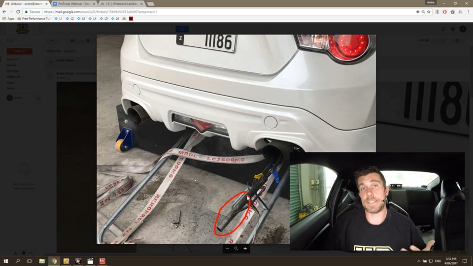
| 38:48 | If we can go to my laptop screen for a moment, I'll just start the car while I'm talking. |
| 38:53 | This is actually what I've got sitting in the back of our Toyota 86 at the moment. |
| 38:58 | We've got the mainline exhaust gas tailpipe kit fitted into the rear muffler. |
| 39:05 | This is actually quite a reasonable installation because in particular, if we can see it here it's probably not very clear, the probe that comes off this kit is actually quite long. |
| 39:17 | It's probably just about as much installed into the exhaust system right now as what you can visibly see and we've got the NTK lambda sensor fitted into this as well. |
| 39:30 | The problem with these sorts of installations is particularly when we've got low exhaust flow such as what we've got right now at idle, we can have the sensor influenced by ambient oxygen. |
| 39:45 | In some instances we may be getting ambient oxygen entering the exhaust tailpipe and then entering the measurement tube. |
| 39:53 | In this case we've also only got a relatively short distance from the sensor to open air so we can end up with ambient oxygen making its way back up and reaching the sensor and affecting our reading. |
| 40:09 | Just to show you how that can affect everything let's have a quick look. |
| 40:16 | If we jump across to our dyno screen I'll just show you a comparison of the lambda reading here on our dyno screen. |
| 40:23 | The one were looking at here is lambda LTC zero one. |
| 40:27 | You can see that's sitting at the moment at 22 point six, so this is the maximum lean reading. |
| 40:33 | What I'll do now is if we can just have a look at my laptop screen at the same time, hopefully Colin's got that set up, we can see right here in yellow in the middle we have our exhaust lambda reading which is sitting at lambda one which is also our fuel mixture aim. |
| 40:48 | The point of all of this is at idle right now with that tailpipe probe our lambda reading is completely irrelevant. |
| 40:57 | We can't take any notice of it. |
| 40:59 | It's absolutely useless and hence this would make it impossible for us to correctly tune our idle. |
| 41:06 | What I'll do now is we'll just get our engine running on the dyno. |
| 41:10 | I'll just bring the RPM up so you can see how the increased exhaust gas flow as we bring the RPM and the engine load up affects everything. |
| 41:22 | I'll just go into fourth gear here. |
| 41:27 | We'll come down to about 2000 RPM, just allow the dyno to stabilize and you can see right now we've achieved our lambda target, lambda one. |
| 41:40 | If we look at the dyno though we can see that we're still sitting at around four to five percent, or it is moving around, two to five percent leaner than lambda one. |
| 41:50 | We've still got an influence there. |
| 41:52 | We still haven't got an accurate reading. |
| 41:54 | At the moment I'm at 2000 RPM and I'm at 20% throttle, so a very light throttle. |
| 42:00 | Again this would affect the accuracy or our ability to achieve accurate air fuel ratio targets at light throttle cruise. |
| 42:08 | What I'll do now is we'll just bring our engine RPM up a little bit. |
| 42:11 | We'll come up to two and a half thousand RPM and I'll just put a little bit more throttle on board. |
| 42:18 | What this is doing as I increase the throttle opening is it's also affecting our exhaust gas flow. |
| 42:24 | We've got more exhaust gas moving through the exhaust system. |
| 42:27 | Right now we can see 26 hundred RPM, 40% throttle. |
| 42:31 | We're sitting on our lambda target of zero point nine four and if we look at our dyno at this point we're essentially right on our target. |
| 42:40 | Obviously it's still moving around a little bit but at this point we're within about one percent. |
| 42:45 | The important thing to understand is if you are going to use a tailpipe kit for your tuning on a dyno you do need to understand the implications or the effect that's going to have on the accuracy of those readings particularly when you have very very low exhaust flow. |
| 43:05 | That's not necessarily going to say that we shouldn't be using a tailpipe kit but it's a case of choosing when and where you're going to use that and what applications it's going to be suitable for. |
| 43:17 | For me personally if I'm tuning a standalone aftermarket ECU where I need to be able to accurately tune every aspect of the fuel delivery, idle, light throttle cruise through to full power, I'm going to be fitting the wideband sensor into a weld boss in the exhaust. |
| 43:34 | As I've mentioned generally near the front of the exhaust system. |
| 43:39 | However where I would use a tailpipe extension kit like this because it is much quicker and easier to fit to the car would be perhaps if I was refleshing a stock ECU where I knew that I wasn't going to be doing anything much in the way of idle or cruise tuning. |
| 43:55 | A really good example of this would be a standard or very very lightly modified vehicle where we will often be concentrating all of our refleshing efforts solely on the wide open throttle operation. |
| 44:08 | On the wide open throttle where we have that higher exhaust gas flow we can be reasonably confident that our sensor reading will be accurate and the other thing is if we are wanting to look at our light throttle cruise or idle tuning then we have the benefit of the short term and long term fuel trims on the factory ECU to guide us as to whether or not our calibration for let's say our speed density or mass airflow, is sensor accurate. |
| 44:39 | If our trims are way out then obviously this may indicate that we've got a little bit of work to do. |
| 44:45 | Lastly I glanced over this so I'm just going to come back to it. |
| 44:48 | I said I would talk about the calibration as well. |
| 44:51 | This comes from a conversation I had with one of the hardware engineers or software engineers I should say that works for Link Engine Management here in New Zealand, when they developed their CAN lambda unit. |
| 45:04 | That's a standalone wideband unit that transmits lambda or wideband air fuel ratio data via CAN. |
| 45:12 | They bought all of their required hardware and control circuitry from Bosch and as part of that they end up with all of the relevant documentation from Bosch as to how to set up that sensor and how to correctly calibrate it. |
| 45:29 | Obviously in a laboratory setting you can calibrate the sensor reading with a control gas sample and on the basis of it or at least how I expected it to work that would be cut and dry. |
| 45:43 | We calibrate the sensor, make sure our circuitry's working, calibrate the sensor using a control gas sample and lambda one is lambda one, lambda point eight is point eight and we're done, put it on the car and it's finished. |
| 45:58 | Unfortunately as it would appear it's not quite that simple and Bosch actually advised that the final calibration must be done to suit the specific application on the engine or the application the sensor's being used for. |
| 46:12 | What Link found is if the sensor was calibrated using a control gas sample as you would expect in a laboratory, in the real world the sensor reading was dramatically different from just about anything else they tested. |
| 46:28 | What i mean by that is other manufacturers' products. |
| 46:31 | At this point Link were actually in a situation which every manufacturer has obviously also faced where they needed to adjust their calibration to suit what we as tuners as acceptable so everything actually lined up with numbers that we expected. |
| 46:48 | This is why we can see quite a large variation in air fuel ratio readings from different manufacturers' products, because a lot of it comes down to how that manufacturer has decided in the final run to actually adjust their calibration or what they actually wanted to see from the calibration or the sensor. |
| 47:12 | I'll move into questions really shortly. |
| 47:15 | There is one more aspect that I wanted to touch on here and that is the reading between air fuel ratio and lambda. |
| 47:25 | This probably goes a little bit further than just talking about wideband sensors, but again this is an area there's a huge amount of confusion or misunderstanding and I just wanted to touch on this. |
| 47:36 | If you want to jump in in more detail this is dealt with in a lot more detail in our understanding air fuel ratio course. |
| 47:44 | A lot of tuners, particularly I find in the US market, prefer to tune in units of air fuel ratio. |
| 47:53 | Personally I prefer units of lambda because it's much easier, particularly when we're using a lot of different fuels with different stoichiometric air fuel ratios. |
| 48:03 | Lambda one is always lambda one. |
| 48:06 | It's always stoichiometric regardless of the fuel. |
| 48:10 | This is where a little bit of the confusion creeps in. |
| 48:13 | People easily overlook the fact that natively a wideband sensor actually reads in units of lambda. |
| 48:22 | What it's doing is it's looking at the exhaust gas and it's telling us whether we have an excess of oxygen or an excess of hydrocarbons in the exhaust system. |
| 48:31 | Basically what it's doing is it's delivering us a reading relative to stoichiometric. |
| 48:37 | Remember the sensor doesn't know or care what fuel the engine's running on. |
| 48:41 | All it knows is the composition of the exhaust gas going past it. |
| 48:46 | Natively that wideband sensor is reading in units of lambda. |
| 48:51 | If we want to display our wideband information in units of air fuel ratio then the wideband controller needs to perform a calculation to do so. |
| 49:03 | This is why you'll find that your wideband sensor, your wideband controller or your ECU will have a stoichiometric air fuel ratio setting. |
| 49:13 | Because pump fuel is by far and away still the most common and popular fuel to be tuning it's natural that that default value our stoichiometric air fuel ratio setting is 14 point seven to one. |
| 49:26 | How the wideband controller works is let's say it's reading lambda one. |
| 49:30 | It wants to convert into units of air fuel ratio. |
| 49:33 | It multiplies lambda one by 14 point seven, the stoichiometric air fuel ratio setting and then obviously the output is in units of air fuel ratio. |
| 49:43 | It equals 14 point seven. |
| 49:45 | If we start to veer away from stoichiometric though, let's have a look at perhaps a lambda value of zero point eight five. |
| 49:53 | On the lambda scale, smaller numbers are richer than stoic so zero point eight five, again we multiply that by 14 point seven, our stoichiometric air fuel ratio setting. |
| 50:03 | That gives us an air fuel ratio value of 12 point five to one. |
| 50:07 | Now we're tuning on pump fuel, happy days, everything works nicely. |
| 50:12 | The confusion comes in when we start jumping from one fuel to another and this is an area of constant confusion as when tuners to from pump fuel to E85. |
| 50:23 | When we go from pump fuel to E85 our stoichiometric air fuel ratio changes from 14 point seven on pump fuel to nine point eight to one for E85. |
| 50:33 | Technically if we want to be absolutely correct what we would end up doing is adjusting the stoichiometric air fuel ratio setting on our wideband controller from 14 point seven to one through to nine point eight to one and this will give us accurate numbers on E85. |
| 50:54 | If we take for example our example of zero point eight five lambda, so we know that on pump fuel 14 point seven to one stoic, that equaled 12 point five to one. |
| 51:08 | If we've adjusted our stoichiometric air fuel ratio setting on our wideband controller as we've gone from pump fuel to E85 we would have entered a new value of nine point eight to one. |
| 51:19 | Our same lambda value, zero point eight five, multiplying this now by nine point eight to one gives us a air fuel ratio reading on E85 of eight point three to one. |
| 51:31 | Very dramatically different, but what you'll find is that by far the majority of tuners out there don't really understand this. |
| 51:39 | They never adjust the stoichiometric air fuel ratio setting on their wideband controller and hence they are still using target air fuel ratio numbers for pump fuel even when they're tuning on E85. |
| 51:53 | This is why you'll hear a lot of tuners still targeting values such as maybe 11 point five to one or 12 to one even when they're tuning on E85. |
| 52:02 | The confusion comes in because they simply don't understand the implications of that change. |
| 52:11 | Right, so we'll move into some questions now. |
| 52:14 | Again if you do have any more please ask them in the chat and I'll get onto them shortly. |
| 52:19 | Our first question comes from Motorsport Electronics. |
| 52:23 | He's asked what's the best way to determine the time offset for a lambda sensor when using closed loop lambda control. |
| 52:29 | Set a fuel cut at various RPMs and measure the time. |
| 52:32 | Really good question there and particularly on a lot on the ECUs that we tune we have an update rate for the lambda sensor. |
| 52:41 | This sort of comes back to something that I touched on earlier which is there is a latency or a lag between the exhaust gas exiting the cylinders and actually making it to the sensor and that latency or lag is going to depend to a degree on the exhaust mass flow. |
| 53:00 | What we see is a greater latency or lag at idle than what we're likely to see at very high RPM. |
| 53:08 | A lot of it comes down to what we're using that closed loop control strategy in the first place. |
| 53:13 | What we could do there is request a lambda change. |
| 53:17 | That would be a really easy way to do it, or alternatively produce a definite step in our fuel table. |
| 53:26 | For example, highlight the entire area that the engine is currently in and ask for a 10% change in air fuel ratio and change in fueling, and as soon as we press enter that change is locked in, so then what we can do looking at our data is see how long between making that change and the actual lambda value being monitored changing. |
| 53:49 | That's a really easy way of doing it. |
| 53:52 | The practical side of this is it's probably not super critical or not as critical as we think. |
| 54:00 | What we really want to do here is adjust the update rate or the rate of how often the ECU is looking at that lambda sensor until we're getting good control and that's really what I'm basing my decisions on. |
| 54:14 | For example at idle where our latency or lag is quite high, we're going to be using a slow update rate, perhaps two or maybe three times a second. |
| 54:24 | If we've got that update rate too fast what we're going to find is that our air fuel ratio is going to start oscillating. |
| 54:31 | It's going to move up and down around our target because there'll be a slight lean reading. |
| 54:37 | What happens is the ECU is adds fuel. |
| 54:41 | It doesn't instantly see a change from that extra fuel, so it's looking at the sensor again. |
| 54:46 | It's still lean, it adds more fuel, looks at the sensor, it's still lean, it adds more fuel. |
| 54:50 | Then all of a sudden the actual changes in air fuel ratio start making their way down the exhaust system. |
| 54:56 | The sensor starts reading rich, so conversely the sensor's now reading rich, the ECU is removing fuel, it has no effect, removes fuel, so we just constantly end up with this oscillation. |
| 55:07 | Really the practical sense of tuning this is adjusting the update rate until we are not seeing that oscillation. |
| 55:15 | I like to compare it a little bit to PID tuning. |
| 55:17 | What I'm going to do is start with a very low update rate and I'm going to constantly double that update rate until the system becomes unstable and starts oscillating. |
| 55:27 | Then I know the sort of range of values I'm working in. |
| 55:30 | I can start halving those values and get back down into a sort of a value where I'm getting good control without oscillation. |
| 55:37 | Hopefully that answers your question there. |
| 55:40 | Emfiz says if I'm tuning based on the factory wideband but the car has an angled O2 bung in the downpipe to avoid check engine lights, is it viable to use a separate O2 sensor and compare lambda values to compensate or is this too unreliable? Okay so what I'm taking from this is you're using a sensor fitting that's reducing the flow to the lambda sensor to avoid a check engine light. |
| 56:09 | This still shouldn't affect the accuracy of the reading. |
| 56:13 | It may affect possibly a latency. |
| 56:16 | It's not something I've often tuned with myself so I can't really give you too much information on that. |
| 56:24 | I would always be basing my own tuning however on an auxiliary wideband that I know and trust and the reason for this is that while a lot of the late model cars are starting to come out with wideband sensors, typically in the past almost all cars were fitted with narrow band sensors which are only useful around stoichiometric air fuel ratios, a lot of these cars now are coming out with wideband sensors. |
| 56:51 | However they're still predominantly being used for control at stoic for emissions purposes and often we'll find that while they are a wideband sensor and they will give a reading even perhaps as rich as 12 and a half, maybe 12 to one, what we find is compared to an accurate aftermarket wideband sensor as we move further away from stoic their accuracy diminishes so that's something you need to watch. |
| 57:16 | I can't say that that is accurate for all cars. |
| 57:19 | A good example recently we had a Porsche nine nine six, twin turbo on the dyno. |
| 57:25 | These factory ECUs from Porsche or Bosch are run constantly in closed loop mode even under wide open throttle with wideband sensors and they absolutely accurately matched what I was reading with our dyno as well. |
| 57:39 | It's really a case of every car can be different. |
| 57:46 | TDEChamp asks what's the best way to deal with suspected or known back pressure in NA cars affecting readings? Look I mean you can compare a reading here with a sensor fitted up near the collector and perhaps then do another run with a sensor fitted in a tailpipe kit and that is something that I have done in the past with an exhaust system that had excessive back pressure. |
| 58:11 | That actually was on a turbocharged car and the problems were making themselves present in a number of other ways that weren't my lambda reading. |
| 58:21 | On a naturally aspirated car though I would say it would be relatively uncommon although not impossible to have enough back pressure to really throw out your lambda readings significantly. |
| 58:35 | One other thing I'll just touch on this as well because I've done some testing with a preturbo wideband installation using both a Bosch four point two and a Bosch four point nine lambda sensor and from my testing it seems that the four point two sensor was more sensitive to back pressure than the four point nine, so even there can be a change there based on the sensor you're using. |
| 59:04 | Alright that brings us to the end of the questions and hopefully that's given you some more insight and understanding into the world of wideband sensors and wideband controllers. |
| 59:13 | Hopefully that will help you with your tuning. |
| 59:16 | As usual if you do have any more questions that crop up after this webinar has aired, please ask those in the forum and I would be happy to answer them there. |
| 59:26 | Thank you for joining us and I look forward to seeing everyone next week. |


