163 | TPS + MAP Tuning for Turbo and ITB - Alpha N
Summary
When faced with tuning a turbocharged engine with individual throttle bodies, the MAP signal on it’s own is no longer a good indication of engine load. For this reason we need to use a more advanced tuning technique where the main fuel table is scheduled relative to TPS and we use an overlay table based on MAP to correct the air fuel ratio as the manifold pressure changes. In this webinar we’ll investigate a range of techniques to achieve this result using an R32 GTR fitted with a Link G4+ ECU.
| 00:00 | - In this webinar we're going to be investigating the situation where we've got an engine with individual throttle bodies and a turbo charger. |
| 00:07 | In this case we're going to be looking at the Nissan RB26 fitted in this case to an R32 Nissan GT-R. |
| 00:14 | So this is actually a twin turbo engine that runs six individual throttle bodies. |
| 00:19 | This situation with an individual throttle body engine and turbo chargers is relatively rare. |
| 00:26 | So a lot of tuners won't experience this and if you are coming into your first time tuning one of these engines with individual throttle bodies and a turbo charger, it's going to present you some unique tuning circumstances that if you aren't aware how you need to deal with this, it's going to be all but impossible for you to achieve a really good accurate tune that's going to maintain good control over fuel and ignition timing as you vary both throttle position and boost pressure. |
| 00:57 | Now as usual with all of our webinars, we will have a section for questions and answers at the end of the webinar, so if you do have any questions about what we're talking about today, please ask those in the chat or in the comments and I'll address them at the end of the webinar. |
| 01:11 | So the problem we have here, and this really is irrespective of whether we have a naturally aspirated or a turbo charged engine with individual throttle bodies. |
| 01:21 | When we fit those individual throttle bodies and we remove the large common plenum chamber and single throttle body that is more commonly fitted to engine, the problem is that manifold absolute pressure, the manifold pressure is no longer a good or suitable indicator of engine load. |
| 01:40 | So in the aftermarket tuning world, we're almost exclusively going to be using the speed density tuning principle where we are calculating mass air flow rather than measuring it directly and we're calculating that using manifold absolute pressure and the ideal gas law. |
| 01:57 | So really the manifold absolute pressure input is the key point, or one of the key inputs to that calculation and if the manifold absolute pressure is no longer a good indicator of our engine load, it's really impossible for the ECU to properly calculate in particular the amount of fuelling required. |
| 02:15 | So that probably is all a little bit hard to get your head around. |
| 02:19 | So I'm gonna give you a little bit of a description of what actually happens and why that's the case. |
| 02:24 | So first of all to keep things really simple, let's consider a naturally aspirated engine running individual throttle bodies. |
| 02:30 | Now because we've got such a short runner length post throttle body, we don't have that large common plenum like we normally do with a single throttle body and plenum arrangement. |
| 02:42 | What we find is that the manifold pressure after the throttle bodies on that arrangement is possibly going to reach atmospheric pressure or very close to it from maybe as little as 30% throttle opening. |
| 02:55 | So if we're using our manifold air pressure signal, our MAP signal as our load signal, once we get to 30% throttle, we're right in the top row of our fuel table. |
| 03:06 | And obviously this means that as we move from 30% all the way up to 100%, we're sitting in exactly that same point in our fuel table. |
| 03:14 | So it gives us really really poor control over the fuel delivery. |
| 03:18 | And the upshot of this is that if we have the engine tuned so that it's running the correct air fuel ratio, the instant we first get into that atmospheric pressure row of our fuel table, if we get our air fuel ratio correct there, by the time we get through to wide open throttle, we have obviously at wide open throttle, dramatically increased the air flow into the engine. |
| 03:41 | We're going to be very very lean, the engine's gonna be running horribly. |
| 03:44 | Conversely if we have the engine tuned so that the air fuel ratio under wide open throttle conditions is perfect, what we're going to find is that as we back off the throttle, we're gonna fall into this massive rich hole because we're still supplying that same amount of fuel for 100 kPa or atmospheric pressure, but as we close the throttle, the actual air flow is reducing and we're still supplying that fuel so obviously our air fuel ratio is going to go rich. |
| 04:10 | So this is the problem we've got, it's basically impossible to tune. |
| 04:13 | And this situation is the same for a naturally aspirated engine or a turbo charged engine, it's impossible to tune our fuel delivery if we're going to use manifold absolute pressure as our load axis as we normally would in a speed density system if we are faced with an engine with a common plenum and single throttle body. |
| 04:30 | With a turbo charged engine we get exactly that same scenario that I just described only it's kind of magnified. |
| 04:36 | We can either choose to get the correct air fuel ratio at our desired boost pressure at wide open throttle and deal with an excessively rich air fuel ratio at part throttle which may make the engine hesitant and horrible to drive. |
| 04:50 | Or alternatively we're going to end up very very lean under wide open throttle. |
| 04:55 | So if you're gonna use manifold absolute pressure alone, you just cannot fix this. |
| 04:58 | So the solution for these problems is that we need to use throttle position as our load axis. |
| 05:05 | This is also often referred to as alpha n. |
| 05:08 | Now this fixes our problem with resolution. |
| 05:12 | We can get really good resolution when we're using our throttle position sensor for the load axis on our fuel table. |
| 05:20 | And if we're running a naturally aspirated engine, this is really the end of our discussion. |
| 05:25 | It does become a little bit more complex though when we add a turbo charger. |
| 05:29 | And the reason for this is that we obviously can have very different manifold pressure values at a constant throttle position. |
| 05:38 | So for example if we go to wide open throttle at 3000 RPM on our turbo charged car and we have the turbo charger running at the minimum boost pressure we can, let's say for example that's 10 psi. |
| 05:51 | That's a very different amount of air entering the engine than if we then go and increase our boost pressure and we go up to 25 psi. |
| 06:00 | So if we're using throttle position alone, we cannot accurately schedule our fuel and control our fuel delivery for a turbo charged engine. |
| 06:09 | While I'm talking about using throttle position for the load axis, another thing that's worth considering here or is important to consider is the resolution that we're going to need in our fuel table when we do this. |
| 06:22 | And what I mean here is that with a throttle body, if we consider the air flow through a throttle body, it's very very non linear. |
| 06:31 | What this means is that if we open the throttle body 20% we're not going to end up getting 20% of the available air flow through the throttle body. |
| 06:40 | What we find is that as we start to open the throttle body, we initially get quite a large increase in the air flow and then the further we open the throttle body, the less that air flow increases. |
| 06:50 | And you'll quite often find that as we move from maybe 80% to 100% throttle or 90% to 100% throttle, often there's almost no difference in our required fuel delivery. |
| 07:02 | So what this means is when we are setting up any fuel table or any of our tables for an alpha n setup where we're using throttle position, we want to be quite tight with our break points down around closed throttle. |
| 07:16 | Now let's just get a little off track for a second and I'll just head across to my laptop software and I just wanna show you this. |
| 07:22 | We are jumping a little bit ahead but I just wanna show you that resolution effect. |
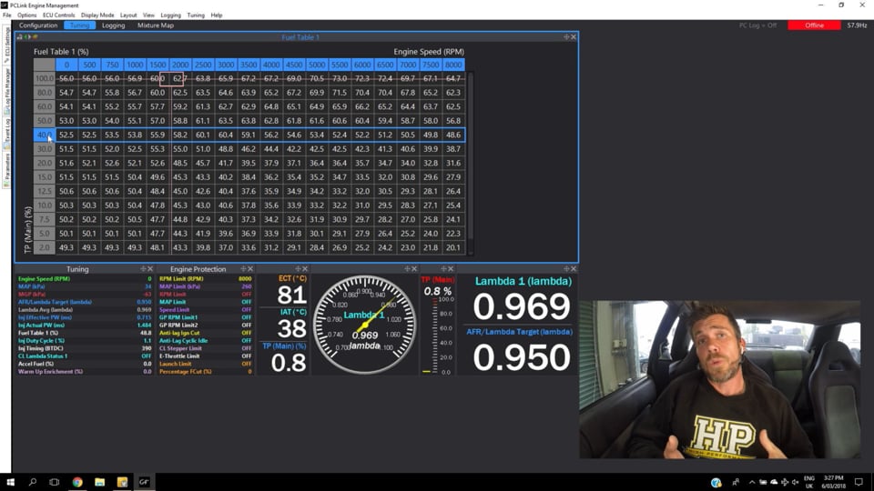
| 07:26 | So here we've got our main fuel table, you can see our parameter there is our throttle position. |
| 07:31 | And we're moving from the bottom of our table to the top, we're going from closed throttle to open throttle. |
| 07:38 | And you can see down around closed throttle, I've got quite tight groupings, quite tight break points, we go zero, two, five, 7.5, 10, 12.5, 15%. |
| 07:47 | Once we get up to 20% you can see I start opening up those break points a little. |
| 07:52 | We go 20, 30, 40, 50, 60. |
| 07:56 | And then as we get to 60% we open them up even further and we've got 60, 80 and 100. |
| 08:01 | So what I'm trying to do there is just set my break points to match the way the air flow varies through that throttle body. |
| 08:08 | And if we didn't do that, if we simply set break points every 20% throttle opening, what we're going to find is it would be very very difficult to control the fuel delivery down in the idle and cruise areas and that's going to end up with us either too rich or too lean with it basically impossible to get the air fuel ratio where we need it reliably and consistently. |
| 08:31 | Alright I'll just head back across to my notes for a second. |
| 08:35 | OK so with the turbo application, as I've said we add some complexity there because the air flow is going to vary depending on the boost pressure as well as our throttle position. |
| 08:48 | So we need a way of varying our fuel delivery based on our manifold pressure. |
| 08:54 | As well as our throttle position. |
| 08:56 | So this sounds a bit tricky. |
| 08:57 | We've now essentially got another parameter thrown into the mix where we're now not just dealing with a three dimensional fuel table where we're looking at our fuel versus throttle position and RPM. |
| 09:10 | We also are looking at it in four dimensions really. |
| 09:12 | We're also considering manifold pressure. |
| 09:15 | So we need to be able to adjust the fuel delivery as we change the boost. |
| 09:19 | But more than that we also may want to track a different target air fuel ratio as our boost pressure changes. |
| 09:26 | So what I mean by this is we may potentially target a leaner air fuel ratio at five to seven psi of boost compared to what we would be targeting at 15 or 20 psi. |
| 09:38 | So that's the consideration we need to keep in mind. |
| 09:41 | So any time we are tuning a individual throttle body turbo engine, one of the key parameters that we need to keep in mind here is the background fuel equation that the ECU is going to use. |
| 09:55 | And again we'll just jump across to my laptop software here for a moment. |
| 09:59 | Actually while I'm talking here, we'll just get our engine up and running so it can warm up a little bit. |
| 10:03 | So if we go through, and this is obviously specific to the way Link do it, I'm going to go through to our fuel main page. |
| 10:12 | And the key point here that we're looking at is the equation load source. |
| 10:17 | So this is just the way Link describe it. |
| 10:19 | And what we've got here, it's the equation that we're using and this is the common equation that we would normally use in a Link ECU for most engines, is load equals MAP. |
| 10:31 | What this means in a nutshell is that if we double the manifold pressure, in the background the ECU is going to double the fuel supply. |
| 10:42 | So this just works on the basis that if we double the manifold pressure, all things being equal, if we wanna achieve the same air fuel ratio, as we double the manifold pressure, we need to double the amount of fuel being delivered through the injectors. |
| 10:55 | And if we do that, that's going to maintain, or it should ideally maintain a consistent air fuel ratio. |
| 11:01 | So this is the background equation that's going on. |
| 11:03 | A lot of other ECUs will have a manifold absolute pressure compensation table instead of this. |
| 11:10 | And normally that will be set up as a 1:1 table. |
| 11:13 | So as we double our manifold pressure, we simply double the amount of fuel being delivered. |
| 11:18 | This has the effect of reducing some of the work we need to do in the actual fuel table, it reduces the requirement for us as tuners to actually double that fuel as the boost pressure increases, that simply happens sort of automatically in the background. |
| 11:35 | So for this system on a turbo charged engine, it is essential that we have our load equals MAP running. |
| 11:42 | OK so with that being said, let's have a look at the solutions that we have available to this problem. |
| 11:52 | And there are a few solutions here, there are actually three solutions that I'm going to talk about. |
| 11:57 | And really this is gonna come down to there is no right or wrong way of doing this. |
| 12:02 | It really just comes down to the ECU you're tuning and your own personal preference in a lot of ways. |
| 12:08 | We're gonna start with the way that we're using here which is in the Link ECU at the moment, we are using an injection time based fuel model. |
| 12:20 | So let's just jump into my laptop screen again for a moment. |
| 12:23 | So our fuel equation mode at the moment, you can see this is set to traditional. |
| 12:28 | And this is Link speak for an injection time based fuel model. |
| 12:33 | So what we have here, and this is pretty common in injection time based ECUs. |
| 12:38 | We have a master fuel number, we can see that's four milliseconds. |
| 12:41 | And essentially what this means is that if we have a number in our main fuel table here of 100%, and we're running at 100 kPa, before any of the background compensations are applied, that would mean that our injectors would be open for four milliseconds. |
| 12:57 | So the numbers inside our main fuel table here that we're looking at, these are simply percentages of our injector master pulse width. |
| 13:06 | Let's just head back as well 'cause there's one more aspect that's really important here. |
| 13:11 | Which is our open loop lambda table. |
| 13:14 | So this is another function that the Link includes. |
| 13:16 | And in this mode, how we're running this at the moment, with our injection time based fuel model, and the open loop lambda table, this is really really close to how a volumetric efficiency based fuel model works. |
| 13:30 | It's really almost a cross over. |
| 13:33 | The only difference really is that we're not taking into account the engine size or the injector flow characteristics and hence the numbers back over here in our fuel table, these don't have any representation to accurate volumetric efficiency numbers. |
| 13:49 | But the system works really similar. |
| 13:50 | So how this works here, we've got our main fuel table, we've got throttle position on our load axis as we've already discussed. |
| 13:58 | But the magic part, how this works in order to maintain our air fuel ratio as our manifold pressure changes, we'll head across to our air fuel ratio lambda target table. |
| 14:09 | So in this table we can see that the important key is that the load axis for this table is now set to manifold pressure. |
| 14:19 | So we've got our main fuel table that is working in throttle position terms. |
| 14:24 | And we've got our overlay table here, our lambda target table which is manifold pressure. |
| 14:29 | So this allows us the ability to adjust the air fuel ratio that we want based on our manifold pressure. |
| 14:36 | So it's important when we're doing this to make sure that we actually set these targets realistically. |
| 14:41 | We set the targets to what we actually want the engine to be running. |
| 14:45 | So for example you can see that a large chunk of this table here is set to a target of lambda one. |
| 14:51 | This is predominantly a street engine. |
| 14:53 | So it's gonna spend a lot of its time cruising. |
| 14:55 | So we want to get good fuel economy. |
| 14:57 | And particularly with these RB26 engines, we're constantly going to find that when we're out on the open road cruising, we're actually going to be sitting up around this 100 kPa area or even marginally up into positive boost, even though we've got very very little throttle opening. |
| 15:12 | So this is why I've got quite lean lambda targets there, even at 100 kPa. |
| 15:18 | So what we're going to look at for today's test as well, we're going to look at two separate boost points. |
| 15:23 | We're gonna look at our wastegate boost setting, which gives us around about 10 psi peak or about 170 kPa. |
| 15:30 | So this will have us operating up around this area of our target table. |
| 15:36 | And then we're also going to increase our boost pressure so you can see how this whole system works nicely and automatically. |
| 15:42 | And our peak boost pressure setting is 220 kPa, which for those who work in psi gives us around about 18 psi gauge pressure. |
| 15:51 | You can see that I've just brought those targets down a little bit there. |
| 15:54 | We've gone a little bit richer at 0.8 lambda. |
| 15:57 | So this is the background work we need to do. |
| 15:59 | We need to set up our fuel mode, we need to make sure we've got our fuel load equation set to load equals MAP. |
| 16:06 | We need to set up our main fuel table in relation to throttle position, and then we want to set up out air fuel ratio target table, like we've done there with manifold absolute pressure. |
| 16:17 | Now we are really focusing solely on the fuel side of this. |
| 16:21 | I will just quickly jump across though and show you that that ignition side of things really is quite conventional, we're not gonna deal with this again, we're just simply using a conventional manifold absolute pressure axis for our ignition table. |
| 16:35 | So it's the fuelling that's really the tricky bit with an individual throttle body engine. |
| 16:40 | OK so with that all set up, let's actually get the engine up and running here on our Mainline dyno and we'll go through and we'll have a look at how we can make some tuning changes. |
| 16:49 | And really for those of you who are familiar with tuning turbo charged engines, this actually becomes incredibly easy. |
| 16:56 | Because all we're doing is setting our throttle position and we can adjust our fuel delivery to suit. |
| 17:06 | So let's just get ourselves up and running here. |
| 17:10 | We'll go to 2500 RPM here on our dyno. |
| 17:18 | If I can actually get everything running, just give me a moment here and I'll just change one of our settings on our dyno. |
| 17:27 | Tacho trim will make my life a little bit easier. |
| 17:29 | OK so at the moment I'm at 15% throttle. |
| 17:33 | I could probably close the throttle down a little bit beyond this but realistically that's fine for the purposes of our demonstration here. |
| 17:41 | What I might do, we've got our manifold pressure here but it's probably a little bit small for most of you to see so let's just bring that up here. |
| 17:54 | Just bear with me and I'll just add our manifold pressure into our digital readout. |
| 17:59 | So you'll actually be able to see the relationship between our manifold pressure and our throttle position. |
| 18:07 | Alright so that'll now display at the bottom. |
| 18:09 | So we've got our lambda target here. |
| 18:11 | This comes from our AFR target table. |
| 18:13 | We've got our measured air fuel ratio, this is coming from a wide band air fuel ratio sensor, and then we've got our manifold pressure. |
| 18:20 | So at the moment we're in vacuum, and the process is simply the same as tuning any speed density system. |
| 18:26 | What we can do is simply make adjustments to the numbers in our fuel table until we're on target. |
| 18:31 | And all I'm going to do is just climb up this column here using the dyno in steady state and adjust the fuelling until I'm on my target. |
| 18:39 | We can see that at 20% throttle we're still in vacuum there at 89 kPa. |
| 18:44 | We'll just increase our throttle again. |
| 18:46 | And we come up to 30%. |
| 18:50 | So you can see now we're moving into positive boost pressure, we're at about 106 kPa, so we're just starting to cross over into positive boost. |
| 18:57 | And that's why you're starting to see our lambda target fluctuate a little bit here. |
| 19:01 | So we're sitting at 0.98, you can see we're pretty much right on that there. |
| 19:05 | So we'll just go through, we're a little bit lean there, oh no pretty good actually, maybe just add a little bit of fuel there. |
| 19:13 | And again we're just going through, opening our throttle, and it's very easy for us to really accurately here just access each of the individual zones, because we're only worrying here about the throttle position, we're not worrying about our manifold pressure. |
| 19:29 | That's just happening all in the background automatically for us. |
| 19:33 | So we can see we're up to 129 kPa, I'll just go a little bit further, 80% throttle, we're a little bit rich at that point, so we'll just pull a little bit of fuel out, and then we can go all the way through to wide open throttle, 132 kPa, and again we're a little bit rich. |
| 19:48 | That's as simple as it is, and we're going to basically go through and repeat that process. |
| 19:54 | So all we really need to do is worry about that one single parameter for our fuel table. |
| 19:59 | And provided the background calculation is already set up, everything's going to track. |
| 20:04 | So with this system just like a true volumetric efficiency based system, if we head back to our air fuel ratio target table, no let's try and get our air fuel ratio target table not our ignition table. |
| 20:17 | If we head to our air fuel ratio target table and we actually make a change to our air fuel ratio target in this table. |
| 20:25 | Just like in a VE based fuel system, it's actually going to affect the injector pulse width and hence our actual fuelling's gonna change. |
| 20:32 | So let's just demonstrate that, we'll just come back up to our set point of 2500 RPM. |
| 20:40 | We'll come up to this point here in our air fuel ratio target table. |
| 20:44 | You can see we're a little bit rich but we're pretty close, we're about 1% richer than our target. |
| 20:49 | Our target at the moment's lambda one. |
| 20:51 | Let's just change that to 0.9 and straight away you can see that our measured air fuel ratio actually tracks that change. |
| 20:58 | So this is the important part, this is what the open loop AFR table does in the Link ECU when we've got that enabled. |
| 21:05 | It actually affects the overall amount of fuel being delivered. |
| 21:09 | And before we move on and have a look at some wide open throttle ramp runs there, I just want to explain to you why that's the case. |
| 21:14 | For those of you who have been through our EFI tuning fundamentals course, for me one of the really key takeaways from that course is learning how to apply a correction factor so that if your air fuel ratio is too rich or too lean compared to your target, you can simply calculate straight away a correction factor that you can apply to correct that error in one adjustment. |
| 21:38 | And this is exactly what that open loop air fuel ratio target is doing in real time as the engine is operating. |
| 21:44 | So what it's doing is it's looking at our desired air fuel ratio that's coming from our target, and what it's doing, is it's always assuming that the fuel table is tuned to lambda one or 14.7:1 So what it's doing is it's taking the air fuel ratio that it assumes we have, in this case lambda one, and it's dividing that by the air fuel ratio or lambda target we want, our target lambda, let's say that's 0.8 So if we divide one by 0.8 that'll give us a multiplier of 1.25 So in other words if we were running at lambda one, and we really wanted to be running at lambda 0.8 if we multiplied that amount of fuel we were providing by 1.25, in other words add 25% more fuel, we will achieve our target of 0.8 lambda. |
| 22:29 | So that's the whole principle behind this and this is why we can track our air fuel ratio target changes while we're using a throttle position based fuel table. |
| 22:40 | OK so with that our of the way now, we're gonna have a look at a couple of wide open throttle ramp runs. |
| 22:45 | So first of all let's just have a quick look back in our fuel table. |
| 22:49 | So this is the bit that's a little hard for tuners to get their head around if they're used to tuning conventional turbo engines. |
| 22:55 | The whole time that we are doing a wide open throttle ramp run, we are only going to be operating in that 100% throttle row of our fuel table. |
| 23:05 | So for our first run here, what I'm going to do, as I said I'm gonna perform two runs. |
| 23:10 | I just wanna check, OK so I've just basically closed down our wastegate duty cycle table here for our very first run so we'll be running on our wastegate spring pressure. |
| 23:21 | That should be as I said, around about 10 psi. |
| 23:23 | Let's head across to our Mainline dyno, and we'll get our first run underway. |
| 23:28 | So on the dyno screen at the moment, we've got three pieces of information. |
| 23:32 | At the top we've got our air fuel ratio in lambda. |
| 23:34 | I've got a reference line in there at 0.8 Remember our target here is 0.82 So we should be a little bit above that line. |
| 23:42 | Below that we've got our manifold absolute pressure. |
| 23:45 | This time we should be seeing around about 170 kPa peak and then of course we've got our power at the bottom. |
| 23:51 | Alright so with that all out of the way, let's get our run underway. |
| 24:18 | Alright so everything worked pretty nicely there, you can see that our air fuel ratio tracked just above that white reference line as I said it should do. |
| 24:27 | It's always nice when it actually works the way it should. |
| 24:29 | Unimportant for our demonstration today, but we've got 213 kilowatts at the wheel or 286 horse at the wheels which is shown at the bottom, and then we've got our manifold pressure, which has done pretty much exactly what I was expecting it to do. |
| 24:42 | Let's just dive into our laptop software and we'll just have a better look at exactly what's going on here. |
| 24:48 | So let me just zoom in a little bit. |
| 24:50 | So on the groups that we're looking at here, at the top we've got our engine RPM, we've got our manifold pressure below that. |
| 25:02 | Again if we just sort of look at our peak point. |
| 25:04 | There we're at about 170 kPa. |
| 25:06 | Our next group down is the important one though, we've got our air fuel ratio lambda target versus our measured lambda. |
| 25:14 | So the darker blue is our target and the lighter blue that's moving around a little bit is our measured lambda. |
| 25:21 | So the point is, you can see at the start of the run we're at 100% throttle, we're actually a little bit rich there, but let's look at a point as we just start to ramp up. |
| 25:28 | So we're within 1% of our target. |
| 25:31 | As we ramp down to our target you can see we're always pretty well right on that target. |
| 25:36 | We get to 156 kPa, 3500 RPM, we're on our target of 0.82 and you can see that while it does move around, we're right on that target the whole time. |
| 25:47 | So the ECU is doing its job even though we are only running through that one row of our throttle position fuel map. |
| 25:56 | Even though you've seen there our manifold pressure at the start of the run was 108 kPa, and we're seeing 170 kPa at the end of the run OK so that makes it really easy. |
| 26:06 | Obviously when we are making tuning changes, if we were a little rich or a little too lean, makes it really easy to highlight exactly which cell we need to change. |
| 26:16 | What we're going to do now though is let's just head back into our wastegate target table, wastegate duty cycle table. |
| 26:22 | This is a pretty basic open loop table so all I'm doing is just extending that table out into the areas we were just running in. |
| 26:31 | So we're gonna do our second run now. |
| 26:33 | So for our second run we now should be targeting approximately 220 kPa. |
| 26:37 | That's a pretty big jump from the 170 that we just ran. |
| 26:40 | And we are expecting now that our air fuel ratio should still track exactly where we want it to be. |
| 26:53 | So let's just bring up the air fuel ratio target table. |
| 26:56 | So remember this time we're at 220 kPa, we're gonna be targeting a little bit richer so hopefully this time we should be on our reference line that I've just put in there. |
| 27:05 | So what I'll do is we'll just save this run, we'll call that test two. |
| 27:10 | That run's gonna stay up on our dyno screen while we perform this second run by the way as well so you'll be able to see it overlay. |
| 27:17 | Particularly the boost and the air fuel ratio in real time. |
| 27:21 | So let's get back up into fourth gear on our dyno here. |
| 27:27 | And we'll head across to the dyno screen and we can start our second run. |
| 27:56 | Alright so that's also done pretty much exactly what I was expecting to demonstrate. |
| 28:01 | So you can see our power's shot up to 262 kilowatts, 351 horsepower at the wheels which is no big surprise with that jump in boost. |
| 28:08 | We can see that jump in boost here, we're right on our 220 kPa target so that's doing its job. |
| 28:13 | The important thing though is our air fuel ratio. |
| 28:15 | So we've got a little bit of a lean hole here, but nothing really too major. |
| 28:20 | What I wanna concentrate on is for the most part, through this run we're on our target. |
| 28:24 | Remember we were targeting 0.8 this time. |
| 28:27 | But there's a little bit more to that. |
| 28:29 | So let's jump into our laptop software for a moment. |
| 28:33 | And we'll have a look at what we've got to display. |
| 28:37 | So again ignoring for a moment we've got a little bit of a lean spot there which I'm not going to concentrate on. |
| 28:44 | For the most part we are right on our target. |
| 28:47 | So everything has tracked that background calculation in the ECU as we've increased the boost pressure, in the background it's done two things. |
| 28:55 | First of all as we've increased the boost pressure, it's also naturally increased the fuel delivery. |
| 28:59 | Remembering that as we double air density, we need to double the fuel delivery in order to achieve the same target air fuel ratio. |
| 29:08 | But of course this time we're not trying to achieve the same target air fuel ratio, we also wanna be richer, so that's where that open loop air fuel ratio table has come in. |
| 29:17 | That's added some additional fuel as well. |
| 29:19 | Now the point that I wanted to show you though, is right in the top end here, and it's not too dramatic because we are only running 220 kPa here, we're starting to see that our air fuel ratio is now actually drifting a little bit rich. |
| 29:34 | And this presents a problem for us. |
| 29:36 | The reason that presents a problem is because if we want to correct that rich area, we're going to have to go back to our fuel table and we're going to have to remove a little bit of fuel from this main fuel table in the areas that were a little bit rich. |
| 29:52 | That's going to also have the effect though of now leaning out the air fuel ratio when we're at our low boost setting. |
| 30:00 | So we've got no easy solution there, we can't fix our high boost problem without affecting our low boost problem. |
| 30:09 | And this is the issue we do see when we're using throttle position for our main fuel table. |
| 30:15 | And the problem comes in when we start to push the turbochargers harder. |
| 30:21 | And what we see is that the back pressure starts to build. |
| 30:25 | So basically the turbocharger starts becoming less efficient, it's not flowing so well. |
| 30:30 | So when we're doing this, what we're gonna find is from our minimum wastegate pressure that we can run, up to maybe 15 or 16 psi of boost, depending on your turbocharger's size, everything's gonna track nicely. |
| 30:43 | As you increase the boost pressure, the air fuel ratio is just going to magically do exactly what you ask it to do. |
| 30:49 | but as you start increasing the boost further and further and the turbocharger starts to present a bit of restriction to exhaust flow, what you're going to then find is that at higher RPM, at those higher boost settings, you're going to start seeing the air fuel ratio taper off richer. |
| 31:05 | So as I said here we've only gone from 170 to 220 kPa. |
| 31:08 | If we'd gone up to 250 or 260 kPa, that situation we've got there is going to become much more prominent. |
| 31:16 | So of course we need a way of dealing with that situation. |
| 31:20 | That's pretty easy though, we've got some options there which we're now going to look at. |
| 31:25 | We'll just jump back into our laptop software. |
| 31:27 | And what we can do in order to deal with that is we can add another compensation table. |
| 31:32 | So in this case I'm going to go to our 4D fuel table which I've already set up. |
| 31:37 | And this engine has been previously tuned. |
| 31:40 | I just chose to eliminate this trim just to show you the situation. |
| 31:44 | This 4D table basically provides a compensation in terms of a percentage change to our main fuel delivery. |
| 31:50 | You can see here we've got our load axis set to manifold pressure. |
| 31:54 | That's an essential part of this. |
| 31:56 | And what we can see here is that at high RPM and higher boost pressure, we're actually starting to trim a little bit of fuel out. |
| 32:05 | At 6000 RPM we're trimming out 1% as we move to 6500 it's minus three and then finally at 7000 RPM and above we're now trimming out minus 4%. |
| 32:16 | So prior to actually beginning this webinar, that calibration, that table extended down into our 220 kPa row as well. |
| 32:26 | And that fixes that little rich area that we were seeing. |
| 32:31 | So of course what we would find is that if we were going to run boost pressures above 220 kPa, it's likely that we would end up needing to remove further fuel from these zones as we continue to increase boost and we'd continue to find that the turbo charger becomes more and more restrictive. |
| 32:50 | So we might end up with a table that looks something like that. |
| 32:54 | So that's the basis for individual cylinder throttle body turbo charged engine mapping, and those are kind of the tricks. |
| 33:02 | So really the main aspect is we need to use the throttle position as our main fuel table axis. |
| 33:11 | We need to have our open loop air fuel ratio table turned on if we're running in traditional mode. |
| 33:17 | We also need to make sure that our main fuel equation in the link is load equals MAP so that it can do that automatic compensation for the fuel delivery as our manifold pressure varies. |
| 33:27 | And then what we're going to do is simply tune the engine running throttle position for our fuel table. |
| 33:32 | We've got our air fuel ratio target set to what we actually want to achieve. |
| 33:36 | And then as we increase the boost and we find that the turbo charger starts to become restrictive, we can use our 4D compensation table that we've just looked at in order to make further corrections. |
| 33:47 | OK so that's one method that we can use to provide that tuning. |
| 33:51 | We're going to look at a couple more though, and I just want to mention here, is a good time to stop and say that we will be moving into some questions and answers shortly. |
| 34:01 | So if you do have any questions, I know this is a technical topic, so it's quite likely that you guys are gonna have some questions about this, please feel free to ask them in the comments or in the chat and I'll do my best to address them. |
| 34:14 | OK so that's the first option. |
| 34:16 | This is the original option that I used on the Link range of ECUs because at the time they didn't have their modelled or in other words their volumetric efficiency based fuel mode. |
| 34:28 | Traditional was all we had back then, the ECUs originally were only injection time based ECUs. |
| 34:34 | So that's why I became familiar with that option. |
| 34:36 | But in more modern ECUs you can now achieve exactly the same aim by using the VE fuel model. |
| 34:46 | And in this case it basically really does exactly what we've just looked at. |
| 34:51 | As I kind of alluded to at the start of this, that traditional mode using Link's open loop air fuel ratio target overlay table really has the ECU responding very similar to a VE fuel model. |
| 35:04 | Albeit the numbers in our fuel table do not represent true volumetric efficiency. |
| 35:10 | They'll show the same shape as a VE curve but they are not representative of VE. |
| 35:14 | So of course now with Link having their modelled fuel equation which is a VE fuel mode, we can use that instead. |
| 35:21 | So this requires us to be a little bit more particular, the ECU will need some information about the injector size, it'll need information about the fuel we're running on such as the density, the stoichiometric air fuel ratio et cetera. |
| 35:33 | And in a volumetric efficiency based fuel mode, the air fuel ratio target table naturally acts to adjust the fuel delivery. |
| 35:43 | So the way we've set this up is exactly the same. |
| 35:46 | our volumetric efficiency table is set up based on throttle position. |
| 35:50 | Our air fuel ratio target table is set up based on manifold absolute pressure. |
| 35:55 | And then of course the tuning is exactly the same. |
| 35:57 | The only real difference is this time the numbers that we are putting into our fuel table should really be representative of true VE. |
| 36:05 | We also need to keep in mind we will still need, under those circumstances to potentially use a 4D compensation table in order to correct the air fuel ratio at high boost level, high RPM, where the fuelling starts to move a little bit rich which it naturally will. |
| 36:24 | The last option I want to go through is one that hopefully will explain the situation. |
| 36:31 | I know that that open loop air fuel ratio target table confuses a lot of tuners. |
| 36:36 | It is a little bit abstract and I know a lot of tuners do struggle to get their head around that system. |
| 36:42 | So what I'm going to do is go through another mode of setting this up so that we can see how we could do this if we didn't have an open loop air fuel ratio target table. |
| 36:52 | So again let's just jump into my laptop software here. |
| 36:56 | And what we're going to do is we're going to do exactly the same, we're going to start with our main fuel table tuned relative to throttle position. |
| 37:05 | Now what we'll do is we'll jump into our fuel main settings. |
| 37:08 | We'll just highlight a couple of things in our fuel main settings here. |
| 37:15 | OK so the first thing is again a central part of this, we still need to have our load equals MAP fuel equation. |
| 37:22 | That's an essential part. |
| 37:24 | This time what we're going to do though is we're going to disable our open loop lambda target table. |
| 37:29 | So what that means is the AFR target table, let's just head across to it again. |
| 37:35 | The air fuel ratio target table now will have absolutely no impact on our tuning. |
| 37:40 | We can put whatever numbers we want into this table, it'll have zero impact on the actual fuel delivery. |
| 37:47 | In this mode the only use for this table is if we were to run closed loop fuel control which at the moment we're not. |
| 37:54 | So now we can disregard that. |
| 37:55 | So now we've got an ECU that is tuned purely via throttle position. |
| 38:01 | Now the problem with that as we've already discussed is we're not gonna have any way of adjusting our fuel delivery as the manifold pressure changes. |
| 38:09 | So we may be in a situation where we get 100% throttle at maybe 100 or maybe 105 kPa. |
| 38:16 | We could also have exactly the same throttle at maybe 150 kPa and we want very different air fuel ratios. |
| 38:23 | So remember in this situation we've still got that load equals MAP equation. |
| 38:27 | So the ECU will be increasing the fuel delivery as the manifold pressure increases but the aim of the ECU there is just to maintain a consistent air fuel ratio. |
| 38:37 | So now in order to make this work, we need a way of making changes to the fuel delivery based on our manifold pressure. |
| 38:44 | Well that's OK we can do exactly that. |
| 38:47 | What we're going to do is head across to our 4D, if I can find it, there we go, we'll head across to our 4D fuel compensation table. |
| 38:57 | So remembering again this is set up at the moment to make a percentage change to the fuel delivery. |
| 39:02 | You'll see that just as before we've got this axis set up to manifold absolute pressure. |
| 39:08 | And what we're going to do now is assume again just like the open loop air fuel ratio target table does, that the engine is tuned to lambda one everywhere. |
| 39:19 | Now that might be fine down in these areas of the engine's operation down in vacuum where we're in cruise and we want good fuel economy. |
| 39:28 | Certainly it's not gonna be much good up around 220 kPa. |
| 39:31 | So what we can do is make a percentage correction. |
| 39:34 | And this is essentially exactly what the ECU is doing with that open loop air fuel ratio target table in the background without us needing to even think about it. |
| 39:42 | So remember our target at 220 kPa was 0.8 lambda, so let's see how we can figure out what numbers need to go in this 4D compensation table to have exactly the same effect. |
| 39:53 | Remember what we're doing is using our correction equation so what we're doing is taking the air fuel ratio that we have, the measured air fuel ratio. |
| 40:02 | So remembering here for the moment we're simply assuming that we've tuned to lambda one. |
| 40:07 | So we're putting 1.00 in that. |
| 40:09 | Then we wanna divide that by the lambda or air fuel ratio target that we actually want to achieve. |
| 40:16 | The air fuel ratio that we're targeting. |
| 40:18 | In this case remember that's 0.80 OK so the result is that we need to add 25% fuel. |
| 40:27 | So all we need to do there, now that we've made that calculation, is enter a value of 25% in our 220 kPa row. |
| 40:35 | And that's going to have the effect of targeting 0.80 lambda and of course we can basically do that at each point in this table. |
| 40:43 | In this case let's just interpolate that down and we probably would want to also richen that maybe up a little bit as we go higher in boost. |
| 40:55 | So now we've got this compensation table that's doing all of that work in the background for us. |
| 41:00 | And that's going to have exactly the same effect as our open loop air fuel ratio target table. |
| 41:05 | We now also have that same scenario though where we're still going to have our air fuel ratio track a little bit rich as we increase our boost pressure and the turbo charger starts to become restrictive. |
| 41:16 | This time we have the option of directly correcting that within this table in the areas where it is starting to move a little bit richer. |
| 41:25 | So we can just do that directly inside of this table as opposed to in our last example we actually had to bring in this table to control that. |
| 41:34 | Alright guys we'll move into some questions and answers. |
| 41:37 | Hopefully I've done a reasonable job of explaining what is quite a complex topic there. |
| 41:44 | Right so we've only got a couple of questions there. |
| 41:48 | So David has asked, pros and cons to TPS versus MAP. |
| 41:53 | It's not really a case of pros and cons. |
| 41:57 | This is more a case of it's essential in this case to use throttle position as our main load axis. |
| 42:04 | If we use MAP we're gonna get terrible results, it's that simple. |
| 42:08 | In a conventional turbocharged engine though where we are running with a common plenum and a single throttle body, this is where we do have the option, we can run either TPS or MAP. |
| 42:20 | Now conventionally the most common way of doing this is to use manifold absolute pressure obviously as our load axis. |
| 42:27 | This is the way everyone tunes. |
| 42:29 | My own personal preference is that I do see some advantages using throttle position as that load axis even under those conditions and basically replicating what we've just looked at with our 4D mapping. |
| 42:41 | So the reason I like this is because if we look at the system, the way the turbocharger works, it's incredibly good at creating boost. |
| 42:49 | So let's say for example we have tuned our turbocharged engine and it's producing 20 psi boost at wide open throttle 4000 RPM. |
| 42:59 | We've got our air fuel ratio tuned right on our target, everything's running perfectly. |
| 43:04 | Now let's look at what happens if we're running at 4000 RPM steady state on our dyno and we start closing down the throttle body. |
| 43:11 | As we close our throttle, the boost does no instantly drop. |
| 43:14 | What we're going to find is that the wastegate's going to start closing down, and that's going to have the affect of driving the turbo charger a little bit harder in order to maintain that 20 psi. |
| 43:25 | So depending on a range of parameters, our turbo size et cetera, we might find that we still retain that 20 psi of boost pressure until we get down to maybe 70, maybe even 60% throttle or thereabouts. |
| 43:37 | And if you're tuning using manifold absolute pressure as our load axis, what you're going to find is that as you close down that throttle, we're still staying in that one fixed cell, we're still staying in the 20 psi to 40 kPa zone of our fuel table. |
| 43:52 | And you're going to find that as you close down the throttle because the turbo's working harder, it's adding more restriction to the exhaust flow the actual air flow through our engine is reducing. |
| 44:00 | And by virtue of that we're gonna find that we go richer. |
| 44:04 | So while it's not the perfect way of describing exactly what's going on, I do find that using throttle position actually does a better job of, how would I put it, a better job of modelling maybe the volumetric efficiency of the engine as we go through that exact same scenario. |
| 44:23 | Andy has asked, is there a reason to not do speed density primary and alpha n secondary? I mean I guess you could do it either way. |
| 44:33 | The way I've gone through and tuned that there, just let me form a good answer for you here Andy because I think this actually is an important thing as I've been thinking about this. |
| 44:46 | So I'll go back to a very early ECU as an example that I tuned, which is the HKS F-CON V Pro. |
| 44:54 | And at the time this was quite a popular ECU I was doing on a lot of Nissan GT-Rs because they came as a plug and play kit. |
| 45:01 | So the way the the F-CON V Pro dealt with the individual throttle body turbo application on the GT-R was with two separate maps. |
| 45:09 | They had a throttle position map and they had a manifold absolute pressure map. |
| 45:15 | And the way they integrated those two maps was quite confusing and you go to a situation where you could be in a place in the map where you were too rich and then it became confusing as to which map should you adjust in order to get the air fuel ratio where you want it? With the F-CON V Pro there wasn't always a clear guide as to which way to do it. |
| 45:36 | So the way that I've just gone through gives us a really clear indication there. |
| 45:41 | We've got that background fuel equation working. |
| 45:43 | We know how to calculate what additional percentage fuel we need relative to manifold pressure, that we need to add as our boost pressure increases. |
| 45:53 | And then we can simply tune on throttle position and everything else is just going to take care of itself in the background. |
| 46:01 | So to answer your question more specifically, if you flipped it 'round on its head and did it the other way around, I don't see an easy way of doing that. |
| 46:08 | I could be overlooking something here. |
| 46:10 | Because you're gonna be in that situation where if you main fuel table is on manifold pressure and you're using throttle position as a secondary table, it gets a little bit messy because you're not necessarily gonna have a clear indication of where you should be removing fuel or adding fuel. |
| 46:27 | Brandon has asked, is it possible to have the ECU auto calculate the fuel correction in the logging section so if you have a dip in the fuel between your target and you lambda reading, you can correct it for that spot on the graph rather than playing with the numbers in the fuel table? Yeah you can quick trim the fuel table. |
| 46:43 | But essentially it is really the same as what we just looked at. |
| 46:48 | So I think even with ECUs where they have an autotune function, it's really important to understand what that functonality is doing. |
| 46:58 | So quick trim in the Link ECU maybe quick lambda in the Motec ECU, this will automatically make adjustments to the fuel table values based on an error that we've got in our log. |
| 47:10 | There's also the mixture map function of the Link ECU but that's getting a little off track. |
| 47:13 | All it's doing is doing exactly that same calculation that I just did. |
| 47:18 | It's looking at the measured air fuel ratio. |
| 47:20 | So the air fuel ratio that we currently have. |
| 47:22 | And then it's dividing that by our desired or target air fuel ratio and then that's the percentage change. |
| 47:28 | So all you need to then do is multiply the number in our fuel table by that percentage. |
| 47:33 | So regardless whether you're going to use those autotuning functions, think, it's going to make you a better tuner if you actually understand that math behind that. |
| 47:42 | It's really simple. |
| 47:44 | Just understand what the ECU's actually doing and why. |
| 47:47 | Scary Fast has asked, I realise this may be ECU centric but with Link's load option of barometric air pressure divided by manifold absolute pressure cross over, would that be an alternative option for boosted engines using ITBs? You could possibly use that mode. |
| 48:06 | It definitely isn't the one that I would suggest. |
| 48:11 | That mode, it's not one that I ever use to be honest. |
| 48:14 | But if my memory serves correct, basically what it will do is look at barometric air pressure until you move up into positive boost pressure and then it'll move into a map based fuel model. |
| 48:25 | It's still gonna have all of those same problems that I've talked about there at the start of this webinar, so it is not one that I would use for a boosted ITB engine. |
| 48:36 | I know that in the help file Link do give some suggestions of when certain fuel modes would be suitable, but yeah definitely the way I've described it, I guarantee you this is the way that you will get the best and most consistent results with the Link ECU in particular. |
| 48:54 | And I'll just cover as well, the Nissan factory ECU gets around all of these complexities by simply using a pair of mass air flow sensors. |
| 49:03 | And I think in the aftermarket we tend to look down our nose on mass air flow sensors. |
| 49:09 | Almost inevitably our aftermarket ECUs all work on the speed density principle. |
| 49:14 | But this is one of those areas where we really see that a properly set up, properly calibrated mass air flow sensor actually makes a hell of a lot of sense and makes the tuner's job easier. |
| 49:25 | Rather than us needing to, or the computer needing to calculate the mass of air entering the engine and using a bunch of these compensation tables. |
| 49:34 | We haven't even got into things such as air temperature compensation as well. |
| 49:39 | So we're using all of these compensation tables to try and do the best job possible of modelling the actual air flow under these changing conditions. |
| 49:48 | The mass air flow sensor simply measures the mass of air entering the engine. |
| 49:52 | That's the bit that the ECU needs to know in order to schedule the fuel delivery and the ignition timing. |
| 49:57 | So if it knows directly the mass air flow from a mass air flow sensor, its job is actually really really easy. |
| 50:03 | Alright guys that has brought us to the end of our webinar today. |
| 50:07 | So thanks everyone for joining. |
| 50:09 | As usual for our HPA members, if you do have any further questions, please ask those in the forum and I'll be happy to answer then in there. |


