169 | Is Your Mass Airflow Sensor Big Enough?
Summary
For those tuning factory ECUs, or standalone ECUs that utilise a MAF sensor for the load calculation, a common problem when modifying the engine for increased airflow, is exceeding the flow capability of the stock MAF. When this happens, the MAF can no longer report increased airflow and it’s impossible to correctly control fuel and ignition timing. In this webinar we’ll look at how you can know when your MAF is too small and solutions to this problem. For this webinar we’ll be using a turbocharged Toyota 86 using a MoTeC M150 ECU.
| 00:00 | - It's Andre from High Performance Academy. |
| 00:02 | Welcome along to this webinar, where we're going to be talking about the mass air flow sensor. |
| 00:07 | And we're going to find out what you need to know about mass air flow sensors, particularly if you are modifying a factory engine that is already fitted with a mass air flow sensor. |
| 00:16 | And one of the biggest problems you're likely to find is that when you start modifying a factory engine and producing more power, you may get to a position where you're exceeding the flow, air flow, that the mass air flow sensor is capable of registering. |
| 00:31 | Now that's gonna cause you quite a lot of trouble because the ECU really isn't going to know what's going on. |
| 00:37 | So it is a problem that is quite common, and if you don't know what's happening, it can also be pretty confusing while you're sitting there on the dyno wondering why things aren't quite going the way you expect it. |
| 00:49 | So let's get into the webinar. |
| 00:51 | We will, as usual, be having questions and answers at the end of the webinar. |
| 00:55 | So if there's anything that I cover today that you'd like me to explain in more detail or anything generally related to today's topic, please ask those in the comments and the guys will transfer those through to me. |
| 01:07 | So I think we'll probably start with a pretty simple question which is what is a mass air flow sensor? So the mass air flow sensor is probably much more common in the OE world, the factory engine management tuning world, because it is the favoured option when it comes to metering the air flow into the engine by most OE manufacturers. |
| 01:30 | In the aftermarket world, which I'll talk a little bit more in a few seconds, we're much more likely to be using the speed density principle where we can get rid of the mass air flow sensor and instead we run a manifold absolute pressure sensor. |
| 01:45 | So a mass air flow sensor, I've got one here. |
| 01:48 | This is actually a mass air flow sensor from a Toyota 86, so it's the car we're using for today's demonstration. |
| 01:55 | And basically the air flowing into the engine passes through the mass air flow sensor and the mass air flow sensor measures the amount of air flow going past it and then outputs a signal to the ECU that tells the ECU what the mass air flow is. |
| 02:12 | Mass air flow sensors also will include an intake air temperature sensor as part of their construction as well. |
| 02:19 | So this is important because all of the ECUs, all of the OE ECUs calculations both on fuel and ignition timing are based on having an accurate idea of the engine load or in other words what mass of air is entering the engine. |
| 02:36 | So if that calculation of that number that the mass air flow sensor is inputting into the ECU becomes inaccurate, of course we can't expect the ECU to be able to correctly schedule fuel and ignition timing. |
| 02:48 | So this plays havoc with our fuel and ignition control. |
| 02:51 | We can have our engine running lean, we can end up with more ignition timing that we want or expect and obviously the results of both of these can be relatively dangerous. |
| 03:02 | Now because I touched on it earlier, I will just talk about briefly mass air flow versus speed density. |
| 03:10 | And as I've said, speed density seems to be really the choice in the aftermarket where we're using a manifold absolute pressure sensor. |
| 03:17 | For the majority of OE manufacturers, mass air flow sensors are favoured. |
| 03:22 | And I think in the aftermarket, or in the tuning world in general, probably mass air flow sensors actually have a pretty bad reputation that in a lot of ways is unfair and unjustified. |
| 03:35 | I think the part that a lot of aftermarket tuners miss is that when a factory mass air flow sensor is correctly installed and it's also correctly calibrated, it actually does an incredibly good job of giving accurate information to the ECU about the mass air flowing into it, into the engine. |
| 03:53 | And in this way it actually makes the ECU's job really easy, particularly in terms of controlling the fuel delivery. |
| 04:00 | So really the key difference between a mass air flow sensor and a MAP sensor, is with a mass air flow sensor we are directly measuring the mass of air entering the engine, and that's the key part that the ECU needs to know. |
| 04:13 | The speed density system, we're kind of doing this in a roundabout way. |
| 04:17 | Rather than directly measuring it, we're using the ideal gas law to calculate the mass of air entering the engine. |
| 04:23 | Now that works quite nicely and it's obviously pretty well proven. |
| 04:28 | We've been using it for decades in aftermarket ECUs. |
| 04:32 | The problem with it is that in order for it to stay accurate as our operating conditions change, we need to use a bunch of compensation tables. |
| 04:42 | So this actually makes it a little bit more tricky for us to get really accurate control with a speed density system. |
| 04:48 | And really this is one of the key drivers why a lot of OE manufacturers favour the mass air flow sensor in order to get really strict control of the fuel delivery which is essential for meeting emission standards. |
| 04:59 | It's actually easier to do that with a properly calibrated, properly installed and designed mass air flow system. |
| 05:06 | OK so we've looked at a mass air flow sensor. |
| 05:09 | We've got a bit of an idea of what they are. |
| 05:11 | We'll have a quick look now at how this data is displayed or what this data looks like when we're actually looking at it in an ECU. |
| 05:19 | So in this case what we're doing is we're basically translating the output of the mass air flow sensor into an air flow in grams per second or pounds per minute depending on whether your ECU is displaying in metric or imperial units. |
| 05:35 | Before we do that though it is important to know that there are two basic ways that our mass air flow sensor can output a signal to the ECU. |
| 05:44 | Some air flow meters will provide a frequency. |
| 05:47 | So we're looking at the frequency and converting that into mass air flow. |
| 05:51 | The other way is, which is quite typical, is a zero to five volt analog voltage so we've got a voltage into the ECU that simply varies between zero and five volts based on the mass air flow. |
| 06:03 | So let's start by jumping into my laptop screen. |
| 06:05 | So we're using our Motec M150 for this demonstration. |
| 06:08 | Now in a weird turn of events, the Motec M150 actually doesn't use the air flow meter for its fuel calculations. |
| 06:17 | It's an aftermarket ECU which works on the speed density principle. |
| 06:20 | However because this is a plug and play kit for the Toyota 86, it also does interface with all the factory inputs. |
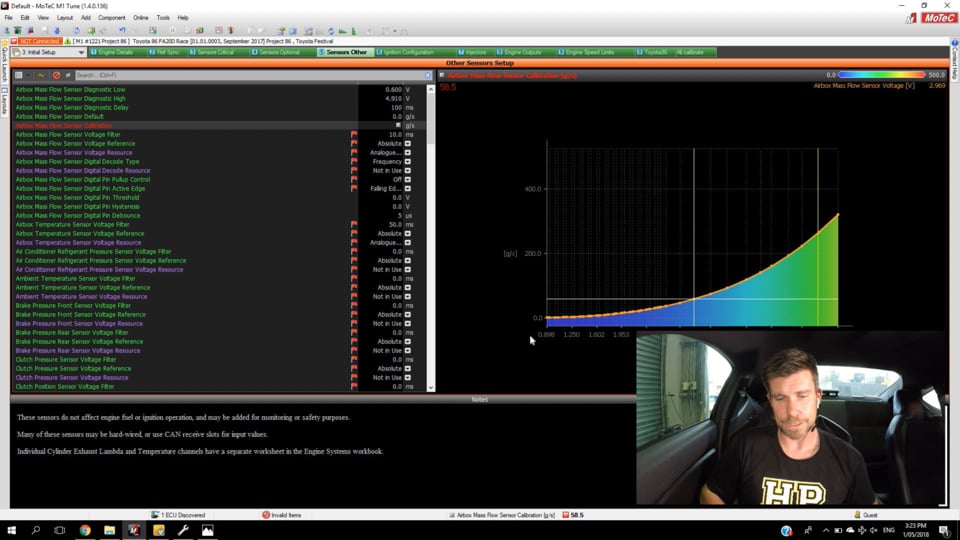
| 06:26 | So in this case here, I'll just highlight this so we can see it, we've got our air box mass flow sensor calibration. |
| 06:33 | So this is what Motec refer to the air flow meter as. |
| 06:37 | So this is connected to the factory mass air flow sensor. |
| 06:40 | And if we look at the calibration, we've got this over on the right hand side here. |
| 06:45 | In this case we have a zero to five volt sensor. |
| 06:48 | We'll show this graphically. |
| 06:50 | So we've got our air flow in grams per second on the vertical axis. |
| 06:54 | We've got our voltage on the x axis which hopefully you can see down there. |
| 07:00 | So the general shape of that curve is pretty typical, this is what we'll also expect, sort of an exponential shape to the curve that we're going to get out of our mass air flow sensor. |
| 07:11 | So we'll just jump back and look at that numerically as well. |
| 07:15 | I'll just go across to the left side. |
| 07:18 | So our first point there is 0.898 volts and we've got one gram per second air flow The point that we're really interested in though for our purposes today is the maximum value that our mass air flow sensor can read, which in this case over at five volts we can see we've got 321 grams per second. |
| 07:39 | There's another couple of aspects which are important here on the setup for our Motec M150 ECU. |
| 07:46 | If we look over on the left hand side here we have a diagnostic value for low voltage and a diagnostic value for high voltage. |
| 07:55 | So in this case if the voltage output from the mass air flow sensor falls below 0.6 volts, this would be reported as faulty by the ECU. |
| 08:03 | We should never be down that low. |
| 08:05 | Likewise if the voltage exceeds 4.91 volts in this case the ECU again would deem the air flow meter to be faulty. |
| 08:12 | So that's what a zero to five volt mass air flow sensor calibration is likely to look at. |
| 08:19 | We'll just jump across to HP Tuners here and we'll have a look on a GM LSV8. |
| 08:26 | The mass air flow sensor's a frequency based air flow sensor. |
| 08:30 | And again we've essentially got exactly the same thing here. |
| 08:33 | We've got a two dimensional table with our air flow meter. |
| 08:36 | In this case frequency instead of voltage and the values relative to that are our air flow, again in grams per second. |
| 08:45 | And again if we look at this graphically we've essentially got exactly the same shape that we just looked at. |
| 08:50 | So this is generally what we expect to see with our mass air flow sensor, regardless whether we are dealing with a mass air flow sensor that works in frequency or in voltage. |
| 09:03 | OK so there are a few important considerations that we need to keep in mind if we are using a system with a mass air flow sensor fitted. |
| 09:13 | The first thing is we need to make sure that the mass air flow sensor is able to read the sort of air flow that we're going to need for whatever power we're going to make with our engine. |
| 09:25 | And this is really the key problem that we see. |
| 09:27 | And again I'll reiterate as we start increasing the power from a factory engine we can get to a point where we're now flowing more air into the engine than the factory air flow meter is designed for. |
| 09:40 | Understandably if the factory producing an engine that's going to produce maybe 300 horsepower, they're going to fit the engine with an air flow meter that can easily measure 300 horsepower worth of air flow. |
| 09:55 | And it's going to have a little bit of headroom in that as well. |
| 09:58 | But for our purposes if we wanna take that same engine that produced 300 horsepower and perhaps now make 600 horsepower, we're going to need a lot more air flow into the engine to double the factory power and chances are we're going to exceed the air flow measurement capability of the factory MAF sensor. |
| 10:17 | Likewise we've got another problem which sort of happens at the other end of the spectrum. |
| 10:22 | And we're going to talk a little bit more about this later in the webinar. |
| 10:25 | We may also find if we start modifying the mass air flow sensor, fitting the mass air flow sensor into a larger measurement tube which is a common option, again, we'll talk about it shortly, we may find that while this now allows us to measure the mass of air that we need at full load, maximum power, we may get to a situation where that we struggle to get really good measurement of the small amounts of air flow that we're going to see at idle. |
| 10:55 | So there's two ends of the spectrum that do need to be considered when we are considering the air flow meter that we've got fitted to our car. |
| 11:02 | OK so what is going to happen if we've got a mass air flow sensor that is too small and we're basically running out of measurement range on that air flow meter. |
| 11:15 | So what's going to happen is that that air flow meter is going to peg the output at whatever the maximum, either voltage or frequency from the air flow meter is. |
| 11:25 | So what that's going to do is basically limit the air flow input into the ECU. |
| 11:31 | So the ECU is going to be seeing a fixed amount of air entering the engine, even though the actual air flow into the engine may be significantly larger than that. |
| 11:42 | So it makes it obviously impossible for the ECU to then correctly calculate what fuelling to supply and what ignition timing to deliver. |
| 11:50 | So the problem as well, we often see this on turbo charged engines or supercharged engines as we increase the boost, we get to a point where everything's been operating quite nicely. |
| 12:01 | We've got good control over our fuel delivery, we've got good control over our ignition timing, then we peg the mass air flow sensor, we can't measure the increase in mass air flow as we further increase the boost, so we start finding that our air fuel ratio begins to drift lean. |
| 12:17 | And the reason for this is we're supplying more air but the ECU doesn't know about it so it's maintaining the same fuel delivery and likewise and possibly more dangerous the ignition timing trend that we normally see is that as we increase load onto the engine, we're going to need to retard the timing. |
| 12:35 | So in other words as we increase the boost from say 10 psi to 20, we're likely to need to retard the timing quite significantly in order to either achieve MBT or probably more likely if we're running on pump gas, to stay away from detonation. |
| 12:51 | So this is the problem, we end up with a lean air fuel ratio with too much ignition timing, pretty much the perfect recipe for our engine suffering from knock OK so with that in mind, what should you be looking for or how do you notice whether your air flow meter is too small for your application? Now hopefully if you've done your homework this is something that you should know about before you go anywhere near the dyno and that's certainly going to save you a lot of time. |
| 13:21 | And particularly if you go on the dyno, find that you've maxed out your air flow meter and you need to replace the air flow meter, you're going to end up wasting a lot of time and money on dyno time that's going to need to be repeated once you've got that problem sorted. |
| 13:34 | Obviously as I've just discussed as well, you do potentially get into a situation where this may be dangerous for your engine as well if you don't notice quickly enough. |
| 13:43 | So hopefully you're going to know whether your air flow meter is gonna be sufficient for your aims. |
| 13:49 | There's a lot of enthusiast forums around for particular cars that are very popular in modification circles. |
| 13:56 | So you're going to be able to get some feedback and some information on what others are achieving with that mass air flow sensor. |
| 14:03 | We'll talk about some ways you can actually calculate how big that mass air flow sensor needs to be shortly as well. |
| 14:09 | So you should have a pretty good idea in mind as to whether or not you're going to be within the capability of your air flow meter. |
| 14:17 | Beyond that though, if you do jump on the dyno and you're tuning away and you don't notice, then you're going to end up with two situations, first of all your air flow meter, as I've mentioned, is going to taper lean and you're probably gonna end up with too much ignition timing. |
| 14:32 | The problem with this is that if you aren't aware of what's going on, the lean tapering air fuel ratio itself can look very similar to a situation where your fuel system is simply too small maybe you're running out of fuel pump, your fuel pressure's dropping away, or you've tapped out your injectors and you're sitting at 100% injector duty cycle. |
| 14:54 | So it does require a little bit of intelligence and a little bit of diving into the root causes to actually see what's going on. |
| 15:02 | And you can confirm this with data logging. |
| 15:04 | So what we'll do now is we'll just get our Toyota 86 up and running here on our Mainline dyno and again while our Motec is not actually using the mass air flow sensor, we can at least look at what's going on. |
| 15:23 | So what I'll do, we'll just get connected to our Motec ECU. |
| 15:28 | Turn our radio off so that's not gonna cause us any grief. |
| 15:31 | And what I'm going to do, we'll head across to our Mainline dyno screen, and I'm just gonna get us up and running here and we're going to perform a single full power ramp run here on the dyno. |
| 15:45 | Once we've done this we will have a little bit of analysis of the results in our data logging software so we can actually see what our mass air flow sensor is doing. |
| 15:55 | Alright let's get our run underway here. |
| 16:24 | Alright we'll just allow the dyno to come back down and stop there. |
| 16:27 | So we can see that on that run we've ended up registering 331 horsepower at the wheels. |
| 16:33 | Or if you prefer to work in kilowatts, that's 247 kilowatts at the wheels. |
| 16:37 | What we're really interested in though is what actually happened in our data logging so let's just dive into my laptop screen here. |
| 16:45 | Before we get too involved here I'll just get rid of a parameter that's just going to end up serving to confuse everything. |
| 16:53 | And we'll have a look at our data log, so we'll have a look at all of the channels that were logged during this run. |
| 17:01 | So at the top there in light blue we've got our engine RPM. |
| 17:07 | We've got our manifold pressure in purple in our next group down. |
| 17:11 | We've got our throttle position in green. |
| 17:15 | Below this we've got our exhaust lambda versus our target. |
| 17:19 | And then what we're interested is right down the bottom here we've got our mass air flow in grams per second. |
| 17:26 | So this is what we're looking at here. |
| 17:28 | Now what we're trying to do is make sure that we aren't getting to a point where our mass air flow basically flatlines at a certain value. |
| 17:37 | So what we can see here is our mass air flow climbs quite nicely, it peaks at 263.8 grams per second, and then we actually see that it drops away slightly. |
| 17:48 | And a good rule of thumb here is that the shape of our mass air flow logged data in grams per second is going to look pretty similar to the shape of our actual power curve. |
| 17:59 | OK so the key thing to look at here in our data log would be have we got to a point through the rev range where our values just flatline. |
| 18:08 | If that's the case then we can be pretty confident that we're exceeding the flow capability of our mass air flow sensor. |
| 18:15 | We can also look at this in a raw voltage in some cases as well. |
| 18:20 | So if we know that we're looking at a zero to five volt input, again if we're getting up around 4.9 to 5.0 volts, we know that we're right on the edge of that mass air flow sensor's capability. |
| 18:32 | What we'll do is I'll just shut this down as well and we'll head back over and we'll have a look at our mass air flow sensor calibration. |
| 18:38 | So we'll got across to our sensors other, and our calibration here, and we'll just move across to the area we're actually operating in. |
| 18:46 | So what we can see is at the point that we were running to in our data log, at the point where we've got maximum air flow, I've got this little yellow arrow that shows us where abouts we're operating in our calibration table. |
| 19:01 | Which you can see we're actually pretty damn close to the end of that calibration table. |
| 19:06 | So this is about as far as we're going to be able to go with this factory mass air flow sensor. |
| 19:12 | If I wanted to increase the boost much further and make more power from this engine, we would need to do something about our mass air flow sensor's measurement capability in order for the ECU to be able to correctly schedule fuel and ignition. |
| 19:27 | Again of course we're assuming here we're talking about a factory ECU because we are only using this in the Toyota 86 and the Motec M1 ECU just purely for measurement purposes, it's not actually being used for calculating fuel and ignition. |
| 19:44 | OK so after we've gone through that, this is what we're going to be looking for in our data logging. |
| 19:50 | The obvious question is how big does our mass air flow sensor need to be? So there are a couple of ways we can go about this. |
| 19:59 | As I already said if we are looking at enthusiast forums, where other people are modifying the same engine that we're interested in, you're probably going to be able to find some sort of good guidelines as to how much power you're likely to be able to make from your engine before you run out of mass air flow sensor capability. |
| 20:19 | This is always a bit dangerous because there is a little bit of sort of fact from fiction depending on who is posting up. |
| 20:27 | But there is also another way we can go about this. |
| 20:29 | We can use a calculation to decide based on how much power we're expecting from our engine, how much mass air flow we actually need to be able to read. |
| 20:42 | And there is a very rough formula we can use to do this. |
| 20:45 | The formula is that for every 10 horsepower we want to make from our engine, and this is at the flywheel, we need approximately one pound per minute of air flow. |
| 20:56 | Now this is an imperial measurement, we'll talk about how to convert between grams per second and pounds per minute really shortly. |
| 21:03 | So in rough terms this means that if we've got an engine that we are expecting is going to make 400 horsepower at the flywheel, we're going to need a mass air flow sensor that's going to be able to read approximately 40 pounds per minute of air flow. |
| 21:19 | And that would be in order to make 400 horsepower so of course it would be nice if we've got a bit of headroom as well. |
| 21:25 | So it'd be nice if we could maybe have our air flow meter capable of reading maybe 42 or 44 pounds per minute of air. |
| 21:34 | Now as I've already talked about here, we've looked at the mass air flow calibration tables in our Motec and also in HP Tuners for a factory GM air flow meter. |
| 21:46 | Both of those ECUs are measuring mass air flow in grams per second. |
| 21:50 | Now we can choose to display the units in pounds per minute. |
| 21:54 | But it's pretty easy to convert between the two. |
| 21:57 | As a really rough conversion factor, if we have a value in grams per second, we can convert that to pounds per minute by dividing it by 7.6 Now it is really important here to mention that this is a very rough rule of thumb. |
| 22:13 | It is not an exact science because there's significant differences for example between whether an engine is running on pump gas and is therefore quite likely to be octane or knock limited compared to an engine that's running on a good quality race fuel, race gas, or maybe E85 where it's unlikely to be knock limited. |
| 22:36 | And what this means is that we can on a good quality fuel such as E85, we can advance the timing normally to achieve MBT or at least get very very close to it. |
| 22:47 | Whereas on pump gas we may need to retard the timing significantly in order to prevent the engine from suffering from knock. |
| 22:54 | And if that's the case we're going to find that despite the mass air flow into the engine being exactly the same, we can see quite dramatic differences in our measured power on the dyno as we move from pump gas to E85. |
| 23:10 | So from our Toyota 86 we know that our mass air flow there at the peak power point on our run was around about 265 grams per second. |
| 23:24 | So if we take 265 and we divide that by 7.6 that gives us about 35 pounds per minute. |
| 23:32 | So that means that we've got an air flow meter there that's capable of registering somewhere around about 350 horsepower worth of air. |
| 23:42 | Now we had 331 horsepower at the wheels, so we're right on the upper end of that scale, bearing in mind there is a conversion factor obviously from wheel horsepower to flywheel horsepower. |
| 23:52 | But because we are running this engine on E85 that really does push us to the upper level of what we're capable of achieving there. |
| 24:00 | So again it's just important to keep that in mind that it is a fairly rough calculation that we're using there to convert between our air flow in either grams per second or pounds per minute to horsepower potential. |
| 24:16 | But if you've got nothing else to work from it's certainly a pretty good place to start. |
| 24:22 | OK we are gonna move into some questions really shortly but before we do that, there's a couple of more factors we need to consider. |
| 24:28 | So if you've got questions, now's a great time to ask those in the comments. |
| 24:32 | So once we've found out potentially that our air flow meter is too small, what are our options? We obviously don't want to limit our horsepower necessarily to whatever the factory air flow meter can support. |
| 24:45 | So we do have a couple of options there depending on the type of mass air flow sensor fitted to the engine. |
| 24:50 | With older cars with older engines it was common for the mass air flow sensor to be a one piece unit. |
| 24:59 | And in that case there's nothing specifically, or there's not a lot of options specifically that we can do with that mass air flow sensor. |
| 25:07 | But what we can often do is swap to a different mass air flow sensor that's capable of reading a higher air flow. |
| 25:14 | So a really common example with this is with Nissan's RB26, or actually a lot of the Nissan engines, it's really common to swap out the factory mass air flow sensor or mass air flow sensors in the case of the RB26, to the higher flowing Z32 air flow meter. |
| 25:31 | So the Z32 mass air flow sensor's capable of reading somewhere around about 500-550 horsepower. |
| 25:37 | So if you swap in a couple of those into a Nissan RB26 you've instantly got the potential to read up somewhere around 1000 horsepower worth of air flow. |
| 25:47 | Probably gonna be plenty for most people's requirements. |
| 25:53 | Now as you increase the air flow measurement capability though, you get another problem come in which I alluded to earlier in the webinar, where you may start struggling to measure very small amounts of air flow that we're going to end up with down at idle or even cruise. |
| 26:11 | In that case with the Z32 mass air flow sensor's well proven to be capable of still providing really good idle speed control, even though it has much improved air flow or a much higher capability of measuring the air flow. |
| 26:28 | So that's one option if you've got a one piece mass air flow sensor. |
| 26:30 | In a lot of the later model cars though we're seeing these two piece mass air flow sensors where we've got the mass air flow sensor itself which is then fitted into a measurement tube. |
| 26:43 | So just try and get this back so you can see it. |
| 26:46 | So this is actually part of the air box for the Toyota 86. |
| 26:49 | So we've got the diameter of the inlet here which our mass air flow sensor fits into. |
| 26:56 | And with this sort of system where we've got a removable mass air flow sensor, we can actually take the mass air flow sensor itself and fit it into a larger diameter tube. |
| 27:08 | So that simply has the effect that for the same amount of air flow through the larger tube, it essentially slows down the air flow past the MAF sensor. |
| 27:17 | So this just extends the measurement capability of the mass air flow sensor, so it's a pretty common trick to take the factory mass air flow sensor and simply fit it into a larger tube that's going to give you an extended range of measurement. |
| 27:31 | Now this is also going to mean that in order to get you up and running, you're going to need to rescale your mass air flow sensor. |
| 27:39 | With the numbers that are in your factory scaling, you're going to find that the mass air flow sensor reading into the ECU's completely wrong and what that's going to do is end up with your engine running terribly. |
| 27:51 | Basically what's going to happen is that the mass air flow sensor will be under reporting air flow, and hence the engine's gonna end up running lean and probably with too much timing. |
| 28:00 | But more likely you're actually gonna struggle to get the engine running if you've made a significant jump in your mass air flow sensor tube size. |
| 28:09 | So while you will still need to go and properly scale your mass air flow sensor once you've got yourself up and running, there is a good calculation you can make to get your mass air flow sensor scaling curve at least back in the ballpark, should be enough to get you up and running so you can actually start logging some data and go and fine tune your MAF calibration table. |
| 28:31 | So what I do here is I take the cross sectional area of the original factory MAF sensor measurement tube, and I compare that to the cross sectional area of our new tube, our new larger diameter tube. |
| 28:45 | And essentially what we're doing is looking at the relationship between the original cross sectional area and the new cross sectional area. |
| 28:53 | So if for argument's sake we increased our cross sectional area by 50%, we want to essentially apply that same multiplication factor to our MAF scaling table. |
| 29:07 | So what we can simply do is highlight the entire MAF calibration table and multiply the values in there by 1.5 That's going to add 50% more to the air flow numbers, and again should get us at least in the ballpark, close enough that we can start running the engine and start logging some data to fine tune everything. |
| 29:25 | Alright so that's taken us to the end of our webinar. |
| 29:28 | We do have a few questions there and I'll answer those. |
| 29:30 | If you do have any more, please feel free to continue asking them. |
| 29:35 | Ardy has asked, would you put the mass air flow sensor in the same spot as the MAF, OK I think it's mass density air flow sensor, in the same spot as the MAF, or does that hook up around the intake manifold? So I think probably Ardy is talking about the MAP sensor that I talked about earlier for a speed density system. |
| 29:54 | So a speed density system with a MAP sensor, the MAP sensor, manifold absolute pressure sensor, needs to measure the pressure inside the inlet manifold. |
| 30:03 | So actually it is connected post throttle body to the inlet manifold. |
| 30:08 | Craig has asked does the flapper style MAF operate better or worse than the solid state sensor type? If you're talking about the old style flap or trap door air flow meters, I'm hoping not, those were a terrible thing. |
| 30:21 | The air simply needed to actually force the trap door open in order to move a little wiper or potentiometer essentially and produce a voltage that the ECU can see. |
| 30:34 | But they are a horribly restrictive thing because they literally provide a door that the air flow has to move through. |
| 30:41 | It wasn't uncommon with the cars that used those trap door air flow meters to remove them, go to speed density and pick up anywhere in the region of 15 to 25 horsepower. |
| 30:51 | So if that's what you're talking about then yeah definitely a horrible horrible thing, don't wanna run them on anything performance related. |
| 31:02 | Janoo's asked when upgrading a mass air flow sensor, does the intake piping need to be increased also? OK so this depends what you're actually talking about there. |
| 31:12 | So we can end up getting a sensor, an aftermarket air flow meter sensor that will have a different measurement range than the factory mass air flow sensor so what I mean by this is it's possible to buy a mass air flow sensor that will drop into your existing intake pipe so you don't need to modify that, and will give you a different measurement range than the factory mass air flow sensor. |
| 31:38 | The other alternative as I've mentioned though is you can use you factory mass air flow sensor in a larger diameter pipe. |
| 31:43 | So it really depends what you're doing. |
| 31:46 | I know that that option is a common one in the Nissan tuning world. |
| 31:51 | With UpRev for example they actually provide a different mass air flow sensor that's complete drop in, they provide calibration tables for it. |
| 31:59 | And it's a common option when you're adding a supercharger or turbos to a 350z for example. |
| 32:06 | Mahmood I think it is has asked, how can I fit two air flow sensors to read 1000 horsepower worth of air flow? Probably gonna need a little bit more information than that. |
| 32:17 | Really it's gonna depend on the application. |
| 32:20 | So for example the one that I gave there, if you were running a Nissan RB26, these engines already run twin air flow meters, and the Z32 mass air flow sensor upgrade is a common one which would get you pretty close to that aim. |
| 32:34 | Yeah beyond that it's really gonna depend a lot on the actual car that you're tuning the measurement capability of the factory mass air flow sensors, and really the options come down again to either using an aftermarket sensor with a different range of measurement, or using your factory sensor in a larger diameter pipe. |
| 32:53 | Janoo's asked, if we're going to reuse the mass air flow sensor and just increase the piping size, what's the maximum piping size that we can use for the mass air flow sensor? I don't think there's strictly a maximum. |
| 33:05 | So it's also gonna depend on the particular engine that you're got that mass air flow sensor fitted to. |
| 33:12 | But what you do need to keep in mind is that the larger we make that intake pipe that the mass air flow sensor's gonna be fitted to, the slower the air flow is gonna be through the mass air flow sensor at idle and this is where we can get into a situation where it's difficult to correctly schedule fuel or control fuel delivery at idle. |
| 33:32 | So really what I would suggest you do is make the intake pipe only as big as it needs to be. |
| 33:40 | There's no point giving you needless amounts of headroom where you've got a 600 horsepower engine but you're able to measure up to 1000 horsepower worth of air flow. |
| 33:49 | That's only going to give you the potential to reduce your capability, or your control, down at idle. |
| 33:55 | So I would only give yourself a little bit of headroom, maybe 10 or 15% headroom over and above the maximum power that you actually want to be able to measure. |
| 34:04 | And that's gonna give you probably the best part of both worlds there. |
| 34:10 | OK so I'm just going to also show you the mass scaling on the Motec software again as I've been told that the camera screen covered it at the time. |
| 34:21 | So let's just jump into our mass air flow sensor scaling. |
| 34:25 | So I'll just cover this off. |
| 34:27 | So on the right hand side here we've got our air box mass air flow sensor voltage. |
| 34:32 | So the x axis on this table is the voltage from the mass air flow sensor. |
| 34:37 | And then the numbers in this table are our air flow in grams per second. |
| 34:41 | So we can view this graphically as well and this gives you a good idea of the shape so I'm not quite sure exactly what parts were visible and what parts weren't but that is what the air flow meter, mass air flow sensor calibration looks like inside the Motec software. |
| 35:00 | Alright I think I had one more question left there so I'll head back across to my notes there. |
| 35:06 | Aaron has asked, do you lose low RPM resolution when going to a larger MAF tube? Yeah absolutely, I've covered that a couple of times. |
| 35:16 | So you do need to be careful there and just simply fitting the biggest tube that you can into your engine bay is not gonna be a good solution for you. |
| 35:25 | Justin has asked, when looking at upgrading the MAF and the intake pipe, is there a consideration on how much the stock air box will flow before upgrading to a bigger cold intake? Yeah ultimately the factory air box is probably going to provide some level of restriction, even potentially at stock horsepower levels. |
| 35:47 | This is very much dependent on the particular engine you're tuning. |
| 35:51 | Some factory air boxes are absolutely terrible and have been proven to be really restrictive, even in 100% stock form. |
| 35:58 | Others could produce quite large increases in power without actually really restricting air flow and probably this Toyota 86 is a pretty good example. |
| 36:09 | We are somewhere around about double the factory power level at the moment, running on E85 with around about 8.5, nine psi of boost, thanks to a turbo kit. |
| 36:19 | I've done back to back tests with and without the factory air box, and we found absolutely no improvement. |
| 36:27 | So yeah you do need to be a little bit careful. |
| 36:30 | There's no point just going and throwing away the factory air box and assuming that it's junk. |
| 36:35 | It's definitely worth testing and finding out where the limits of that air box actually are before you upgrade. |
| 36:40 | You do also need to keep in mind though, with a mass air flow sensor, they are a pretty sensitive little unit. |
| 36:46 | So if you have your mass air flow sensor perfectly calibrated and you're getting really good control of your fuel delivery, in other words your measured air fuel ratio is nicely tracking your target air fuel ratio in both open loop and closed loop, and then you go and change any part of that intake system, either pre or post mass air flow sensor, it does have the ability to affect the accuracy of your mass air flow sensor calibration so that's something to watch. |
| 37:14 | You do need to go and rescale your MAF again. |
| 37:17 | Really good example of this is locally, we're involved in tuning a lot of GM LS2, and LS3 V8s. |
| 37:25 | These were fitted to a locally delivered model of car called the Holden Commodore or an HSV. |
| 37:32 | And a common upgrade that we formed on these was to fit an over the radiator cold air intake. |
| 37:37 | So this removed all of the factory intake track, factory air box, factory air filter, et cetera. |
| 37:44 | And instead we had a fabricated, or plastic I should say, moulded intake, that went directly over the top of the radiator and drew air from the grill so great way of getting nice cold air straight into the engine. |
| 37:57 | Produced a huge increase in performance. |
| 37:59 | We were still using the factory mass air flow sensor but it was relocated. |
| 38:03 | And what we'd find is that while the mass air flow sensor scaling was still pretty close under a wide open throttle ramp run on the dyno, at idle it could be out by as much as 20-25%. |
| 38:16 | So it required a lot of work to get the mass air flow sensor calibrating correctly. |
| 38:22 | Magic Mike has asked, are you familiar with things like a seal in MAF converter which plugs in two MAFs and switchable, and feed the results into the ECU in regards to the previous question about two MAF sensors. |
| 38:36 | Actually no that's not something that I am familiar with so thanks for bringing that up. |
| 38:42 | And to our listener Mohammed I think it was who asked about that, maybe that's something you could look into. |
| 38:50 | Again regarding that question, not 100% sure exactly what Mohammed there was trying to do. |
| 38:57 | So keep that in mind though, thanks for bringing that up Magic Mike. |
| 39:00 | Terry has asked is there a general rule of thumb for the amount of air flow for horsepower? Yep absolutely, I gave that out. |
| 39:06 | So we talk in mass air flow here, not in an air flow in CFM. |
| 39:12 | But basically the rough rule of thumb is that we need about one pound per minute of air to make 10 horsepower. |
| 39:20 | In other words 10 pounds per minute for every 100 horsepower we want to make. |
| 39:24 | Again bearing in mind this is a very rough and ready formula because a lot of this will depend on the fuel that we're running on. |
| 39:31 | Janoo's asked can you give an example of symptom of piping being too big and low load areas having trouble? Will I see that car going too rich or too lean? OK so what you're going to find first of all is that you'll be, at idle where you've got very low air flow you're gonna be probably pegged pretty close to the minimum air flow meter output from your air flow meter. |
| 39:56 | So from your calibration table, you're gonna be hard across on the left hand side. |
| 40:01 | So if that's the case you know straight away that you're not going to be able to adequately measure the mass air flow changes as the mass air flow inevitably moves around at idle. |
| 40:11 | So you wanna be somewhere within the actual measurement range, not pegged hard at either one limit or the other. |
| 40:19 | So obviously we were talking here about low air flow limits. |
| 40:22 | Of course we've already talked about the high air flow limits as well. |
| 40:26 | But in general what you're going to find if you're down in that range as well. |
| 40:29 | You're going to have an inconsistent air fuel ratio at idle, and it's going to be really frustrating and difficult to tune. |
| 40:37 | You'll make a change and the air fuel ratio will be on track, and then you'll come back to the same zone again after making some other changes somewhere else and find that all of a sudden your air fuel ratio is rich or lean. |
| 40:50 | If you're tuning a factory ECU you might find that your short term and long term fuel trims seem quite erratic at idle. |
| 40:57 | This is worse on some models of car than others and it's really going to depend also on the air flow meter that you're using too. |
| 41:06 | So probably that's about as much information as I can give you there. |
| 41:10 | Alright guys that has brought us to the end of our questions. |
| 41:13 | So hopefully I've been able to answer all of those and give you a little bit more information about what to look for. |
| 41:20 | Certainly it is a problem that if you're not aware of, it can waste a lot of time and potentially damage your engine. |
| 41:26 | For our HPA members, if you do have any further questions, please feel free to ask those in the forum and I'll be happy to answer them there. |
| 41:34 | Thanks for joining us, I look forward to seeing everyone next week. |


