265 | Configuring CAN Communications - Dash to ECU
Summary
CAN has become the go-to option to send data between various electronic controllers in both the OE and aftermarket ECU world. For the novice tuner or enthusiast, this can however be challenging to set up and configure correctly. In this webinar, we’ll look at the communications between a MoTeC ECU, dash and an ECU Master PMU.
| 00:00 | - Hey team, Andre from High Performance Academy here, welcome along to another one of our webinars and this time we're going to be discussing CAN communication. |
| 00:08 | Specifically we're going to be dealing with the process of setting up CAN communication between an aftermarket ECU, an aftermarket dash and a power management unit. |
| 00:18 | CAN is something that I know a lot of enthusiasts struggle with. |
| 00:22 | It can be a little bit difficult to understand if you don't know what's going on in a CAN bus and how to correctly wire the CAN bus and how to correctly program your devices. |
| 00:33 | But for those who aren't taking advantage of the fact that most aftermarket electronics these days do incorporate CAN communication, you're really missing out on a lot of potential with your projects and it can also dramatically simplify the wiring installation of these components so we're going to dive into that deep. |
| 00:51 | I will mention today, we aren't going to be covering the process of reverse enginering factory CAN messages, that's going to be a topic for another day. |
| 01:01 | As usual, we're going to have questions and answers at the end of the lesson so if there's anything that I talk about that you'd like me to explain in detail, a bit more detail, let us know in the chat and we'll get into those at the end. |
| 01:14 | So we'll start with the start, which is what is CAN or what is CAN communication? So it stands for controller area network and this is a communications protocol. |
| 01:25 | There's nothing new about it, it's been around for a very long time. |
| 01:29 | OE manufacturers have been making use of CAN communications in production road cars since the late 90s, early 2000s as time has gone on it's become more and more prominent. |
| 01:42 | These days you'd be unlikely to find anything on the road that doesn't involved some kind of CAN communications. |
| 01:50 | While it is a relatively mature technology in the OE world, we've seen that it's only been probably the last decade or so where we've seen mainstream support of CAN communications by the aftermarket ECU manufacturers in the wider range of aftermarket components in the aftermarket electronics available in the motorsport world. |
| 02:13 | Which is a little bit of a shame because now that we're seeing the true potential of CAN communications it really does, as I mentioned, simplify and expand on the capabilities of what we can do when we are speccing an electronics package and wiring them up and making them all talk to each other. |
| 02:30 | The other key aspect here is that it does allow, because it is a generic communications protocol, so it's not something that one manufacturer has kept to themselves, this is a generic protocol so anyone who is using CAN bus, the messages have to basically prescribe to a specific format. |
| 02:50 | This means that any electronics that can read and send CAN messages can basically work on the same bus. |
| 02:58 | From our perspective, the nice aspect of this is it means that we're not locked down to using one manufacturer's components which we'll talk about a little bit more as we go. |
| 03:08 | This does require that you can either select a suitable communications template for the devices that you are using or alternatively the devices that we're going to be looking at today allow end user template design or construction so this is something that is important to understand because if you don't have the ability to basically modify the communications templates in your device, you will be stuck with whatever templates are available. |
| 03:38 | This can be a problem with some of the aftermarket dashes. |
| 03:42 | The likes of the AiM Sport dashes, not that it's necessarily a downside but they don't allow the end user to actually design or modify the CAN templates. |
| 03:54 | So you're basically relying on the manufacturer providing you the suitable template for whatever device that you want to send that data to the dash from. |
| 04:02 | In the case of AiM Sport as I've mentioned, it's really not an issue. |
| 04:05 | They've been very thorough and provide some very complex and thorough CAN templates for a variety of different aftermarket components so it's not really going to limit you. |
| 04:17 | We'll move on and talk about why we want to use CAN, why it's becoming more prominent and where the advantages lie for us. |
| 04:25 | So the first one is it dramatically simplifies our wiring. |
| 04:29 | In days gone by if we wanted to have for example a range of switches on the dash to control different functions, maybe to turn fans on and off, maybe for the starter motor itself, maybe to change our boost settings, then we would need a switch or sometimes a knob on the dash for each of those functions we want and then we'd need to wire each of those up to a digital or analog input on our ECU or our dash, whatever we're communicating with, to get that information into the electronic components. |
| 04:59 | Now that might not seem like a big deal but then we also need to consider that when the ECU needs to switch on a fan or maybe a fuel pump, if it's communicating with a power management unit, then we'd need to wire physically an output to the power management unit to achieve that function and we don't need to do that using CAN. |
| 05:19 | So for example just going back to the example of our switches. |
| 05:23 | So this is a CAN keypad, these are available from a range of manufacturers, this and the Greyhill keypad that MoTeC use are probably two of the most common. |
| 05:34 | And this one here has 8 particular buttons on it. |
| 05:38 | We can set them up for whatever functionality we want. |
| 05:40 | We've got this one, a main ignition switch, we've got our indicators, actually I'll get it under the overhead, might probably make it a little bit easier. |
| 05:49 | I've got our main ignition switch, then we've got a start/stop button, we've got our indicators left and right, flash for our headlights, windscreen wipers, log button which I doubt I'll ever use but that's there. |
| 06:01 | And we've got some hazard lights as well. |
| 06:03 | So the advantage with this little unit though, if we flip it over, is that it actually only has 4 wires that for our intents and purposes, we need to worry about. |
| 06:12 | And only 2 of those are actually for communicating information, the other 2 are power and earth. |
| 06:17 | So basically all of the data from that keypad is transmitted via a CAN bus message and as long as we've got a component that can read that CAN bus message and decode it correctly, we can make use of that data. |
| 06:30 | The other powerful aspect though is that on a CAN bus, every electronic module that is on that CAN bus can receive messages from any other. |
| 06:40 | So it's not that the unit is communicating in this case from our little keypad here, straight to the power management unit, the same messages are also available to the ECU or dash so we may want to use some of these buttons inside of the ECU to control our boost settings or traction control settings or basically anything else you want. |
| 07:03 | So again we've got that 2 wire bus that's really going to simplify things. |
| 07:06 | We'll get into this in a little bit more detail but this is an example of a dummy CAN bus. |
| 07:12 | Again we'll just get this under our overhead and while there is no real protocol on what our colours must be, in the OE world we see a variety of colours. |
| 07:22 | In the aftermarket world, green and white tend to be the colours of choice. |
| 07:26 | So what we've got here is a central bus and we've got 2 branches that are coming off this which will go to what are called nodes which are our electronic modules that we want to either transmit or receive information to. |
| 07:42 | We'll talk a little bit more about the physical implementation of the CAN bus and what goes into constructing that as we go through this but basically that's what we're using there. |
| 07:54 | So the other thing, I've talked about the CAN keypad, the other advantage here is that we can share sensor output data to multiple devices. |
| 08:06 | So case in point here we've got a MoTeC C127 dash, we've got an ECUmaster ADU7 dash and we've got in our case here, MoTeC M150 ECU which is what is in our Toyota 86. |
| 08:20 | So obviously for our main engine ECU that's going to have all of our critical mission critical sensors going into it, our engine coolant temperature, our inlet air temperature, throttle position, manifold pressure, engine RPM, the list obviously goes on. |
| 08:35 | Now if we want to display that same information on our dash, which we most likely will, we don't need to double up on those sensors so we don't need a coolant temperature sensor for example for our ECU and a separate sensor for our dash, all of that information is basically wired directly into the ECU, the sensors are wired directly to the ECU. |
| 08:56 | The information is then transmitted out of the ECU onto the CAN bus and then any modules that we have on the bus can then receive, decode that information and then display them. |
| 09:06 | So we can display them on our driver dash display, we can also log them in the dash logger as well so a lot of flexibility when it comes to that. |
| 09:15 | As I mentioned, I just want to dive into this a little bit further. |
| 09:18 | It does free us up about not needing to use all of the same product from the same manufacturer and there can be instances where this just isn't practical, we may find that the manufacturer of our ECU doesn't provide maybe an exhaust gas temperature sensor input that communicates over CAN. |
| 09:38 | On the other hand, they might not provide a CAN to lambda or lambda to CAN unit that is a wideband controller as well. |
| 09:47 | So this frees us to pick and choose the components from the different manufacturers that have the componentry we want. |
| 09:54 | Case in point with our SR86, without getting too deep into that, we're using a MoTeC C125 dash in a MoTeC M150 ECU. |
| 10:03 | We've got 2 Ecumaster PMU 16s, we've got an Ecumaster CAN switchpad on the back of the steering wheel which is this guy here, I'll talk about that in a little bit more detail. |
| 10:14 | We are running a set of Izze Racing CAN based tyre pressure monitoring systems or CAN based tyre pressure monitoring system which is a tyre temperature, internal temperature and pressure on all 4 tyres. |
| 10:30 | We've also got Izze Racing laser right height sensors, Izze Racing infrared brake temp sensors, all communicating via CAN. |
| 10:38 | All of that information we can pull together, put into the dash logger and do as we want with it. |
| 10:45 | In some instances we are also getting data into the dash, specifically from the CAN keypad on our steering wheel. |
| 10:53 | So we've got a multi position button here for boost pressure, another one here for our traction control settings and those, that data is being brought into the dash and we'll see how that looks in a moment. |
| 11:06 | Being brought into the dash via CAN, then we're transmitting that back out of the MoTeC dash in a format that the M150 ECU can understand. |
| 11:14 | Last but definitely not least there, we've also got a Haltech TCA8 thermocouple amplifier. |
| 11:21 | So that's exhaust gas temperature data, that sits down on the passenger side chassis rail, takes the 4 exhaust gas temperature sensor inputs and then transmits that data via CAN. |
| 11:33 | The other thing that's really easy to ignore is an advantage with CAN is it ensures the integrity of the signal. |
| 11:41 | And what I mean by this, a really good example that I will use here, I see it all the time is wideband air/fuel ratio controllers. |
| 11:49 | Traditionally up to probably the last 5 or 6 years, most of these were an analog voltage based output. |
| 11:57 | So basically it would have a wideband controller that interfaced with your LSU 4.2, 4.9 lambda sensor and then it would scale the air/fuel ratio data that it's measured and outputted over a 0-5 volt output. |
| 12:12 | You'd then wire that up to your dash, your ECU and scale it accordingly. |
| 12:16 | Now that can work, there's 100s if not 1000s of those on the market. |
| 12:21 | The problem I see time and time again is that they are very very sensitive to ground offsets and if we don't take extra care with the way we ground the output wiring for the wideband controller, we're very likely to end up with a voltage offset that actually affects the accuracy of the data we're seeing in our ECU or on our dash. |
| 12:43 | And a lot of people just simply don't understand that that's even happening. |
| 12:47 | Yes there is the ability to either fix this with the wiring or you can offset your calibration to get the data back on track. |
| 12:56 | The nice thing with a CAN based controller is the integrity of the data is guaranteed so we've got no chance of the voltage offset affecting things. |
| 13:07 | Right we'll talk a little bit about the basics of what a CAN message is. |
| 13:14 | I am not going to get too deep into this. |
| 13:17 | At the end I'll talk about a resource that we do offer if you want to get in depth with CAN bus and how it works. |
| 13:25 | Also if you are intersted in learning more, we also have another webinar in the archive if you search CAN bus you'll find that, which covers a little bit more detail about the construction of a CAN bus message and we also go through some basic decoding of factory CAN messages so if you're interested, check that out after this one. |
| 13:46 | But basically a CAN message, I'll just try and find, I've got a photo of this here. |
| 13:52 | If we jump over to my laptop screen, so this is just a quick screenshot that I grabbed from our dyno which actually interestingly also doubles as a CAN sniffer. |
| 14:00 | So this is currently hooked up to our Subaru STi and basically here in the left hand side, we've got the address of all of the messages. |
| 14:11 | So basically this is showing all of the information that is being sent or being transmitted out on the CAN bus. |
| 14:19 | So you can see there's a lot of information in there. |
| 14:23 | So the ID is really the key part of the CAN message, so this tells the ECU that's transmitting or the dash that's receiving, where about to look because as you can see obviously a lot of messages there. |
| 14:35 | We may not be interested in many of those messages so we need to know where to look. |
| 14:39 | So that's kind of the road map for where to find the data or where to transmit the data. |
| 14:43 | Interestingly this is being displayed here in 2 different ways as well. |
| 14:47 | We've got the same address being displayed in hexadecimal and in decimal format which is really important. |
| 14:54 | Frustratingly we see that a lot of the aftermarket component manufacturers will specify their addresses in decimal and others will do that in hexadecimal. |
| 15:07 | It's really easy to convert which we'll show you but if you don't understand that there are 2 ways of representing the CAN address, this in and of itself can actually be a pretty big stumbling block and we'll talk about the key stumbling blocks as we go through this. |
| 15:21 | So then we've got the actual information that is being broadcast so this is labelled here, B0 through to B7. |
| 15:30 | So essentially this is byte 0 through to byte 7. |
| 15:33 | 8 bytes of data being transmitted and how the data is transmitted on those bytes is really dependent on what we're actually trying to achieve. |
| 15:42 | A big part of it will also be dependent on the type of information we want to send. |
| 15:49 | In a nutshell, a single byte can send a data piece representing anything from 0 up to 255 so we need to think about the resolution of the data that we are transmitting. |
| 16:04 | For example if we were transmitting maybe engine coolant temperature or oil temperature 0-255 is probably absolutely fine. |
| 16:14 | We're unlikely to go outside of that range, you may ask how do we deal with negative and we'll get into that shortly but a single byte would be sufficient for sending data like that. |
| 16:25 | On the other hand if we wanted to send engine RPM, obviously 0-255 doesn't really give us the ability to represent maybe 0-7000 RPM. |
| 16:36 | Now we can scale this with multipliers but the more usual technique is that we then combine the data into 2 bytes instead of 1 and if we send 2 bytes of data instead of being limited between 0 and 255, we can now go from 0 to 65,353 off the top of my head. |
| 16:57 | So obviously a much larger scale, a much larger range so that's how we get away with sending data that we really can't represent accurately across a single byte of information. |
| 17:09 | Now even 2 bytes may not be sufficient for some particular parameters that we are trying to send a receive. |
| 17:18 | There wouldn't be too many examples of this but one that is common is when we are trying to send GPS coordinates which are very very long numbers. |
| 17:26 | Then we probably going to end up using multiple bytes of data to send that information across. |
| 17:33 | We can also use individua bits in a byte to represent a status flag of a particular item, maybe we want a status flag that represents that our launch control is active or maybe our RPM limit has been hit. |
| 17:48 | So it really depends the type of data we are sending as to how we want to send and receive that data. |
| 17:59 | Now traps to be wary of, so this is probably the biggest area I see people go wrong and get frustrated with setting up CAN bus communications. |
| 18:09 | The first of these would be the physical implementation of the bus, so how the CAN bus is wired and terminating resistors, we're going to come back to that in a second. |
| 18:19 | The other one that's a really easy place to go wrong is to have different bus speeds. |
| 18:25 | So when we are setting up a CAN bus in our electronic modules, we have to basically define the baud rate or bus speed for that particular bus. |
| 18:34 | And it must match on all of the components. |
| 18:37 | In the aftermarket, the most common is 1 Mb per second. |
| 18:41 | In factory though, factory cars, OE cars, this will quite often be 500 Kb per second or even I've seen 250 Kb per second. |
| 18:50 | So it's really important to make sure that the bus speeds are matched. |
| 18:54 | Particularly if you are dealing with aftermarket components that are interfacing with a factory CAN bus because if you get this wrong, it's not going to necessarily damage anything but it will bring down the CAN bus and that in itself can end up causing a few headaches and a few complications. |
| 19:10 | So very important to make sure that you are running at the correct bus speed. |
| 19:16 | With our aftermarket components, this is pretty easy because you will be able to see what the bus speed is in the setup functionality for that. |
| 19:24 | A little bit harder when you are dealing with OE components. |
| 19:27 | We show you a few techniques to get around this or actually measure the bus speed using an oscilloscope in our CAN bus decoded course. |
| 19:36 | The trial and error method honestly is the most common which involves as you'd expect, trying various bus speeds until you find one that doesn't bring the bus down and the communication is coming through as you'd expect. |
| 19:48 | Most aftermarket electronics, both dashes and ECUs will also give you some diagnostics on your CAN bus status so you can see if you are seeing errors or if the CAN bus has been brought down by one of a number of potential problems. |
| 20:03 | So that's the first one, CAN bus speed. |
| 20:06 | The second one which you'd think should be pretty easy to get right but time and time again I see it wrong. |
| 20:12 | I've got it wrong myself, I'll be happy to put my hand up and take that on the chin but this is getting the 2 wires of the CAN bus around the wrong way. |
| 20:21 | So we have the 2 wires, CAN high and CAN low. |
| 20:25 | Now as I mentioned, typically in the aftermarket it's most common to see these as green and white. |
| 20:31 | The way I try and remember this and keep it in mind is white is CAN high, it's the colour of clouds which are high, green CAN low is the colour of the grass. |
| 20:42 | If you keep something like that in mind then it's really easy to remember. |
| 20:46 | From there it's just being really careful with your pinouts for the different devices and making sure that you have in fact got CAN high and CAN low in the correct orientation. |
| 20:57 | Now if you are in a situation where you've got a reasonably complex bus and something has caused the bus to be brought down, a good technique here is to basically disconnect all of the devices and then add them back one at a time and then you'll find the device that's causing you grief and you can focus on what's actually wrong with that device. |
| 21:19 | It could be the bus speed, it could be the wiring itself or it could also be to do with the other aspect we'll talk about which is the terminating resistor. |
| 21:31 | So the CAN bus does need a terminating resistor at each end. |
| 21:35 | What we'll do is we'll just have a quick look over at my laptop screen. |
| 21:39 | This is a layout of the basics of a CAN bus. |
| 21:42 | So we've got our main bus which is through the centre there, our green and white twisted pair, I should have mentioned as well it is important for noise rejection here that the CAN bus is twisted. |
| 21:54 | So that's just to help ensure the integrity of the signal and make sure that it's not going to be affected by what is a reasonably noisy environment. |
| 22:02 | Then what we've got is various components that have been wired up off that central bus and we call these nodes. |
| 22:10 | So here we've got an ECU, a dash, a keypad and a power distribution unit. |
| 22:14 | We can add as many basically as many of these as we like. |
| 22:18 | Couple of things to keep in mind, the overall bus length, and it's very unlikely to be a problem in automotive application. |
| 22:26 | Overall bus length must be less than 40 metres. |
| 22:29 | The other one that's probably a little bit more critical to keep in mind is it is reccommended that each of the nodes is 300 mm or less off the central bus. |
| 22:39 | Now there are best practice standards and that is a best practice standard. |
| 22:44 | Generally I find that this one here is a little bit flexible. |
| 22:49 | I will do my best to basically wire up as per the recommendations, best practice but sometimes 300 mm just isn't practical. |
| 22:58 | There are some other work arounds that we can use here. |
| 23:02 | So the SR86 CAN bus is quite complex and one of the problems with it is not only are we dealing with 2 power distribution units in the cabin, an ECU and dash as well as the Ecumaster CAN switchpad on the steering wheel, we also have the Izze Racing products basically at each corner of the car. |
| 23:22 | And this creates a problem because when we have the wire the CAN bus out to each corner of the car, obviously very difficult to stay within that 300 mm of the central bus so what we did with that particular bus is we wired out from the ECU, out to the front left corner of the car and then we actually doubled back so it actually comes back through the firewall, wires out to the right front corner and basically does each of the corners. |
| 23:49 | And then the node is only the distance from where the wiring doubles back on itself. |
| 23:53 | So this is a nice simple way of basically meeting the recommendations for the CAN bus but getting the CAN bus to the far extremes of your car. |
| 24:04 | Alright the other aspect here which is a little bit hard to see is that at each end of this CAN bus, we've got this little black section which is a terminating resistor. |
| 24:14 | So this is a 120 ohm resistor that is just wired across or connected to the ends of both wire. |
| 24:22 | So this is essential and again a really common place that I see mistakes being made and we've done that ourselves. |
| 24:29 | So the rule of thumb here is that if your CAN bus is under 2 metres in length, you can get away with a terminating resistor just at one end of the bus. |
| 24:39 | Once we're beyond 2 metres in length, terminating resistor at both ends. |
| 24:43 | Sounds pretty simple but where things get a little bit more complex is that a lot of the aftermarket devices that we'll deal with have a built in terminating resistor. |
| 24:53 | Sometimes these terminating resistors that are built in are software configurable so we can switch them on or off from inside the software. |
| 25:01 | Interestingly other things they're not software configurable and they are just a hardwired resistor so this is something we do need to research before we design the CAN bus and actually start wiring it because if you've got a device, maybe you've got your PDU which we've just circled here, maybe that's got a hardwired terminating resistor, well we would then have to reconfigure the CAN bus entirely so that that power distribution unit becomes 1 end of the CAN bus. |
| 25:27 | Things get a little bit more complex when we end up with more than 2 units that have built in terminating resistors that can't be disabled. |
| 25:35 | There's no real easy way around this. |
| 25:38 | Fortunately not something that I've personally had to experience yet but if that was a case that you came up against, I would be considering finding an alternative product for whatever task you're looking at doing that didn't have the built in terminating resistor. |
| 25:55 | Alright so what we'll do is we'll jump in and we'll have a look at some of this setup here and go through what we have so this starts here, let's jump into our MoTeC M1 tune software. |
| 26:09 | For those who aren't familiar with MoTeC's M1 Tune, I know it does look a little bit daunting but don't worry, I'm only going to focus on a few key elements so it's not going to be too scary here. |
| 26:22 | So if we are currently on our vehicle workbook and we're over on our communications worksheet. |
| 26:30 | So this is where we set up essentially all of the communications both receive and transmit from the MoTeC ECU. |
| 26:37 | And what we've got here for a start, the one that I've got highlighted is our ECU transmit CAN bus. |
| 26:45 | So this is where we're defining which of the CAN buses on the ECU we will be transmitting the ECU data on. |
| 26:51 | The ECU has multiple CAN buses and in this case we can see that we have CAN bus 1 selected. |
| 26:57 | This will be another common area to go wrong, sending the data on the wrong bus. |
| 27:02 | But again if you are specific about your wiring and you're careful, there's no reason why this one should trip you up. |
| 27:10 | At the same time, we also need to determine the bus speed. |
| 27:14 | So I've already talked about this, conventionally this would normally be 1 Mb per second, we've got 3 CAN buses available on this particular M150 ECU and we see CAN bus 1, we already know that's the bus we've defined for the ECU transmit, that is set here at 1 Mb per second. |
| 27:31 | So again we could choose various communication speeds depending on what we're actually trying to communicate with. |
| 27:39 | So as far as transmitting data for the likes of an ECU logger or dash, that's actually all there is to it with the MoTeC M1. |
| 27:47 | This is a strength and a weakness in my opinion. |
| 27:50 | The strength is the job as far as the ECU transmit is done. |
| 27:54 | But the weakness is that we don't have any ability as an end user here to define what data is sent. |
| 28:02 | So maybe we've got a fairly unusual configuration for our particular ECU and we want to send some really specific data. |
| 28:08 | Unfortunately we are restricted to some generic receive and transmit templates that the ECU provides and we don't have any control over what is in that information. |
| 28:19 | So that is the setup for our transmit. |
| 28:24 | So what we'll do now is we'll jump across to the MoTeC C125 dash and we'll see what that looks like on the other end. |
| 28:34 | So this is our C125 dash manager. |
| 28:36 | And what we're going to do is we'll come up to our connections menu here and we're going to come down to communications and we'll click on that. |
| 28:45 | Just like our ECU, there are multiple buses on the C125 dash. |
| 28:51 | We have 2 CAN buses, CAN bus 1 and CAN 2, we've also got a couple of RS232 buses as well which we won't need to worry about. |
| 29:01 | So I'll just make this a little bit bigger if I can, this one doesn't actually expand. |
| 29:06 | I can't so I'll leave that. |
| 29:08 | So the information that we're interested in here as far as the ECU data is concerned is contained here in these 2 templates up the top. |
| 29:18 | So M1 general, hexadecimal 640 86 and hexadecimal 650. |
| 29:26 | So let's unpack a little bit of that. |
| 29:29 | So first of all, if you're already stressing, don't worry, if we're dealing with MoTeC, we do not have to do these, write these from scratch, we don't have to create them. |
| 29:37 | And in fact if we click on new here, we can click on load and here we have a list of all of the templates that are available to us. |
| 29:51 | So some of these will come with the ECU manager software so basically for example, we are currently on Haltech so you can see all of the range of Haltech information that is available if you are setting up the MoTeC C125 dash with a Haltech ECU. |
| 30:08 | We'll come down, we've got all of our Izze Racing stuff which we'll come through to shortly. |
| 30:14 | Life Racing ECUs and PDUs, lambda to CAN, MoTeC lambda to CAN units which are their wideband controller. |
| 30:22 | And then we get down to our M1 general. |
| 30:24 | So basically there are a range of different templates here that provide different information depending on exactly what we want. |
| 30:33 | Basically you can go through and see what is included by loading up these templates, see which channels come through and then choose the ones that are relevant to you. |
| 30:43 | I'll close that down 'cause we don't need to do that. |
| 30:45 | But we've got 2 here, we'll click back on our MoTeC M1 general 0, hexadecimal 640 I should say and we'll double click on this. |
| 30:53 | So let's have a look at what goes into this. |
| 30:56 | If we've just loaded it up, there's really nothing else to do but I want to go a little bit deeper into this. |
| 31:02 | So first of all we need to define that this is a receive message, so we're receiving information, the MoTeC C125 dash has the ability to both receive and transmit. |
| 31:13 | We'll look at both sides of the coin as we go through. |
| 31:15 | We can also set up some diagnostics here so if there is something wrong with the CAN bus we will see some information telling us that that's the case. |
| 31:25 | Now we come down to our CAN settings. |
| 31:27 | So the first part is our address and our address format. |
| 31:31 | So there are 2 ways of representing an address for a CAN message. |
| 31:35 | Standard and extended, again a little bit beyond the scope of what we're talking about here. |
| 31:41 | Doesn't really matter because the CAN template data, the information from the component manufacturer will define if you are using standard or extended addressing. |
| 31:52 | And then we've got our base address so this is the address or the base address that this information is going to be received on which in this case is hexadecimal 640. |
| 32:06 | Let's just go back, I'll close this down for a second, we can see the way that this is written is 0x640 so this represents, the 0x tells us that this in a hexadecimal format and the risk of this not working for me, and we'll just bring up our calculator because if you are dealing with, some addresses are represented in hexadecimal and some are represented in decimal. |
| 32:32 | It is really easy to change betwen them. |
| 32:34 | So if we go across to our programmer function and we click on hexadecimal here, and we type in 640 we can see that that is the same as a decimal representation of that as 1600. |
| 32:47 | So this is a really good tip to keep in mind, the programmer function on your built in calculator on your desktop, that's really really quick and easy to convert between hexadecimal and decimal addressing. |
| 33:00 | We'll just quickly head back as well to this picture here and that was what I was showing you here, the addressing in the Mainline CAN sniffer shows you both the hexadecimal and the decimal addresses for all of the data that is coming through. |
| 33:19 | Alright so we'll head back to our dash manager now, so double clicking on this again, we've got the ability here to set the transmit, the receive rate as well. |
| 33:30 | So in this case I've got this little tick box ticked here which says allow fast receive at the device's transmit rate. |
| 33:36 | Which is for all intents and purposes pretty self explanatory. |
| 33:39 | Now what I'm going to do is jump across to our received channels. |
| 33:42 | So the MoTeC M1 ECU transmits these messages in what is known as a compound format which means that basically it'll cycle through an identifier on each of the messages and depending on the identifier depends on what the receive channels are. |
| 33:58 | Just allows a lot more information to be transmitted on a single message. |
| 34:03 | Again we don't need to be too worried about that for the moment, we've got all of the information here in particular the part here is the identifier for the message. |
| 34:13 | And finally we've got the information here on the channels that will be transmitted through. |
| 34:18 | So on our first identifier here, we're receiving engine RPM, our inlet manifold pressure, our inlet air temperature and our throttle position. |
| 34:27 | And if we want to dive in a little bit deeper and see how this works, if we click on change, we can select the channel that will be received on that identifier and then we can also set up some scaling which is quite important so again when we're setting up a template like this for a particular ECU and this doesn't just mean if we are dealing with a MoTeC ECU and dash. |
| 34:52 | Even if we had the MoTeC M150 ECU and we had an AiM dash or we had the Ecumaster ADU7 dash, it's simply a case of choosing the appropriate receive template and the scaling should have been done for you. |
| 35:07 | However if there is a problem with some of the data coming through then you may need to adjust the scaling. |
| 35:14 | In this case interestingly the way the information on the RPM is sent, you can see the base resolution says here it is 0.1 Hz. |
| 35:24 | Now for us we don't really want to read our engine RPM in hertz so there is a deviser here which divides the raw data by a value of 6 and that will actually convert it into something that we can represent and see as engine RPM. |
| 35:41 | Likewise we also have a multiplier and we've got an adder. |
| 35:45 | So this is something that again if you've got data that's coming through and it seems to be varying with the channel that you're interested in but it just doesn't stack up, the multiplier deviser and adder may be required to actually scale the data to suit so it's actually reading properly. |
| 36:03 | The other aspect here is we have where abouts the engine RPM data is on that particular message. |
| 36:11 | So first part of the information there is the offset. |
| 36:14 | In this case, the offset as you can see is zero so this means that we're starting with byte 0. |
| 36:19 | The other part of that is the length which we can see is 2. |
| 36:23 | So this means that when the dash is looking for the engine RPM information, it knows first of all what the identifier is for the CAN message it knows where abouts to look in the CAN messages that it's receiving. |
| 36:36 | It then knows of that particular message which byte and how many bytes it needs to look at to receive the engine RPM information. |
| 36:43 | That brings it in in a raw format. |
| 36:46 | From there it will then apply the scaling information if required in order to convert from a raw format into an actual number. |
| 36:53 | Now another aspect that I know a lot of people struggle with or where you can get yourself into problems is that if you prefer to read your data in imperial units and you've configured your ECU to display in imperial units, most ECUs tend to use metric values when they are composing the CAN messages and sending that data out. |
| 37:18 | Likewise you'll want to configure your dash to receive in metric units. |
| 37:23 | Now that doesn't necessarily mean that you have to read the data on the dash or in your logger in metric units. |
| 37:29 | You are free to then convert into imperial but it's important to actually make sure that the data comes through in the correct format or in other words it's being transmitted in the same format that the dash is expecting to receive it in and then once you've got that data in and it's making sense, then you can convert it into imperial so that's another area that people do quite often go wrong. |
| 37:51 | We'll come down here to our inlet air temperature and we'll click on that one and see how that's set up. |
| 37:58 | So this is our 3rd piece of information. |
| 38:01 | Remember we started with an offset of 0, we had 2 bytes, our next piece of information in there was another 2 bytes and now we're at offset 4 and we are also still using, even though we could transmit air temperature over 1 byte, MoTeC typically use 2 bytes for all of this information. |
| 38:21 | So that's how the information comes in, we'll close that down again and once we've got that template selected we have all of the available information down here on the right hand side to pick and choose from and I'll just cycle through here. |
| 38:35 | You can see that again this is generic so for example, we've got ignition cylinder 1 through to 8 knock level so sending that information out of the ECU, irrespective of the fact that we've got a 4 cylinder engine so obviously knock on cylinder 5 to 8 is never going to be a concern which is one of the areas where it's a little bit limiting, we can't select to only send cylinders 1 to 4 out of the ECU, the data is sent irrespective so all we do there, you can see the little tick boxes that are unticked, this means that those channels won't actually be brought into the dash so we can stick to the stuff that is actually relevant. |
| 39:15 | So also again for our purposes we've got a lot of information in here about the variable cam control which the engine doesn't have. |
| 39:23 | So there is a lot of information sent on the bus that isn't strictly necessary. |
| 39:27 | The way MoTeC do this with the M1. |
| 39:31 | If we come down to the next template here, so this is the MoTeC M1 general slightly different identifier. |
| 39:39 | And this provides a little bit more information so the 640 hexadecimal template, that provides our key engine information which we're always going to want to know. |
| 39:49 | The 650 identifier, this provides some other information so around our driver switches. |
| 39:58 | We've also got some information around our staged injection there that is available. |
| 40:02 | So basically we can choose the template that suits the information we want. |
| 40:08 | In most instances with the way MoTeC do this with the M1 you're going to have ample information and it won't be a problem but there are some circumstances where you may be left with a situation where you want some data being sent across to the dash that unfortunately you can't get without being able to manipulate the CAN template. |
| 40:28 | Couple of other channels that we've got here, our brake pressure, brake pressure rear, coolant pressure and steering pressure. |
| 40:34 | Because the MoTeC M1 ECU is a Toyota GT86 engine swap package, it's actually also receiving information from the factory CAN bus in the Toyota 86 car which includes things like our brake pressure coming from the ABS computer, the steering angle which also comes from the ABS computer and wheel speed. |
| 40:57 | So it's actually quite nice and another advantage with CAN, because we don't need to go and add those sensors to the car, which would cost a lot of money and also take a lot of time to set up. |
| 41:08 | Instead we can extract that data directly from the ABS computer and MoTeC have done all of that for us, it comes into the ECU and then we are sending that back out to our dash. |
| 41:19 | Aright so that covers the basics of getting the ECU transmitting the data into the dash and then receiving that data into the dash, setting that up. |
| 41:29 | It's always important once you've done this to actually go online and just scroll through with the engine either powered up and not running or maybe at idle and just make sure, just eyeball all of the inputs and make sure that they actually stack up because while we could rightly expect the templates between a MoTeC ECU and dash to work correctly, there's been instances where I've found the ignition timing has a minus 1 multiplier in it or something of that nature just something that will end up throwing you a little bit of a curveball so it's a good idea just before you get too deep into things to make sure that all of the data is actually coming through. |
| 42:07 | Another really common one would be where we have an offset for a decimal place. |
| 42:15 | So I should have talked about that, we'll cover that now. |
| 42:18 | When we're sending information via CAN, a CAN message is an integer, it's a whole number so we can't actually represent a decimal place. |
| 42:26 | So for example if we were to send coolant temperature and wanted it to a 10th of a degree, so maybe we want to represent 85.5°, we can't send 85.5. |
| 42:39 | Instead what we'll do is multiply the value that we send by 10. |
| 42:45 | So 85.5 will become 855. |
| 42:48 | Which is another reason why MoTeC use 2 bytes to send the engine coolant temperature information. |
| 42:55 | So now we've got 855, that is our raw value being sent between the ECU and the dash and of course we need to then factor that in when we are receiving it. |
| 43:04 | So again if we come back to our receive template. |
| 43:09 | Now we don't need to do this because with the MoTeC, because they are both MoTeC products and the template is written by MoTeC we know it's right but if we come into our air temperature here, if that was the case and we were reading 855, said engine coolant temperature but inlet air temperature will do, 855, what we would want to do then is come in here and our deviser which currently is 1, we'd just set our deviser to 10, that would divide that raw value of 855 by 10, giving us a reading of 85.5 so that's a really common place where people do go wrong. |
| 43:44 | They're getting the data through but it's just not scaled correctly so that's how we can use our multiplier and our deviser. |
| 43:51 | The adder as well, depending on the type of data we're getting, sometimes if we've got air temperature and we want to be able to represent negative numbers, instead of sending through a sign value, what we can do is just offset the values. |
| 44:06 | So let's say we want to represent values between -50° and 100°C. |
| 44:13 | If we offset the entire value, the raw data that we send by +50, that would mean that we're now going between 0 and 150°. |
| 44:23 | So we send that data through to the dash and then of course everything is now offset by 50 so we can fix this with our adder, we would enter a value of -50, that'll bring us back down to the correct values and we're now going to be able to scale our values between -50 and +100 so those are a few of the little tricks to keep in mind there. |
| 44:44 | Alright so we've covered our ECU transmit, what we'll do now is just cover a little bit of the information on the PDM. |
| 44:53 | So here as I've said we're using a power distribution unit from Ecumaster. |
| 44:59 | And we, no actually I'm sorry I'm going to go out of turn here, we'll first of all quickly deal with transmitting data from the dash back into our MoTeC M1 ECU which is another powerful aspect. |
| 45:12 | And I already mentioned here, what we're doing as part of this is we are sending the positions of our boost and traction control switch through into the ECU. |
| 45:21 | A few other things, we've got a pit limiter as well. |
| 45:25 | So if we come down here to M1 transmit, we can see we've got launch control, the channels that are being transmitted, launch control, our traction control, so those are our multi position switches, we've got a general purpose output there which is I think from memory our pit limiter and then we've got a boost limit disable which is used for an overboost or push to pass. |
| 45:52 | So that's the information that's being transmitted. |
| 45:55 | Let's double click on that and see how that is configured. |
| 45:58 | So this time we have, the device is a transmit message, before we were looking at a receive message, now we are transmitting the data. |
| 46:06 | We are transmitting this on a base address of hexadecimal 010 and we are transmitting this at 50 Hz, I'll come back to the base address in a second but before we do that, let's have a look at our transmitted channels here. |
| 46:21 | So the channels we are transmitting, we've got our launch control, traction control, basically exactly what we looked at. |
| 46:27 | If we click on change we can see how that is set up. |
| 46:30 | Nothing particularly unique here, this is our first channel being transmitted. |
| 46:35 | Offset in the message is 0 and the length is 2 so basically pretty self explanatory stuff here. |
| 46:41 | Now how do we receive this into the M1 ECU? So if we come back to our M1 tune software, and we come down to our ECU receive and we've got here ECU receive CAN bus so it's on the same CAN bus, CAN bus 1. |
| 47:00 | ECU receive CAN ID base. |
| 47:04 | So that is where I just showed you 010 was the base address, we've got that set exactly the same here. |
| 47:11 | So now it's receiving that information in and we need to then program the various driver switches to suit and if we come over to our driver switch setup which is this tab here, we can see our rotary switch 1 which, just switching back again, rotary switch 1 would have been for our launch control. |
| 47:32 | Oops getting a bit ahead of ourselves. |
| 47:35 | So rotary switch 1, so that is CAN message 0 on an offset of 0 so CAN message 0 is that base ID of 010, offset 0 which matches what we looked at in the transmit on the dash. |
| 47:49 | And that information will come through. |
| 47:51 | Then we can go ahead and calibrate that to suit and basically we're just going to get a raw value come through and we can calibrate that against positions, does show up as a voltage here but for all intents and purposes, it's just the raw CAN message. |
| 48:08 | So we've got that for our rotary switch 1, rotary switch 2, CAN 0, this time offset 2 so we're now offsetting by 2 bytes, bearing in mind that each of the messages is 2 bytes so it is actually relatively easy to structure as long as you understand what the receive and transmit addresses are and make sure they're the same. |
| 48:29 | We've just shown you how to figure that out or how to make sure that that is correct. |
| 48:33 | Also good idea to make sure that you aren't conflicting with an existing message on the same identifier so that's going to be another obvious problem as well. |
| 48:42 | And then basically making sure that the message length is the same number of bytes, we're looking for it in the same location inside the ECU and then we can simply go through, once we've got to that point, we should have everything powered up and we can physically move the switch and we'll be able to see the values in the ECU change and the job will be done. |
| 49:05 | Alright we're going to get back into our power distribution unit, sorry just jumped a little bit out of order there. |
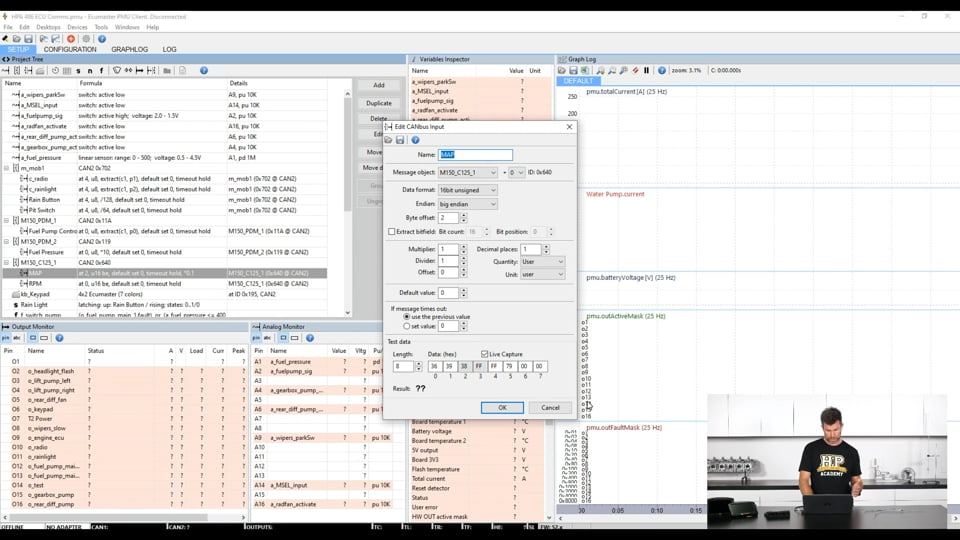
| 49:12 | But let's scroll down here and, oh actually we've got a couple of aspects to deal with our power distribution unit, Ecumaster PMU. |
| 49:24 | So this is actually a receive template from the, or a receive message that the dash is receiving from the Ecumaster power management unit. |
| 49:36 | So this allows us to monitor and log aspects such as our current, voltage and load for each of the channels. |
| 49:44 | So we've got a fairly limited supply of these coming through, we've got the electric water pump current for our radio circuit, our rain light current, fuel pump current, gearbox pump current and diff pump current. |
| 49:55 | So if you're wondering how to set this up, again this is all in the information available from the Ecumaster instruction manual, it gives you the message template, from there it's just a case of copying that and applying it into the MoTeC format. |
| 50:11 | So if we double click on this, the key element here is having the base address correct and then our receive channels, our electric water pump current for example that I've got selected there, if we click on change we can see that in this case, we do have a little bit of work to do with our multiplier and deviser to make sure that they are reading the same so again this is just a sanity check. |
| 50:37 | Once we've got this set up, we want to make sure that the current that the PMU software is displaying for that particular channel is the same as what we're seeing inside the dash, otherwise obviously it's a little bit meaningless. |
| 50:52 | So that's the transmit between the power management unit and the dash itself however we've got a little bit more to do because obviously the ECU is going to be requesting aspects such as our fuel pumps to turn on and off, maybe our thermofans to turn on and off and conventionally we would need to wire these from an output to either a relay or a input on our power management unit to make that happen. |
| 51:19 | So we can do this via a CAN message instead. |
| 51:22 | Now this is where it gets a little bit tricky with our inter product communication. |
| 51:27 | If we are dealing with MoTeC PDMs then this all becomes really easy but if we come back to communications, if we click here on ECU, oh actually no we don't want to do receive, we want to come back to our ECU transmit and if we click on ECU transmit this will actually give us a little bit of information, a bit of a help file on what is being sent out on this. |
| 51:53 | As I mentioned, we don't have control over it, it's basically sending a pre determined array of data but part of this here, and I'm not going to get too deep into it but this information here is going to be useful for our PDM. |
| 52:10 | In particular we can decode some of this information, we can also send some data some requests straight to the PDM. |
| 52:18 | So it's basically a case of taking that information and then programming that into our Ecumaster PMU so that it can receive all of that information so let's have a look at what that looks like inside of our PMU. |
| 52:32 | So the part we're interested in here is our setup, we're over here on the left hand side. |
| 52:36 | So for a start, we've got a CAN message coming in on CAN 2 on a hexadecimal address 702 and this is actually coming straight from the Ecumaster CAN switchpad. |
| 52:49 | So again just showing the power of the CAN bus. |
| 52:53 | So we've got this Ecumaster switchpad, it's communicating directly to our MoTeC C125 dash, it's also sending that same information on a CAN bus where it can be received straight into the power management unit as well. |
| 53:07 | So particularly there we've got an input for radio. |
| 53:10 | So this basically enables our radio for communication back to the pit. |
| 53:16 | We've got our switch to turn on our rain light. |
| 53:19 | So that'll flash the rain light on the back of the car. |
| 53:22 | We've got a rain button and we've got a pit switch. |
| 53:26 | Then we've got our M150 PDM 1 receive. |
| 53:30 | So this is information here that is again in that predetermined transmit template from the MoTeC ECU. |
| 53:38 | All that is is a case there of defining the correct CAN bus, which we've got here, CAN 2 as well as the base address which is in this case 011. |
| 53:50 | We can actually interestingly the Ecumaster PMU is really powerful in this regard because it kind of gives us a little built in CAN bus sniffer. |
| 53:59 | So if we are trying to set this up, we can basically function the output and we can physically make sure that we are actually receiving the data that we think we are. |
| 54:09 | And that's going to be really helpful as well for scaling some of the inputs that we are bringing in. |
| 54:14 | So basically once we've got this, this is a fuel pump request and that will then allow us to use that fuel pump request from the ECU to turn the fuel pumps on and off with absolutely no wiring other than our CAN bus which is already existing. |
| 54:29 | We've also got another PDM function here which is fuel pressure. |
| 54:34 | So we've got fuel pressure coming in, that's on CAN bus 2, again we'll just double click on this. |
| 54:41 | CAN bus 2 there on the address 0119 and again we've got the little CAN bus sniffer to allow us to see what's going on. |
| 54:49 | Some other information that we've got coming in from the MoTeC C125 dash.. |
| 54:54 | This is again on CAN bus 2 we've got a manifold absolute pressure and our RPM. |
| 55:00 | So if we double click on one of these parameters we can then go through, we've got basically the same parameters that we've already seen. |
| 55:06 | We can set the multiplier and deviser, we've got the ability to set the byte offset, where abouts in the message we are going to find that and again we've got the live capture down here, obviously we're not live with the ECU at the moment so we can make sure that the, in this case manifold absolute pressure that we're receiving into the PMU does match what we do have on the ECU or the dash. |
| 55:33 | We'll also be able to monitor all of those parameters live. |
| 55:36 | So we've got here, yep those ones will do. |
| 55:41 | We've got our fuel pump control request, our fuel pressure, our manifold pressure, our engine RPM, rain button and our pit switch just to name a few. |
| 55:50 | So we can just make sure that all of those parameters are coming through. |
| 55:53 | So I know it does seem a little bit complex but if we break it down and we understand we're just transmitting data on a specific address in a specific format. |
| 56:02 | We want to receive that data and make sure we're looking for it in the same place on the same message. |
| 56:07 | It does become relatively straightforward. |
| 56:10 | We are going to get into some questions really shortly so what I want to do is if you've got questions this is the time to ask them. |
| 56:18 | What I want to do now is just go through some of the more specific communications we've got going on with this car because it is a relatively complex case study in getting this data in. |
| 56:29 | So we'll head back to our dash and what I wanted to do is just come through and talk about our lambda inputs. |
| 56:37 | So we're getting lambda in a couple of different ways here. |
| 56:40 | So the first one is nice and easy, this is a MoTeC LTC or lambda to CAN. |
| 56:46 | Now this is designed to work with both the M150 ECU and the dash so it's simply a case of wiring it up with our CAN high, CAN low power and earth, choosing LTC number one which is on a base address, hexadecimal 460 and that is going to straight away give us all of this information over here on the right hand side. |
| 57:05 | The main one we're obviously interested in is lambda 1, the actual air/fuel ratio. |
| 57:10 | But there's a lot of other information in there as well, pump current temperatures, diagnostic information as well which is important because it allows the dash, the ECU to know if the lambda value can be trusted or the system is in fault. |
| 57:24 | Now in our particular application I wanted to go a little bit deeper than this and analyse the individual cylinder lambda. |
| 57:32 | So let me scroll down here. |
| 57:36 | For simplicity because I already had them, I had 4 Link CAN to lambda units. |
| 57:42 | So we've got receive templates from these as well as a transmit. |
| 57:47 | So let's just have a quick look at this. |
| 57:49 | We'll look at CAN lambda for cylinder 1. |
| 57:52 | So double click on this. |
| 57:54 | So we are receiving the information of course and it's coming straight from that Link CAN lambda. |
| 57:59 | We've got the base address which Link will define for us and we are using fast receive, the devices transmit rate. |
| 58:07 | And then we've got our receive channels here. |
| 58:09 | This is a compound message as well so we have 2 identifiers here. |
| 58:12 | 3200 and 3300 and then the actual channel, so in that first identifier, we're getting our cylinder 1 lambda error, we've got lambda cylinder 1, temperature of the controller as well as, temperature of the heater I should say, as well as status. |
| 58:30 | If we click on the second identifier that's giving us the pump voltage and the heater voltage. |
| 58:36 | Alright so where do we get this information, how do we actually make this receive template? So what we'll do is we'll just head over to the Link CAN lambda instructions. |
| 58:47 | So this is straight off Link's website, I've already scrolled down to the part that we're interested in here. |
| 58:54 | So what we've got is first of all, gives us the identifier for the particular unit. |
| 59:00 | So in this case the identifier is displayed here, first of all 950 and then beside this in brackets 0x3b6 which is the hexadecimal and the decimal variants for that same unit. |
| 59:15 | Let me just enlarge that a little bit. |
| 59:19 | Make sure I actually can read that properly. |
| 59:21 | Alright so then we've got the 2 identifiers there, information being sent through. |
| 59:26 | So first of all, we've got our error code on our first byte. |
| 59:30 | Then we've got lambda being sent across in 2 bytes of information, data 2 and data 3. |
| 59:37 | Then we've got our sensor temperature, again being sent through in 2 bytes of information. |
| 59:43 | And then we've got our status. |
| 59:46 | We can see that we've got flags telling us what the status is here in terms of what's going on, whether it's off, disabled, initialising etc. |
| 59:54 | There is also information about the scaling so this really comes back to what I was talking about, making sure the scaling is correct. |
| 01:00:00 | So in this case the lambda value is multiplied by 1000. |
| 01:00:04 | So a value of 1.000 lambda is represented as 1000 so the raw value for our lambda is multiplied by 1000 as the device transmits it and then of course we would need to divide by 1000 to get the decimal point back in the correct place. |
| 01:00:19 | Likewise we've got our data being sent here for our temperature, pretty straightforward, 780 is 780 so no need for a multiplier in there. |
| 01:00:29 | Then on the other identifier we've got our pump current being sent through. |
| 01:00:34 | Again the scaling information that we need there, multiplied by 1000 mA. |
| 01:00:38 | We've got our battery voltage, in this case multiplied by 100 again just to get that decimal point correct. |
| 01:00:44 | And we've got our heater voltage. |
| 01:00:46 | So that's where we get all of that information. |
| 01:00:48 | We don't need to make it up ourselves, we don't need to guess. |
| 01:00:51 | So if we come back up to our first identifier here and on our lambda cylinder 1, click on change. |
| 01:01:00 | We can see basically we're matching that. |
| 01:01:02 | Where abouts in that message we're finding the data, the offset of 2. |
| 01:01:05 | The length of that data, you'll remember it was 2 bytes of information. |
| 01:01:08 | Now interestingly here, you can see that I don't actually have a multiplier and a deviser, this is because the base resolution that MoTeC is expecting this data to come through in is exactly the same, in this case 3 decimal places. |
| 01:01:23 | If that wasn't the case, we would need to mess around with a deviser but in this case it's nice and easy. |
| 01:01:29 | So you're not always going to get this right the first time and it's not a problem, it's just about doing that sanity check, making sure that the data that we are receiving matches the data that we are showing. |
| 01:01:40 | So otherwise you can end up getting yourself in a bit of a jam. |
| 01:01:44 | Alright so that's our input there and basically it's a rinse and repeat for all of those different parameters. |
| 01:01:50 | We can then make sure that we are actually seeing the data that we are expecting, once everything's online. |
| 01:01:56 | However goes a little bit further here, the Link CAN lambda also gives the ability to compensate for exhaust manifold back pressure and we can also control the actuation or the operation of the lambda controller via an RPM signal. |
| 01:02:13 | So if we send that information out to the CAN lambda unit, that's also going to be helpful. |
| 01:02:18 | So that's where the next piece of the instruction manual comes in, our received information. |
| 01:02:21 | In this case the CAN lambda is the unit doing the receiving. |
| 01:02:26 | So if we send out information on this base address here, 958 decimal, we will see that we can send out on data bytes 2 and 3, our engine speed. |
| 01:02:40 | So our engine RPM being sent out across 2 bytes as we'd expect and then bytes 4 and 5. |
| 01:02:46 | If we send out our exhaust manifold back pressure if we have that available then the unit will be able to compensate for exhaust back pressure. |
| 01:02:56 | We've got data byte 6 as well, this is defined whether or not it will use exhaust back pressure compensation. |
| 01:03:03 | So handy to do this if we can and we can so let's have a look at how we did that. |
| 01:03:08 | We come down here to our Link CAN lambda transmit. |
| 01:03:12 | And what we've got here, in this case I'm sending out constants, not quite sure why I did this, this is probably for a test. |
| 01:03:21 | But basically we're sending out constants to replicate a constant engine RPM. |
| 01:03:26 | But let's have a look at the key one that we're really interested in here is our exhaust manifold pressure. |
| 01:03:32 | So we can see that we've got our offset and our length matching the data. |
| 01:03:36 | In this case again it's just a case of confirming our base resolution as to whether or not we need to use a multiplier and a deviser. |
| 01:03:44 | In this case of course the format that the MoTeC is sending the information in matches what the Link unit is receiving in so we don't need to do anything there. |
| 01:03:54 | That will get that information through. |
| 01:03:55 | GP constant 5, this is the other piece of information that defines whether or not the unit will use the back pressure compensation so we're just telling it here, yes we want to use back pressure compensation. |
| 01:04:08 | So that's a nice neat way of getting individual cylinder lambda from a competing product into a MoTeC dash. |
| 01:04:16 | Interestingly in one of our other test cars, I actually also sent that information back into the MoTeC M150. |
| 01:04:24 | To do that I kind of cheated a little bit. |
| 01:04:25 | Basically I replicated the format of information from a MoTeC lambda to CAN unit and I just transplanted the actual lambda value from the Link CAN lambda units and sent that back into the MoTeC M150 which worked really well. |
| 01:04:40 | The only trick with that to watch is the way I did that, it meant that we didn't actually have diagnostic data coming through from the Link unit. |
| 01:04:50 | Alright we're running a little bit long here but I do want to just mention another couple of aspects here. |
| 01:04:56 | So the next one is our Haltech TCA8, so Haltech thermocouple amplifier 8. |
| 01:05:04 | In this case we're only using 4 of those available channels so not too hard to figure out why with a 4 cylinder engine. |
| 01:05:11 | But if we double click on this, we can see the address here, again this comes from Haltech's information so we don't need to guess, we'll know what address the information is being transmitted on, we've got our receive channels here, these are sent as a single message so no compound messaging, nice and easy here. |
| 01:05:30 | If we click on change, we can see that in this case we do need a adder, or actually a subtracter in order to get our EGT data reading but pretty self explanatory, pretty straightforward to get that EGT data into there. |
| 01:05:46 | The last one I'll talk about here is our Izze Racing tyre temperature and pressure monitoring system. |
| 01:05:51 | So this as you can see here, quite a large range of data being transmitted here from our Izze Racing units and again we don't have to guess about this. |
| 01:06:03 | Izze actually make it really nice and easy for us because for I think MoTeC as well as AiM they actually provide a template so it's as simple as loading that template up and all the information will be available. |
| 01:06:17 | However if you want to get a little bit trickier, in the information, the manual on the units, we've got all of the data that we need, we can see for example we've got our bit rate here so 1 Mb per second, as I mentioned, pretty typical. |
| 01:06:31 | We've got our CAN ID. |
| 01:06:33 | So we've got that being displayed in both decimal and hexadecimal. |
| 01:06:37 | And then you can see the message structure so how the information is being sent out. |
| 01:06:43 | Again it's just a case of replicating this as a receive template and you'll be good to go. |
| 01:06:49 | Understandably when there is a lot of information being sent and obviously we have multiple units on the car as well, there is a fair bit of work to do which is why Izze has been really nice in making this all available as a pre determined template that you simply download. |
| 01:07:05 | Alright I think we've probably gone long enough now, hopefully haven't confused you too much but let's jump into our questions and we'll see if we do have any questions. |
| 01:07:25 | Just one for the moment from cmelle who's asked, curious about the dyno CAN sniffer, does the dyno connect to the CAN via the OBD2 plug, can most dyno's do this? It doesn't actually connect to the OBD2 plug in our case, we've got a Haltech Elite ECU on that particular vehicle so I've actually got a specific 4 pin DTM connector for communication between the car and our dyno. |
| 01:07:52 | To the best of my knowledge, the Mainline dyno is still the only dyno that provides this kind of CAN bus interface. |
| 01:08:01 | It certainly did when we go it, it was one of the big drivers behind us getting it. |
| 01:08:05 | Might be a few more that have come to the party now but very very powerful way of getting that information in. |
| 01:08:14 | Aconis has asked, when we want to add some OE data from CAN to an aftermarket ECU, where would we get these details? That one is a little bit trickier, so this requires a little bit of reverse engineering. |
| 01:08:26 | And it's not actually as scary as it sounds. |
| 01:08:29 | To break it down, basically in a nutshell what we're going to do is connect to the existing factory CAN bus, we're going to look at all of the messages on that CAN bus and the tricky part is we want to try and find where abouts in all of that information the message that we're interested in actually exists. |
| 01:08:46 | And that can be tricky because while we're watching all of this it's kind of a bit like the matrix, we've got these numbers constantly changing. |
| 01:08:53 | And the idea is what we want to do is basically force a change to the parameter that we're interested in. |
| 01:08:59 | Let's say wheel speed for example, we're looking for wheel speed. |
| 01:09:02 | Well obviously the way of doing this would be to actually make the wheels turn. |
| 01:09:07 | So we do this and we can watch what parameters are changing. |
| 01:09:10 | The tricky part though there is of course when we want to make the wheels turn, we're going to need to increase the engine RPM and our throttle position. |
| 01:09:19 | So we're going to have multiple pieces of data changing on the CAN bus while we're doing this. |
| 01:09:25 | Nice function with a lot of the CAN bus sniffers is that when a parameter changes, it will be highlighted red so visually at a glance you're going to get an idea of which messages are changing at any time and if we just jump back to my laptop screen for a moment, while this is obviously a picture, and it's static, we can see the little red squares around parameters that have been chainging there. |
| 01:09:46 | So what we can do is basically make a change to the channel that we're interested in, good way of doing this, if you're trying to maybe find engine coolant temperature. |
| 01:09:56 | We can power the ECU up and unplug the engine coolant temperature sensor and then plug it back in and that should be really easy because then we're only looking for one piece of data. |
| 01:10:06 | Likewise manifold absolute pressure, unplug the sensor. |
| 01:10:08 | So that'll get us into where abouts the message is, we'll be able to narrow it down to the identifier but then what we need to do is actually find, well the identifier and the bytes that contain that information. |
| 01:10:20 | What we then need to is actually narrow that down a little further and get the scaling information. |
| 01:10:27 | And to do this really what we need is a scan tool that allows us to read what the actual value is, so for wheel speed for example, we'd run the car on the dyno and we'd hold it at a constant speed and the scan tool would be saying 40 km/h for example, then we'd look at our raw piece of data that we are getting out of our CAN sniffer and we'd apply scaling until that also reads 40 km/h. |
| 01:10:52 | So it's a little bit more to if, if you are interested, there is the other webinar that actually goes through some of that reverse engineering on a very basic level. |
| 01:11:02 | If you search for CAN bus in our webinar archive, you'll be able to find that. |
| 01:11:13 | Ripsen has asked, is there a database of decoded OE common messages and parameter IDs? No it's never that easy, if it was that would be great but unfortunately you need to normally do the hard yards yourself. |
| 01:11:31 | That's not entirely true, with OBD2 onboard diagnostics we do, all the manufacturers have to provide certain information for diagnostics purposes so the key parameters we want there such as engine coolant temperature, RPM, throttle position will be on the OBD2 protocol but often they are transmitted at a relatively low rate. |
| 01:11:54 | So yeah that can be problematic but if we want to get a little bit more in depth, generally we actually have to do some work and actually reverse engineer that ourselves. |
| 01:12:06 | Right I'll leave it at that for today, looks like all of our questions so thanks to everyone who has joined us. |
| 01:12:13 | I'm sure there will be more questions that crop up after this webinar makes it into the archive so please feel free to ask your questions in the forum and I'll be happy to answer them there. |
| 01:12:24 | Thanks for joining us and hopefully we can see you again next time. |
Timestamps
0:00 - Intro
1:15 - What is CAN?
4:15 - Why use CAN?
13:05 - Basics of a CAN message
18:00 - Bus speeds need to match
20:05 - Check CAN bus wires are around the right way
21:30 - Physical CAN bus structure
25:55 - ECU transmit setup
28:20 - Dash receive seup
41:20 - Check your work and any offsets
44:45 - Dash transmit setup
46:40 - ECU receive setup
49:05 - PDM CAN setup
56:30 - Lambda inputs
1:04:55 - Haltech TCA8
1:05:45 - Izze Racing TPMS
1:07:25 - Questions


