294 | Optimising Switched Cam Control
Summary
Switched cam control such as Honda’s VTEC or Nissan’s VVL and VTC systems can provide a wider power band than conventional fixed cam engines. While this style of cam control is not overly complex, there are still some considerations around how this should be configured and tuned. For this webinar we’ll be using our SR86 fitted with a Nissan SR20VE Turbo engine and controlled by a MoTeC M150 ECU.
| 00:00 | - Hey team, Andre from High Performance Academy, welcome along to another one of our lessons and today we're going to be diving into the tuning options when it comes to a switched cam control system and these are reasonably common, although these days have probably been more superseded by continuously variable cam control systems but they actually give some advantages and there are some differences between switched cam control and continuously variable cam control. |
| 00:27 | So before we get too far into it, we need to understand what this technology is. |
| 00:31 | It's available from a range of different manufacturers and they all have their own slight differences in the way they do this. |
| 00:40 | Probably the most common or most popular or well known switched cam control system is the Honda VTEC system. |
| 00:47 | And this is also very very similar to the technology that Nissan used in their SR20VVL cylinder head. |
| 00:57 | So that basically consists of a camshaft like we've got here which has 3 profiles on it. |
| 01:03 | So we've got what's called a low speed cam profile which is these two outer cam lobes. |
| 01:09 | And then we've got the middle cam profile which is our high speed cam. |
| 01:13 | So this again is exactly the same as how Honda do it with their VTEC system and what it does is allows us to have two completely different cam profiles optimised for different operating conditions for the engine. |
| 01:27 | This is one of the problems for us in the aftermarket when it comes to selecting a cam profile for an engine. |
| 01:33 | If we want to get really good high RPM performance and good cylinder filling, good volumetric efficiency at high RPM which is going to give us high levels of power and torque, what that's going to require is a lot of lift and a lot of overlap. |
| 01:49 | On the other hand if we use that same aggressive cam profile that worked so well at 7000, 8000, 9000 RPM, if we use that at low RPM, our idle quality is going to be absolutely garbage, the fuel economy's going to be terrible and so is our drivability. |
| 02:05 | From an OE standpoint it's also going to absolutely destroy the vehicle's emissions. |
| 02:10 | So that VTEC style multi lobe cam gives us the best of both worlds. |
| 02:16 | Basically we can have a small cam profile that's going to give really nice idle quality, it's going to give good fuel economy at cruise and it's going to give good drivability, good low RPM power and torque. |
| 02:27 | However if we use that cam profile at high RPM, basically the airflow, the volumetric efficiency through the engine's just going to end up falling off a cliff as the RPM climbs. |
| 02:37 | So we switch that high cam profile, that large lobe cam profile that gives more lift and more duration and more overlap, and that's going to be optimised for high RPM performance. |
| 02:48 | So again basically the best of both worlds. |
| 02:52 | I'll just quickly jump to our overhead camera here. |
| 02:55 | This is probably no big surprise to anyone who has been involved in engines for any period of time but this is the inside workings of a Honda B18C cylinder head. |
| 03:07 | I have the cam out of it here and basically we have these 3 little rockers that the cam lobes run on. |
| 03:14 | So we've got these two outer cam lobes. |
| 03:16 | These actuate directly onto the tips of the valve, and here we've got our little adjustment here so we can adjust our valve lash. |
| 03:23 | This middle rocker here as you can see is at the moment it is unlocked, it's not doing anything so at the moment the cam, the valves will be actuated just by those smaller outer lobes. |
| 03:36 | So this is in the low VTEC or low speed operation mode. |
| 03:39 | However it's really hard to see in here but you'll have to take my word for it. |
| 03:44 | Basically we've got a little plunger system inside these rockers, this is high pressure oil actuated so it's actuated by the engine oil and when the VTEC solenoid kicks in, basically what it does is it provides high pressure oil to this rocker assembly, pushes out the little plunger in there and it locks all 3 lobes together. |
| 04:07 | Now when those are all locked together the cam as it swipes past, that larger cam lobe in the centre, that's going to actuate on that middle rocker and it's going to move the valves together so that's essentially the basis of the VTEC system in terms of its mechanical capability. |
| 04:25 | You don't need to know about this in order to be able to tune the system but I just wanted to give you a better understanding of it if you didn't know how it works. |
| 04:33 | So that covers VTEC and Nissan's VVL. |
| 04:36 | There are a few other strategies in the market there that OEs have used over the years which actually don't involve changing the physical cam lobe. |
| 04:47 | The other way of doing this is a switched cam timing system. |
| 04:51 | So Toyota did this with their Black Top 4AGE and Silver Top 4AGE. |
| 04:58 | It basically had a switched cam position for the intake cam and it retarded and advanced the cam based on engine RPM. |
| 05:07 | This is very similar to the current crop of continuously variable cam control systems but it wasn't continuously variable, it was just either fully advanced or fully retarded, again oil pressure controlled so it's sort of a precursor to modern continuously variable cam control systems. |
| 05:24 | Nissan also had the exact same strategy on some of their engines, some of the SR20s with their VTC system and also some of the RBs as well and that was again just a switched cam advance or retard. |
| 05:38 | Regardless which system you're dealing with though, the tuning strategy is essentially the same so it doesn't really matter, just understanding what you've got there is quite important. |
| 05:49 | There are also some hybrid systems, Honda went a little bit deeper with their K series engine, they employed both VTEC switched lobe strategy which we've just looked at, along with a continuously variable cam control on the intake so that allows us to have low speed cam profiles, high speed cam profiles and then the whole way through the rev range in low range, the intake cam timing can also be altered so that just adds another layer of complexity to the tuning. |
| 06:20 | We're not going to focus on the iVTEC system. |
| 06:23 | Really if you understand what we're going to cover today, tuning switched cam control systems, we've also got our variable cam control tuning course which covers what we're talking about today as well as continuously variable cam control. |
| 06:36 | Basically if you understand both of those technologies, they're not that difficult to then go ahead and tune an iVTEC system with both technologies in one. |
| 06:47 | Alright so that really covers the what and the why of switched cam control. |
| 06:52 | What we also need to understand is how we can actually control this from a software standpoint. |
| 06:59 | And this is really where there are a few variations depending on what we're trying to do, how deep we want to get into the control and how thorough we want to be. |
| 07:11 | Basically to break this down, 99.9% of tuners are going to simply have a single table for fuel and a single table for ignition. |
| 07:21 | They're going to configure an output to switch the cam, be that an advance or retard system or a VTEC style system at a certain RPM switch point. |
| 07:33 | And then that's all they're going to do. |
| 07:36 | If you want to get a little bit deeper into it though, the cam switching point which we'll deal with in a bit more detail shortly will vary depending on the load the engine is operating at. |
| 07:46 | What I mean by this is that if we're at wide open throttle, maybe our VTEC switchover point or our cam switching point might want to be 4500 RPM, if on the other hand we are at light throttle and we're only at maybe 50 kPa vacuum, we may find that the cam switchover point actually wants to be quite a bit higher. |
| 08:06 | Maybe 5000, 5500 RPM. |
| 08:09 | So we can have this system called windowing. |
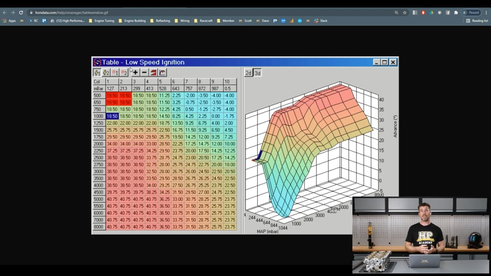
| 08:12 | That adds a little bit more complexity into our tuning strategy so to start with, let's just have a look at how this is dealt with in an OE setup and it's unfortunate, I did expect to have this downloaded but I've got an update that is pending here for our Hondata S Manager so you'll have to bear with me. |
| 08:34 | If we come into our parameters here, the part that I wanted to show you is how Hondata deal with the VTEC changeover. |
| 08:41 | So we'll go to the VTEC tab under parameters and what we can see is we've got this set up here, just try and do this a little bit nicer. |
| 08:49 | Which is called VTEC window. |
| 08:54 | So unfortunately I can't show you a base calibration here with numbers but basically what this allows us to do is have a boundary so depending on our vacuum, so what we've got in here is a lower boundary and we've got the RPM that the VTEC switchover will occur at and we can then set the manifold vacuum in this case in inches but we can also set it in kPa and millibars, that switchover will occur. |
| 09:18 | So that gives us one switchover point. |
| 09:20 | Then alternatively we've got our upper boundary and we can have a different switchover point. |
| 09:25 | So basically depending on the manifold vacuum which is obviously driven by our throttle position, this is where we can switch the VTEC changeover point at different RPM based on whether we're at wide open throttle or whether we're at part throttle. |
| 09:39 | So if we optimise this correctly, like Honda attempt to do, what this will mean is that compared to a single switchover point in RPM we're going to actually give ourselves a little bit of a boost in part throttle power and torque where normally we would have switched at low manifold pressure too early for the timing to be optimal. |
| 10:03 | So that's how Honda do it but this does bring in a bit of complexity because that is difficult to do properly if we are only dealing with a single fuel and ignition table. |
| 10:14 | I'll just go back to my pictures here, so this is how Honda deal with this. |
| 10:20 | Again unfortunately I can't show you through this in the S Manager software. |
| 10:24 | But what they have here is two sets of tables. |
| 10:28 | So we've got a little spark icon and we've got 1 and 2 and then we've got a little spray icon or fuel injection icon and 1 and 2. |
| 10:38 | So basically what Honda do in the OE strategy which Hondata just give us access to so we can make alterations, is they have a complete table for low speed operation, when we're on the low speed cam profile and then when we switch to the high cam profile, the high RPM cam profile, they switch to the high speed fuel and ignition tables. |
| 11:00 | So which of these tables we're on is driven by whether we're on the high lobe or the low lobe of the VTEC system and that's driven by that windowed system that I just showed you so it's quite nice because if both the high speed and low speed fuel and ignition tables have been optimised, essentially what that means is irrespective of where the VTEC changeover point occurs, we know that the fuel and ignition is going to be correct. |
| 11:27 | And Honda also utilise this in another way because the VTEC system won't actually function if you're just sitting there stationary at a set of lights and you rev the engine to 7000, 8000 RPM. |
| 11:39 | It's not actually going to switch to high VTEC, high cam and it's going to stay on that low cam profile, it'll stay on the low cam fuel and ignition tables and everything's optimised. |
| 11:48 | So that's just how Honda do it, doesn't mean it's the only way but I just wanted to show you how that strategy is employed by them. |
| 11:58 | We can do this in the aftermarket, it just does require a little bit more work. |
| 12:03 | Now as I said, most people are going to do this in a single table and I just want to show you what that might look like. |
| 12:12 | So originally we were intending to do this particular webinar on the dyno with our SR20, unfortunately due to some work that is progressing on that car, we can't do that at the moment so we may revisit this but I can still talk through exactly what's going on here. |
| 12:30 | So this is the M150 system, I'm going to show another couple of options in a moment as well if you aren't using the M1. |
| 12:38 | But here we have our fuel worksheet which is what we're looking at now and this is our volumetric efficiency table so we've got that demonstrated over here in a numeric format and then graphically over on the right hand side. |
| 12:52 | Now with this particular system, oops I don't want to do that, with this particular system, what we can see, if we look at the VE table is for the most part it's got a relatively normal shape to it. |
| 13:06 | Except we've got this weird step here. |
| 13:10 | And if we cycle around the other way we can sort of see we've got the opposite step up here so just in case you aren't aware, basically how this VE table works is somewhere around about here this is 100 kPa, so this side of that line that I just sort of drew in there, this is the on boost area, the high boost are and then down below this is our vacuum area. |
| 13:34 | So this is just really showing that this engine actually wants a windowed system that's going to be optimal. |
| 13:41 | The reason being is that in the on boost area which is obviously where we're optimising under wide open throttle, we've got this little step in the volumetric efficiency which is pretty typical. |
| 13:51 | Generally with our VTEC or cam switching optimised nicely we're going to see little to no real step as we cycle through that point at wide open throttle. |
| 14:04 | However again if we come down here we can see that our volumetric efficiency actually drops away significantly as our RPM goes up. |
| 14:12 | So let's have a look at those numerically and in this instance our switchover point is 4600, I'll talk about that in a little bit more detail. |
| 14:21 | So we can see at high load, let's see we're running through at about 200 kPa which is this area through here. |
| 14:30 | And on the low cam side of that we've got a VE number of 126.2 and then on the high side of that, 126.3 and then we step up to 130 so actually over the VTEC changeover point, almost no difference, very slight step beyond that. |
| 14:52 | However at lower load if we were down at 60 kPa for example we can see that either side of that VTEC changeover point we've got a value of 89% volumetric efficiency dropping all the way to 47. |
| 15:06 | So if we actually follow that through, not that these are probably that optimised, yeah we don't actually have a number of 87 but basically what this is doing is just showing that the cam switching point at low RPM wants to probably be more out about maybe 6000 RPM than down at 4600 so what we would end up with if we could optimise this at each load point, we'd probably end up with our cam switching point looking something like this. |
| 15:34 | And then as our load comes down we're probably end up wanting to have our cam switching window do something like that. |
| 15:44 | This is a race engine, it's not driven to the shops and I don't really care too much about the optimal performance down at 4600 to 5000 RPM at part throttle. |
| 15:57 | Essentially we're almost never there. |
| 15:59 | If we are there, we're completely off throttle so it doesn't really matter in our instance, even though isn't optimal and we're in a situation where if we are in that area and we need more power and torque, simply opening the throttle is going to get us this but I just wanted to explain this, this is why Honda have that windowed strategy and that would be the way of optimising this which for a road car definitely is something that I would recommend, it's something that 99% of tuners are never going to do, most tuners don't even know that that windowed requirements exists and how to deal with it. |
| 16:34 | There are a couple of problems though with the MoTeC M1 system, we are relatively locked down here with the way the M1 strategy works so we really are only working off a single efficiency table so we can't do that dual table like we would see in the Honda OE strategy so we can't really deal with this the way Honda do which is another reason I've left that the way it is. |
| 16:58 | While we are looking at the M1 though, let's look at a couple of the control options. |
| 17:03 | So if we come into our tuning and I think initial setup 2 is where we'll find it, we're going to come across to our cam control inlet worksheet here. |
| 17:14 | And this is actually more usually the worksheet that you would use for a continuously variable cam control system where we're mapping the cam target and making sure that the PID control algorithm for the cam control is working. |
| 17:29 | However for switched cam control systems they do also have switched camshaft which is down here. |
| 17:35 | What I'll do is we'll just full screen that particular option and see what our options are. |
| 17:40 | So let's have a look through each of them. |
| 17:42 | For a start we have our inlet cam actuator resource. |
| 17:45 | So pretty straightforward, that's just what output on the ECU is actually going to control the solenoid for our cam switching. |
| 17:52 | I will just mention as well the Nissan SR20, there's two variants of the VE cylinder head or VVL cylinder head. |
| 18:02 | There's the P11 and the P12. |
| 18:03 | The P11 actually had individual solenoids for the cam switching for the intake and the exhaust, the P12 reverted to a single. |
| 18:12 | Generally the advantages of the dual solenoid system really relatively insignificant and because of the location of the solenoids which end up on the back of the cylinder head in a north/south application like ours, it's pretty common to go to the P12 strategy with a single solenoid, it just removes the bulk off the back of the cylinder head so just for those who maybe are familiar with the VVL cylinder heads, that's why we are only running a single solenoid that will switch both cams at the same time, very similar again to Honda's strategy. |
| 18:44 | Alright so, let's have a look at the actual switching. |
| 18:48 | So we've got two switch points, we've got inlet cam position threshold high and low. |
| 18:53 | So in our case we only want to switch the cam on as we run through the rev range. |
| 18:59 | That's not always going to be the way, particularly with some of the Nissan VTC systems where we're talking about advancing and retarding the cam as opposed to switching lobes. |
| 19:09 | It's quite common to turn that system on at low RPM and then turn it off again at high RPM so that basically gives us a window to allow us to do that. |
| 19:18 | In this case you can see I've got it set up, the low threshold at 4600 so it's turning on at 4600. |
| 19:24 | I've set the high threshold here at 10,000, we're never getting there, we're not revving to 10 but basically if we did, at 10,000 RPM it would switch the cam control back off. |
| 19:34 | So we'd go back to our small lobe cam. |
| 19:36 | So basically I've just moved that out of the actual usable rev range of the engine. |
| 19:41 | If it was a Nissan, maybe we wanted to turn it on at let's say 1500 RPM and we may want to turn it off again at 6000, we would just choose numbers that are suitable. |
| 19:50 | A really important aspect that again is so often overlooked here is this parameter here called inlet camshaft position hysteresis. |
| 20:00 | It's a bit of a mouthful and again I know this is little understood so hysteresis simply means that the switch on point is going to be different to the switch off point. |
| 20:11 | So let's take our example for a moment here. |
| 20:14 | 4600 is where it switches on. |
| 20:16 | If we were to sit at steady state throttle at just on 4600 RPM, what we can get into a situation is where the cam control is shutting on and off at very high frequency which is not going to be nice for the engine, it's not going to feel nice to the driver. |
| 20:36 | So with this system what that means is that once we pass through 4600 RPM, the RPM's actually going to have to drop by 150 RPM in order to deactivate the system. |
| 20:46 | 150, probably actually a little bit more than I'd normally use, normally about 50 RPM is sufficient so just to basically stop it shuttling on and off. |
| 20:57 | I have had first hand experience with this because the original firmware package that we were running on our SR20 when we got it up and running did not offer an actual physical switched cam control output like I'm looking at here so we're just using an auxiliary output to switch at a given RPM and that auxiliary output did not give us the hysteresis option. |
| 21:22 | It was horrible to drive on the track if we were around that VTEC changeover point and even on the dyno what we would see because it's so sensitive is as the RPM exceeded that cam switching point, it would switch and often that would, not every run on the dyno but often that would actually result in the RPM dropping very momentarily and it would switch off before switching back on again and you'd sort of end up with a funny blip in the torque curve so but of hysteresis in the system is very very important. |
| 21:53 | As I've said, 150 probably a little bit excessive, 50 should be enough to get the job done there. |
| 21:58 | So that's how we've got the setup done in our SR20 with our MoTeC M1. |
| 22:06 | Let's go back to our tuning and we'll have a look at our VE table again. |
| 22:10 | So what we do need to understand with the VE table is if we just, oops no I don't want to do that. |
| 22:20 | I want to do that, if we just cycle this around again, we can see that as I've mentioned, as we move through the switched cam point at high load, not really a big jump in our volumetric efficiency, if there was a really massive jump, that would actually be a bit of a red flag that potentially we do have our cam switching point set non optimal so that is something to watch out for. |
| 22:44 | But as we've already talked about, we do have this problem down here. |
| 22:49 | Now this is where our resolution and our break points come into play and this is another aspect you do need to keep in the back of your mind when you're tuning these switched cam systems. |
| 22:59 | Because that light load area, we're getting a very very big change in volumetric efficiency across very very small RPM range. |
| 23:09 | So more normally I would have my break points set like we've got here, you can see 4000 and then 4500. |
| 23:16 | If we go to the other side you can see again pretty typical break points, every 500 RPM, that's normally about all we need. |
| 23:23 | What you can see here though is I have purposefully set up really tight break points right on that VTEC changeover point, we've got 1 point at 4600 and we've got 1 at 4601. |
| 23:35 | Actually probably should be 4599 because it's switching at 4600. |
| 23:41 | So what I'm trying to say here is we're going to have a volumetric efficiency break point just prior to the VTEC changeover point and one just after. |
| 23:48 | Doesn't need to be 1 RPM, 10, 20 RPM but basically something that is a little bit tighter than our normal 500 RPM and the reason that's important is not so much up in this area here because again our VE step is not large but down here where our VE step is really significant. |
| 24:06 | What's going to happen here is let's take these two cells, so let's say we are at 4600 RPM, 60 kPa our VE is 89%. |
| 24:18 | Our next cell that we've tuned here under normal conditions would be 5000 RPM and we've got a value of 50.8. |
| 24:26 | So what would happen normally if we only had 500 RPM break points is that this cell in between which is currently 47.7, that would simply be a linear interpolation so let's just do that as well. |
| 24:39 | Oops we can do, nope not that one. |
| 24:42 | Let's do a linear interpolation here, interpolate. |
| 24:46 | Oh it's not going to do that because I have that set as a point, there we go, that's going to be better. |
| 24:54 | So what you can see here is now 4601 RPM, the volumetric efficiency has interpolated to 88.9%. |
| 25:02 | Massively massively incorrect. |
| 25:05 | So what that's going to end up doing is in that area, the engine's going to be massively overfuelled, I can't quite remember the exact number it was, let's just go back, 47.7, so yeah it's going to have way more fuel in it than it needs, That's probably going to make the engine feel a little bit doughy through that area so that's why it's important if you are going to be using that single switching point for RPM, that is why it's really important just to add a little bit tighter resolution to your break points around that, either side of it so you can deal with that and make sure that you're going to be correct on either side. |
| 25:41 | Now there is another little tip when it comes to tuning this style of system if you have got those really tight break points because right now, you can see, 4600, 4601, if we were sitting around there on the dyno under steady state, we're just going to be moving constantly between the two. |
| 25:59 | So what I tend to do here when I am setting this is if I want to tune the 4600 RPM column of my table, what I'd do momentarily is set my VTEC changeover point well out of the way, let's say 5500, that way I'm not going to be basically switching in and out of VTEC so it's going to allow me to tune the low cam lobe column at 4600 RPM nicely and I'm going to be able to do a good job of that., Conversely when we get to the column at 4601 or wherever we've put that, we're then going to bring out our cam switching point down, we make that maybe 4000 RPM so again we're not going to have any risk of it cycling on and off and that'll allow us to properly tune our 4601 RPM row. |
| 26:47 | When we are doing this, again, 1 RPM definitely not needing to be that tight. |
| 26:52 | Let's say it was 20 RPM differential. |
| 26:55 | What we want to do is just makes sure that when we're on our dyno that our RPM is if anything slightly higher when we're doing our 4601 RPM column, maybe we want to make that 4610 to 50. |
| 27:09 | Reason I'm saying that is we don't want to be interpolating if we're moving backwards and forwards between those two zones because again there's a big difference in the values and the interpolations are really going to have you chasing your tail so basically what I'd want to do, normally we'd want to be central in this zone when we are tuning it, I would want to just make sure that if anything, I'm edging slightly towards that next zone up, I want to definitely make sure that we are never dipping down into that lower zone and that will give us the ability to tune those nice and accurately. |
| 27:42 | Now the next obvious question is how do we know what the cam switching point should be? And again if we're using this single table, we're obviously just focused on our performance under wide open throttle which is what most people care about and it is incredibly easy. |
| 27:59 | This is probably one of the steps I do relatively early in the tuning process so I'm not going to be wasting a huge amount of my time optimising areas of the VE table for the wrong cam mode operation so we'll just head to my photos for a second. |
| 28:15 | So this is our SR20 on the dyno and basically what I will do is start by doing a run out to the rev limiter or at least high in the rev range, it doesn't necessarily have to be the rev limiter because we know that we're going to be switching to high lobe before the rev limiter so let's say we start at 2000 RPM and we run out to maybe 6000 RPM. |
| 28:41 | With the cam switch control completely disabled, we're running purely on the low lobe so that is our blue line that we can see in here. |
| 28:50 | So we can see it's pretty smooth. |
| 28:52 | I have actually run this all the way out there and we go out to about 7500 RPM. |
| 28:57 | The next step is I'm going to then configure the VVL system to turn on relatively low in the RPM and in this case that red line, I am switching this here at I think it's about 3000 RPM, that point there. |
| 29:15 | A lot of people would say well why don't I just switch it on at idle? You do have to be a little bit mindful of this, this is an oil pressure driven system and our oil pressure is related to our engine RPM. |
| 29:26 | So first of all if you try switching a VTEC system or a VVL system on at too low of an RPM, it's probably unlikely to work reliably but more importantly it can actually end up taking oil that you really want lubricating your bearings so a little bit of experience comes in here. |
| 29:45 | I know that it's very unlikely I'm ever going to want to switch a switched lobe style cam control system below probably 3000 RPM. |
| 29:54 | If it turns out that that's what it wants, we'll quickly see that anyway so in this case 3000 RPM, do another ramp run and we can see straight away that at 3000 RPM our power actually drops. |
| 30:08 | So what that means is that our volumetric efficiency is worse than when we were on our low cam lobe. |
| 30:15 | However we can also see that at this point here which is about 4600 RPM, we see the red line jump up above our blue line which was our low cam lobe and basically we've got an advantage all the way out to the rev limiter there. |
| 30:31 | So this gives us a pretty good indication that the point that I've got on the dyno there where the white line is, this is probably there or there abouts where our VTEC changeover or our switched cam changeover point is going to want to be. |
| 30:45 | Couple of caveats to keep in mind. |
| 30:47 | As I mentioned, I generally do this when I'm mapping an engine from scratch, I'll generally do this reasonably early on, I'm not going to go and completely optimise my fuel and ignition tables and spend a huge amount of time before I've got the VTEC at least in the ballpark. |
| 31:06 | The reason for this is we just end up as I mentioned, optimising an area of the map that we're just never going to run in so obviously we need numbers in here that are at least going to let the engine run, we want the ignition timing to be in the ballpark, there or there abouts and in this case I'm leaning quite heavily on the MoTeC M1 closed loop fuel control and what that does is basically add or subtract fuel if the air/fuel ratio isn't exactly where I want it. |
| 31:32 | So it's going to be close by it might not be perfect. |
| 31:35 | So what I want to do is get that VTEC changeover point set close to where it needs to be, optimise my fuel and ignition timing properly at that point and then I'm going to do a little bit of windowing where I will bracket the VTEC changeover point higher and lower and just see if there is any advantage. |
| 31:53 | So process again, I haven't actually got the combined graph that I would have done straight after this but I would have set my VTEC changeover point at 4600 RPM, done another run and essentially what we should get is a situation where the third line basically follows the high points of all of the other two lines. |
| 32:14 | There can be a bit of manipulation in this, there's always a bit of latency in the switchover point so if we see 4600 or in this case it actually has switched slightly later, you can see this point here is 4590 so it's actually probably switched closer to 4700 but with a bit of latency, you might find it needs to switch a little bit earlier for you combined dyno plot to actually follow the highs of both of those lines. |
| 32:40 | So let's have a look at the next one here which is where we've basically got our tune optimised and now we've gone through this bracketing. |
| 32:49 | So we've got 4 runs here, they are labelled 4500 RPM, 4600 RPM, actually got two at 4600 RPM for some reason and then one at 4700. |
| 33:01 | And what we want to do there is just get a little bit more granular on what's happening around this area and where our changeover point actually wants to be. |
| 33:09 | From this particular run here, while it's probably pretty difficult for you to see, the light blue run which is actually 4500 looks like it's actually the winner through here. |
| 33:19 | Do need to be mindful of the fact that there will always be a little bit of run to run variation. |
| 33:26 | The purple run which we can see through this area which is 4700, we can see that is a clear looser in this instance because it's well below the others so this is just a good way of just really getting granular on where your VTEC changeover point actually wants to be. |
| 33:44 | Now we're talking switched cam here but basically the exact same situation would be identical for a advance and retard style system like the Nissan VTC or the Toyota version for their 4AGE as well. |
| 34:01 | With those, we again would run the engine from low RPM with the cam fully advanced and then run it fully retarded and most often we're going to get one distinct changeover point, very similar to the VTEC that we've just looked at. |
| 34:16 | As I've mentioned though, there are some applications, Nissan in particular where we may have two switchover points. |
| 34:22 | From there the process is exactly the same as what we've looked at. |
| 34:27 | Right I just want to dive into a couple of different software variants as well while we're looking at this so let's have a quick look at the system used by Link. |
| 34:40 | So this is actually a Honda K20 race engine that we tuned just recently for a colleague and we can see the fuel table here. |
| 34:51 | Now this is running a fairly modified engine setup with a ported head and a fairly aggressive set of cams so normally with a K series I'd expect a VTEC changeover point to be somewhere in the region of 4500 to maybe 5000 RPM. |
| 35:06 | This wasn't the case, this one actually wanted to switch at about 7400. |
| 35:10 | But what we'll do is we'll just have a quick look at the auxiliary output setup and how this works. |
| 35:17 | So I can just search for VT and when it gets there, which it will, we can see our general purpose output one there is set for VTEC so we can see a little label for it, just so we can reference that at a later point. |
| 35:32 | Set the output that it will use, so in this case, auxiliary 6 is going to be the one that is used to switch it. |
| 35:38 | We can set some switching logic here so in this case, we're using 2 conditions, we've got the ability to set an on and an off delay. |
| 35:49 | Switch parameter one is our engine speed which would be more usually so usually we'd just set condition 1 only. |
| 35:56 | This gives us a little bit of hysteresis here with our switch off delay as well but you do need to be mindful of that, 0.5 of a second, probably a little bit longer than it needs to be. |
| 36:06 | So switch condition there is the condition must be greater than and our engine speed which is 7500 so it's actually switching there at 7500 RPM. |
| 36:18 | If we want to bring in a second parameter there, we can bring in our TPS there greater than 20%. |
| 36:25 | So if we head back to our fuel table, this is a little bit more usual here how I would set this up. |
| 36:33 | We can see that we've got break points here at 7450 RPM so just before that switchover point and then we've got one at 7500 RPM which is where it does switch and we can probably have a look at this grapically. |
| 36:46 | So we can see in this instance we've got this little step but nothing as major as what we saw on the VVL cylinder head as well so looking at this, I'd say that probably the windowing strategy probably would achieve little to nothing in this particular application but this is a fairly heavily modified engine. |
| 37:08 | So the process there of tuning and optimising the cam control, the switching point, exactly the same. |
| 37:16 | We've got a few graphs here just showing this, so let's just have a look at what we've got here. |
| 37:23 | So tune 6 which is our blue line here, this is actually with the VTEC strategy completely switched off and then we've got a few other runs there where the red line we are switching at 7000 RPM, the green line, 6000 RPM and then the white line there, 7500 RPM. |
| 37:44 | Now again we've got a little bit of run to run variation here so that's important to keep in mind. |
| 37:49 | It actually looks like the red line is a bit of a winner here but that's actually below the VTEC changeover point, this is a change much more likely to be done with either ignition timing or our variable cam controlled element in the Honda K20 so really what we're looking at there is more just the changeover point itself. |
| 38:11 | So in this case, the ideal changeover point, I think was about 7500, our white line was actually the winner. |
| 38:20 | But you can see very clearly the difference between the white and the blue line there where the blue line was with our VTEC strategy not switching at all. |
| 38:29 | Massive gain in power but in this particular application, a little bit unusual given that we were running an aftermarket cam in the K20 and it really only started to come into its own once we get higher in the RPM range. |
| 38:44 | However tuning strategy exactly what I've already talked about. |
| 38:48 | Alright we're going to move into some questions and answers really shortly but before I do that I just wanted to give you a quick look at how we could set up that Honda windowing system if that's what you wanted to do so just for simplicity I've set this up on a G4+ just because I do have one open. |
| 39:06 | All I've done is I've loaded up a base file from Link for the 96 to 99 Honda Civic. |
| 39:11 | Doesn't really matter, I'm not too worried about what it actually is but this is their base strategy which is just on a single volumetric efficiency table. |
| 39:20 | So it'll basically be what we've already looked at to date. |
| 39:24 | However if we want to do that switched system, what we can do, if we go into our ECU controls, and we go to our fuel corrections. |
| 39:36 | And we go to dual fuel table here. |
| 39:39 | We can enable a dual table. |
| 39:43 | So it's in red which makes it almost impossible to see but if we double click on this you can see you can have that off which is the default strategy so it only works on a single table. |
| 39:52 | But you can have a dual table which is where it physically switches completely from one table to another, or we can have an overlay table and then we can interpolate between. |
| 40:02 | The dual table is what I'd prefer for this. |
| 40:05 | The overlay table can work. |
| 40:07 | Basically what that does is it allows us to make an adjustment to our fuel our ignition table so we're still essentially working off the base table and then manipulating it. |
| 40:17 | I would use that for example for a nitrous system where I want to add additional fuel or remove timing but in our case, at least as far as I'm concerned, the dual table makes a little bit more sense. |
| 40:27 | And then what we need to do is choose what's going to activate this so in this case the VTEC solenoid is activated off auxiliary 6 so that's why I've selected auxiliary 6. |
| 40:36 | So now what we've got in our side bar here is we've got 2 fuel tables. |
| 40:41 | We can do the same with ignition and that's how Honda do it but generally what we're going to find is the engine is much more sensitive in terms of its operation to errors in fuelling compared to our ignition timing. |
| 40:56 | What I mean by this is we can be maybe 2 or 3 degrees off with our timing and we'll still be there or there abouts in terms of MBT but if we are maybe 5-10 or 15-20% as we saw in the other example off with our fuelling, the engine's going to run really badly so if you're going to do this system, absolutely essential to do it with fuel. |
| 41:17 | The ignition timing is really an optional, yes if you want to absolutely have everything perfect, go for it but it's just going to come down to how much time you want to put into the tune. |
| 41:27 | Alright so let's have a look at our fuel table 1 here so that is our fuel table. |
| 41:32 | If you want to do a better job of replicating Honda's strategy, this would be our low speed table so it's not strictly necessary to have all of these zones particularly as tightly packed as they are out at high RPM so what you see with Honda's base strategy is the low speed table will have tighter break points at lower RPM below the VTEC changeover point and then space them a bit more sporadically at higher RPM because it technically is probably not going to be running there. |
| 42:02 | And vice versa for the high speed table. |
| 42:04 | What we can do though, just to get us up and running and make things nice and quick and easy, if we right click here, and we go to export to clipboard. |
| 42:13 | What that's going to do is export that table out to the clipboard, pretty self explanatory really, click on fuel table 2 and then we can import from clipboard. |
| 42:24 | And what that's going to do is just get us up and running, I've already obviously done that but I'll just show you the process there. |
| 42:28 | That will get you the same numbers into both tables and just sort of fast tracks the process. |
| 42:32 | And from there you can make your break point changes as required. |
| 42:37 | And then it's simply a case of selecting your RPM vs your manifold pressure or throttle position, break points, where you want to change VTEC so you can have that set differently at wide open throttle, high load compared to light load and then the ECU is seemlessly going to change between those two tables as the VTEC changeover point alters so let's say high load, just important to note if you aren't a Link user by default the manifold gauge pressure, the load axis is inverted so we might be somewhere out around here and then as we come down in the load we might end up doing, nope let's try that another way. |
| 43:21 | It'll be like this. |
| 43:23 | So as we come down in the load, we'd probably see something like that. |
| 43:27 | And as we cross over that boundary that I've just awkwardly sketched in there, the ECU will just switch between those 2 tables. |
| 43:35 | This does obviously require a little bit more work and what I would suggest if you are going to use this strategy is I would tune both tables either side of this area basically and be pretty thorough about it. |
| 43:50 | And that way you're not going to be affected, regardless whether the tables have switched or if you move your VTEC changeover point slightly. |
| 43:59 | The way to do that is simply to leave the VTEC changeover point just not switching at all, tune up to your maximum RPM that you would think you're going to need and then switch the VTEC changeover point low down, obviously that will switch you to your other table and then do the same process that's going to give you the best possible results. |
| 44:17 | Alright I think that's probably done VTEC to death, I'll jump into our questions now and see what we've got, if you do have more questions, keep them coming. |
| 44:35 | OK Manitou Black's asked, I'm guessing you go through the same basic process when tuning a switch runner or a dual plenum intake manifold? Yeah basically while we've obviously been focusing here on cam control, this is really going to be any time we've got something that is affecting the volumetric efficiency of the engine in a switched manner so yeah absolutely if you've got a dual runner manifold or something of that nature then yeah we're just going to do exactly the same process to optimise that, engine that jumps to mind that I have done recently is the 4.1 litre 1UZ-FE Toyota V8 that has a switched runner design in the factory inlet manifold so yeah exactly the same process. |
| 45:27 | See what else we've got, Suhas has asked, what steps are needed to be followed while tuning a switched cam in a boosted application in order to avoid abrupt changes in engine operation, especially in the Link ECU. |
| 45:38 | Really it's no different Suhas as what I've just talked about there. |
| 45:42 | What you will find with a boosted application is we're not really going to need to be, we're not going to be trying to optimise the changeover point at 5 psi and have a different changeover point at 15 and 20 psi. |
| 45:56 | Essentially anywhere where we are in positive boost, the changeover point is going to be fixed at 1 point, or at least it's going to be there or there abouts. |
| 46:06 | It's close enough that it's not going to matter so yeah the process is no different. |
| 46:11 | Basically we're going to do our run with our VTEC not switched on, our cam switching not switched on. |
| 46:18 | Then do another run, we'll do that at wide open throttle and we'll start at our lowest boost pressure setting as well and then we're going to do a repeat of that with our cam switched on at low RPM, as I mentioned, 3000 RPM and we'll see where that changeover point occurs and then do our bracketing just to fine tune that at the end. |
| 46:37 | Alright looks like I must have explained everything to perfection because we do only have those 2 questions so we will leave it there. |
| 46:44 | Remember if you are watching this at a later point in our archive and you've got any further questions, please ask those in the forum and I'll be happy to answer them there. |
| 46:52 | Thanks for joining us and we'll see you next time. |


