295 | Basic PDM Configuration
Summary
As the cost of PDMs has dropped and the availability has increased we’re seeing these being used more widely in street cars and club level race cars. In this webinar we’ll cover some of the basics of PDM configuration that you can apply irrespective of your application. For this demonstration we’ll be using the ECUMaster PMU-16
| 00:00 | - Hey team, Andre from High Performance Academy here, welcome to another one of our webinars and this time we're going to be looking at some of the basics of programming a power distribution module or power management unit. |
| 00:11 | In this case for our demonstration we will be using the Ecumaster PMU 16. |
| 00:17 | It's fitted to our Toyoto 86 which we are using for a race application, it's fitted with a Nissan SR20VE turbo engine. |
| 00:27 | Now before we dive too deep into everything, let's just quickly jump across to our laptop screen for a moment and get a little bit of insight into what everything actually looks like here. |
| 00:38 | Can be a little bit daunting when we're looking at it like this, there's a lot of information to take in, don't worry, we're going to be covering off each of these aspects as we go. |
| 00:46 | In particular though, here on the left hand side we've got a list of all of the outputs from the power management unit, on the right hand side as well and this is one of the key aspects is we can see exactly what our current draw is from any of the items. |
| 01:00 | So for example, and again I'll talk about this in detail as we go, if we look at this particular channel here, this is the output for an air compressor that we have onboard and we can see as I scroll through here, as it switches on we can see that it jumps up to around about 22, 23 amps and then drops back to about 19 amps, climbing up a little bit as it builds pressure so gives us a huge amount of insight into what's going on inside of the power circuits that provide power delivery to all of the components in the vehicle. |
| 01:34 | Another aspect with this though, if we head over to our data analysis software here, this is from MoTeC's i2, we're also able to monitor things while we're out on track so for example here we've got some information that is related to the diff pump in this vehicle, we've got the status of the diff pump, whether it's on or off, we've also got the current that the diff pump is currently drawing so we can monitor all of this in the logging, we can also monitor it in real time via telemetry. |
| 02:04 | So quick snapshot of the sort of information we get available but let's just pull it back a little bit and we'll start with the very basics, what is a power distribution module or power management unit? Why do we use them, what advantages do they give? So essentially this is nothing new, these have been around and used in professional motorsport for decades but it's probably only in the last 5-10 years maybe that we've started to see these products come down to a price point where they're really viable for us in the enthusiast aftermarket so we don't need to be necessarily spending 1000s and 1000s of dollars like we did maybe 5+ years ago so we're starting to see more and more manufacturers come out with them, more and more options and that's giving us as the enthusiasts some great options at some really exceptional price points. |
| 02:57 | What the actual unit is, it essentially allows us to do away with conventional fuses and relays that we would normally use to provide power to all of the different circuits on our vehicle. |
| 03:10 | Now there's a wide range of ways we can use these power management units as well so it's not just for EFI vehicles, although absolutely we can use it to provide power to the different circuits we need to run the engine so for example the power supply out to our fuel injectors and out to our ignition system just to name one. |
| 03:32 | Obviously for any engine we're going to also need a fuel supply as well so we can control the switching of our fuel pumps via the power management unit as well. |
| 03:43 | So all well and good, why is this an advantage, why is it an advantage over a conventional fuse and a relay? And the answer is twofold here. |
| 03:53 | First of all, much more reliable so instead of a mechanical relay which can be prone to mechanical failures, they've also been known to suffer from failures as a result of vibration etc, we've got a solid state switch, so this is electronically switched inside of the power management unit. |
| 04:14 | Much more reliable long term than a relay. |
| 04:17 | We also still need some protection though for our circuit so conventionally this is done via a fuse and that's great, if we get a short circuit or something fails, then we can physically remove the fuse because it's blown and replace it. |
| 04:32 | That's helpful to a point and it's going to protect the circuit from excessive current draw which can result in excessive heat and then melted wires and the smoke gets out and really no one wants that occurring. |
| 04:44 | However the problem in a race application which is where we've got something that might be mission critical like our fuel pump is that once that mechanical fuse blows, that's it, it's done, the only way of replacing that is to actually physically remove that fuse and replace it with a new one. |
| 05:00 | We're not going to be able to do that while we're driving out on the racetrack. |
| 05:02 | Now yes there are some middle of the road solutions such as circuit breakers which we see a lot in the aerospace industry where we can physically reset a circuit using the breaker but ultimately still requires some input from the driver, you actually physically need to know what's gone on there as well. |
| 05:22 | So the other advantage with a power distribution module is that it allows basically electronic fusing of our circuit. |
| 05:29 | So as we already saw, we're constantly monitoring the current draw and what this allows us to do is set a fusing current that's going to be suitable for whatever circuit we're operating. |
| 05:40 | We can then make the power distribution module physically break that circuit, turn the circuit off if the current draw gets excessive to protect our wiring, exactly the same as a conventional circuit. |
| 05:52 | However this is where things get a little bit trickier and a little bit smarter. |
| 05:56 | With a power distribution module, we can then also set it to retry that circuit a specific number of times and then we can also make it wait for a set period of time before it retries. |
| 06:06 | So this might not be still ideal, we obviously still have an issue if we are exceeding the fusing current but basically by allowing us to retry a circuit, might be enough for example if we've got a fuel pump that's just on its last legs, maybe the current draw's really high, by switching it off and allowing the circuit to cool then waiting for a period of time, switching it back on, that might be enough just to get us back to the pits. |
| 06:34 | We've also got a lot of control over how we actually function these outputs as well so we can get quite clever with some of those aspects so one of the ones that I would, pops to mind there is an anti stall operation so basically if we've got a car that's on a standing start, we can set some trigger conditions, so maybe if the car is stationary, the clutch is in, first gear is engaged and the throttle position is over 80%. |
| 07:02 | That would be enough to set it into a condition where it knows it's about ready for launch. |
| 07:09 | However if the RPM after the clutch is released drops to zero and the engine stalls, what we can do is set the power distribution module up so that if the driver then re engages the clutch, the power distribution module can bring the starter motor in straight away with no interaction from the driver to restart the engine so there's a lot of control functionality that can get quite clever with that. |
| 07:31 | We're not going to get too deep into the tricky stuff today but we're going to concetrate more on some of the basics and as usual if you do have any questions, please ask them and I'll be more than happy to go over those at the end. |
| 07:45 | Alright so I think, we've started with the basics, we've covered what a power distribution module is, what we need to understand is how it actually works though so let's dive back into our software here. |
| 07:56 | And basically we've got a range of inputs to the power distribution module. |
| 08:02 | Now obviously we're dealing with PMU16 here from Ecumaster but essentially most of what I'm going to be talking about here will relate to just about any power distribution module. |
| 08:13 | So we start here over on the top left which is our project tree and this really gives us a pretty good indication of just about everything that's going on, both the input and the output side of our power distribution module. |
| 08:25 | So we need to be able to tell the power distribution module when we want something to switch on and this is where our inputs come in so for a start, we've got a range of analog inputs to the power distribution module. |
| 08:38 | So these are actually hardwired up to the PDM or PMU. |
| 08:44 | So for example here, let's have a look at one of these which is our rear diff pump activate switch. |
| 08:52 | So this is actually a hardwired switch. |
| 08:53 | I actually have no idea why this is hardwired because we can do this slightly more cleverly using CAN messages but it's a good way of just showing you how this can work. |
| 09:04 | So if we double click on that, we can edit that input and we can see we can give it a name. |
| 09:10 | Obviously we want to call it something that's going to make a bit of sense so we can relate to it later. |
| 09:15 | Then we can choose the pin, in this case it is on pin A6. |
| 09:19 | We choose the type, so in this case it is active low. |
| 09:23 | So in this case we can see what our options are, we can have active low, active high, a rotary switch or a sensor. |
| 09:31 | We can choose whether we are going to use the pull up here or a pull down. |
| 09:36 | So this depends on the type of input you are using. |
| 09:40 | If you've got a switch that is either open or closed that is wired up to an analog voltage input, we need to use a pull up or a pull down resistor because otherwise the power distribution module can't differentiate between when that wire is connected to ground and when it's floating so in this case we've got a 10 kΩ pull up resistor so this basically means that when the switch is in the open position, the power distribution module's going to see 5 volts. |
| 10:08 | When we switch, it switches to ground so it'll see zero volts. |
| 10:12 | And then we can set the switching threshold so basically it'll be zero or off. |
| 10:18 | If the voltage at that input pin is greater than 3.5 volts. |
| 10:22 | And it'll be one which is on if the voltage is less than 1.5 volts so this is how we would wire up a conventional switch so if you still want to have normal conventional toggle switches on your dashboard, absolutely you can do that and those just get wired up to an analog input and configured as required. |
| 10:42 | We've also got here, I'm not actually using this but it's a good example just to show what can be done. |
| 10:48 | We've got a fuel pressure sensor here so this is where we could wire up our own sensor straight into the power management unit if we want to, rather than having that information going into the ECU. |
| 11:01 | Again, really there's no right or wrong way of doing this, it depends what you're trying to achieve, what inputs you have available, what flexibility you have in your ECU. |
| 11:11 | So in this case, we've got this configured of course as a sensor, we can set a 0 voltage, 0 point which in this case is 0.5 volts, pretty typical for the common Honeywell sensors, 0.5-4.5 volts, minimum value is 0 kPa and the maximum value there is 500 kPa. |
| 11:34 | So once we've got that information in then it allows you to do things based on that particular information. |
| 11:41 | So that's our first range of inputs. |
| 11:44 | Now I wouldn't recommend in most instances making heavy use of switched inputs. |
| 11:50 | One of the other advantages that I didn't touch on when it comes to power management units, power distribution modules in general, which is really easy to overlook is that while yes they're going to cost you a bit of money to start with, they actually can end up saving you money in the long run. |
| 12:05 | And the reason for this is particularly if you're paying a professional to wire up your car, there's quite a bit of time that goes into wiring up relay blocks, fuse blocks etc and switches. |
| 12:17 | So we can overcome that and bring in our switched inputs in a variety of different ways. |
| 12:23 | So that's really important where possible and these days with the easy communication between the ECU and power distribution module, maybe the power distribution module and a can based keypad, or also a dash unit, there's usually not that many requirements where we would actually need to run a conventional switched input but we absolutely can. |
| 12:46 | Alright so that's our analog or digital inputs, the next one that we'll talk about is our CAN based inputs and I'll start actually with our CAN switch pad. |
| 12:54 | So just grab this steering wheel off here, so this is the steering wheel unsurprisingly and we've got a range of buttons and some rotary switches that are on this steering wheel as well as on the back we've got some paddles for our paddle shift and we've got an Ecumaster CAN based switch pad here. |
| 13:15 | So I just want to talk about what that is and why we've got it there. |
| 13:19 | Pretty common these days, if you've got a lot of stuff going on with a racecar to try and bring that switch gear up onto the steering wheel so that the driver doesn't really need to take their hands off the wheel when they're making adjustments. |
| 13:29 | Complexity here is that trying to get your wiring neatly from the steering wheel which obviously needs to rotate, back to the rest of the car, requires a lot of wiring running through a curly cord. |
| 13:40 | The advantage with a CAN based switch pad is that we wire all of those inputs, the rotary switches and the momentary switches straight to the CAN based switch pad and then it essentially sends out that information in a CAN message. |
| 13:53 | That means that we only need 4 wires running between the car and the steering wheel. |
| 13:58 | CAN high and low and 12 volts and ground so greatly simplifies our wiring. |
| 14:04 | And it also puts all of that information straight onto the CAN bus. |
| 14:07 | This is pretty easy in the case of the Ecumaster componentry because they all talk together nicely given that they are the same components, from the same manufacturer but we can do this with a lot of different options given that it is just a CAN message so let's have a look at this here. |
| 14:27 | We've got our CAN switch pad. |
| 14:30 | And this is our CAN communications object for a start and then we've got these sub inputs which come below that so let's just have a quick look, we'll double click on this, it's pretty straightforward here. |
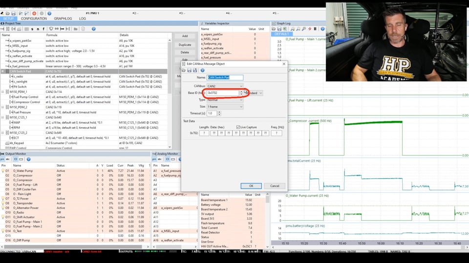
| 14:42 | This is our edit CAN bus message object. |
| 14:45 | So we've given it a name and again we want something that we can easily remember what that is. |
| 14:50 | We can define which CAN bus this is on, there are two CAN buses on the Ecumaster PMU and then we also need to define the address that that information will be available on, in this case hexidecimal Some more information about the type of information, the type of message, the way it's sent, I'll just turn this on. |
| 15:12 | Just allow our compressor to charge up and hopefully we should get some live information. |
| 15:20 | When we connect, bear with me, alright that's connected now. |
| 15:25 | One of the nice features with the Ecumaster PMUs is that we actually essentially get a live CAN analyser so what we can see here is all of the information in real time as it's occurring on that particular CAN ID 702 so we know exactly what's going on and that'll help us as well with our decoding. |
| 15:50 | I'm just going to switch that off because it's really annoying. |
| 15:53 | Alright so that's our main input there or our message object so we've defined now that we're going to have information coming in on that particular CAN ID from our CAN switch pad. |
| 16:05 | But now we want to define the actual inputs that we want to perhaps use so we've got 3 as I mentioned here, we've got a radio button there which allows me to communicate back to the rest of the team in pit lane. |
| 16:18 | We've got a rain light here and we've got a pit switch. |
| 16:22 | So these allow us to define where abouts to find those particular inputs so let's just double click on our radio button here. |
| 16:31 | So we can define which input or message object it's coming from, of course our CAN switch pad which we've already looked at. |
| 16:38 | The data format in this case will depend on what we are looking for, what message type we're looking for, in this 8 bit unsigned little endian. |
| 16:49 | We also have the byte offset so where abouts in the message we're looking for this particular input and then in this case we're only looking for a single bit inside of a byte so we are actually extracting a bit field, in this case we're looking for 1 bit and this is the position for that bit. |
| 17:07 | Depending if you are looking for a particular value which we'll look at in a second, we can also apply a multiplier, divider and a offset as well, not relevant for us. |
| 17:20 | Now again I'll just see if this is going to work without going crazy with our compressor. |
| 17:26 | We should be able to check this so let's just turn this on. |
| 17:30 | Doesn't look like it's super keen on connecting while I am live. |
| 17:35 | Alright so what we're looking for here, just to basically check, has our decoding been accurate? This is the result here, so we can see at the moment it's sitting at zero and if I press the radio button, you can see it clicks to 1. |
| 17:48 | So at the same time, we can actually see what is changing in this message so this is all of the raw data here coming through on that particular message and let's have a look back up here. |
| 18:01 | The piece of information we're interested in here is occurring on byte 4 which is this little guy here. |
| 18:08 | So again if I click the button here, sitting on 00 at the moment, I'll click the button, it goes to 80. |
| 18:13 | So we can see exactly where that particular CAN bus input is coming from so it makes it really easy for us to confirm that our decoding is correct and basically test that our result is going between 0 and 1 when we press the relevant button so pretty easy to do and really really powerful. |
| 18:30 | Quickly we'll have a look at our rain light as well. |
| 18:34 | And double click on that. |
| 18:36 | So exactly the same deal, coming from the same place, same data format. |
| 18:41 | It's actually coming from exactly the same byte of data as well but the bit position is different here and again if I click on my rain light switch here we can see that that goes from 0 to 1 so happy days, it is all working. |
| 18:57 | So that's another way we can get data into the power distribution module with a CAN switch pad. |
| 19:05 | We can also bring information in via the ECU in a CAN message too. |
| 19:11 | So in our case here, let's just jump over to our MoTeC 150 and this is again the beauty, I want to just talk about that. |
| 19:21 | We've got so much flexibility here because we are working with CAN messages. |
| 19:25 | This will obviously work seamlessly with an Ecumaster ECU but it's also working perfectly well here with a MoTeC M150. |
| 19:34 | It'll work with any brand of ECU that can send CAN messages or CAN requests so let's have a quick look here. |
| 19:40 | We are on our initial setup workbook and we are on our engine outputs worksheet so for example just a couple of the aspects that I am using here for our coolant fan 1. |
| 19:52 | So we could hardwire this up and this is again just to talk about the different options available to us. |
| 19:58 | We could have run an output from an auxiliary output on the M150 through a physical wire and we could have wired that up to the power distribution module and then set it up as a switched input just like we looked at earlier, to turn our fans on or off but here we don't need to do that. |
| 20:13 | Instead, in this case the MoTeC M150 thinks that it's connected to its own brand of MoTeC PDM so we can set our output resource here, instead of for a physical pin on the ECU, this is set up to be PDM byte zero, mask 80. |
| 20:31 | So that's basically the bit of information that is being sent out from the M150 in order to switch that particular output on. |
| 20:40 | Likewise if we come down to our fuel pump resource, we've got the same thing here, could have wired this as a hardwired output, we're using PDM byte 0 mask 01. |
| 20:51 | So it's just basically changing a bit, status bit on the output there of the CAN message that the MoTeC would conventionally send to the MoTeC PDM. |
| 21:01 | So what we need to do is decode that in the Ecumaster PMU and we are golden. |
| 21:08 | So let's have a look at how that all works. |
| 21:10 | So this comes down to our, here we go, our PDM 1 input. |
| 21:18 | So we'll just quickly look at our fuel pump control so it's set up exactly the same as the CAN switch pad. |
| 21:25 | So we start with our actual overall message object so this defines the CAN bus and the address that we'll be looking at, in this case CAN bus 2, 011A hexadecimal is the address. |
| 21:38 | So now it knows where to look, so we've set up that message object, let's have a look at our fuel pump control here so this is the actual CAN input. |
| 21:45 | Basically everything exactly the same as what we've already looked at, we can set the byte offset and the bit position, job done and again if we were switching that in the ECU, we'd see that that particular input would turn on and off. |
| 22:03 | The other one I've got, set up on this particular PMU is compressor control for the air compressor for our paddle shift so again, that is just being sent out as a CAN message to the PDM from the MoTeC M150 ECU. |
| 22:20 | Alright so we've got the analog inputs or analog digital inputs, we've got the CAN switch pad and we've got the messages coming in. |
| 22:30 | We've also got a couple of other inputs here that I just want to talk about. |
| 22:34 | We have got some inputs coming in, in this case this is coming from the MoTeC M150 for manifold absolute pressure and engine RPM. |
| 22:44 | And once we've got these defined as well, should just mention, I'll let our compressor charge up again. |
| 22:53 | We can, over on our variables inspector her see exactly what's going on. |
| 22:58 | So our fuel pressure is being displayed, we've got our manifold absolute pressure as well, our fuel pressure's dropping off of course now that the fuel pump's turned off. |
| 23:07 | We've got our RPM, obviously that is zero because we're stationary. |
| 23:12 | We'll just turn our pit switch on and we can see that our pit switch turns on and off. |
| 23:16 | So we can just basically go through all of these, our engine coolant temperature's sitting at 15°, basically make sure that all of these make sense and everything is working as we'd expect, it's a nice way of just going through and basically fact checking everything that we have set up. |
| 23:32 | Now why would you want to bring in something like manifold absolute pressure or engine RPM? Well let's talk about one that would make a little bit more sense straight off the bat is this one here, we are bringing in engine coolant temperature. |
| 23:45 | Now obviously we can use that for controlling the operation of a thermofan. |
| 23:51 | So this goes one step further and again really sort of comes down to, they're so flexible in how you use a power distribution module, there's no single right way you must use it so if we want to talk about our thermofans for example we could wire a coolant temperature sensor directly to the power management unit. |
| 24:11 | It might make a lot of sense if we are running a carburetted engine with no ECU controlling it. |
| 24:16 | We would normally though have with an EFI engine, our engine coolant temperature sensor going straight to the ECU. |
| 24:23 | That's then giving us two options. |
| 24:25 | We can send engine coolant temperature straight out to the power management unit which is what we're looking at here and then control the thermofan switching in the PMU, or we could use an auxiliary output from the ECU, either hard wired or via a CAN message to do the same thing so lots of different ways of skinning the cat so to speak. |
| 24:44 | Now I also want to talk about the last CAN based option here which is a CAN keypad. |
| 24:52 | Not to be confused with the CAN switch pad which we've already covered. |
| 24:56 | In this case we're using the Blink Marine, in this case, what's it got, 8 keys on the keypad, probably also seen the Grey Hill ones which are used by the likes of MoTeC and Haltech. |
| 25:09 | So these provide a really easy way of integrating a range of control options directly into the PMU. |
| 25:17 | So if we double click on this, we will see that that brings that up. |
| 25:21 | We can define a particular control for each of these buttons and how it will work, whether it's latching or not. |
| 25:29 | Once we've done that we can then make use of these keys inside of our control function. |
| 25:35 | So really easy way to get a lot of control straight into the PMU with only the requirement for again 4 wires. |
| 25:44 | Feed power, earth, CAN high and CAN low up to the keypad and your job is done. |
| 25:49 | Alright so we've talked about our inputs, now we want to talk about our outputs... |
| 25:53 | Cue our compressor control and actually while our compressor's running, and it switches off, that's absolutely perfect, let's just pause our logging for a second here and we can come back over here and see, no that's actually not going to give me what I want to show you. |
| 26:12 | Alright let's talk about our output monitor which is down here in the bottom left hand corner. |
| 26:16 | So this is where we define all of our outputs so on the PMU we've got a range of outputs that are able to support up to 25 amps of continuous operation and we've got some smaller ones that are rated up to 15 amps of operation. |
| 26:32 | And it's really important to understand when you are wiring up the power management unit what the requirements for a particular circuit are going to be. |
| 26:42 | Usually pretty easy, manufacturer of a component like the compressor that we keep hearing switch on and off in the background, a fuel pump will give you information based on what the power draw, current draw I should say is going to be for that component. |
| 26:57 | So that gives us a pretty good idea of understanding what it's going to require. |
| 27:02 | We can also use ohm's law as well to work out for a given impedance in a circuit, and a given voltage what the current draw is going to be. |
| 27:11 | So let's have a look at a couple of these here. |
| 27:14 | So in this case, if we start by double clicking on our water pump. |
| 27:17 | So of course we can give it a name, pretty self explanatory there. |
| 27:23 | We can choose the output that it's going to be on and we can see that some of these are 25 amp and others are 15 amp just like I explained so in this case for the water pump, electric water pump we're running that on a 25 amp output. |
| 27:34 | Now we can define what the maximum current is going to be. |
| 27:39 | So we've got a couple of aspects here. |
| 27:41 | We've got this first one which is our in rush current, so I've set that to 30 amps so when we switch on something like a water pump or a fuel pump, basically what we're going to find is the moment we switch it on there's going to be a massive spike in our current and then once the component, once the fuel pump or water pump starts actually turning, we'll see that that current drops off quite sharply back to its normal operating current so this is called in rush current so we can protect the normal current draw while still allowing for this in rush current so we can see there, 30 amps for a time period of 1 second which is pretty generous. |
| 28:22 | Then we actually look at our maximum operating current. |
| 28:26 | So in this case 15 amps, that's what I expect that water pump to draw. |
| 28:29 | If we go over 15 amps then something is probably wrong and we need to consider what we're going to do about that, I'll come back to that but let's just have a look at the current draw, so we'll just, we are still stopped are we? We'll pause there, we were paused. |
| 28:48 | Alright so we have got our water pump current being logged here and we can see the in rush current aspect, if I just zoom in a little bit, we can see that our in rush current hits a peak of about 20 amps, let's call it 20 amps and then drops away to, it's moving around a little bit, let's call it probably an average of about 7.5 amps. |
| 29:12 | Let's turn that off. |
| 29:14 | So using the logging, it's really easy to actually set the switching, the fusing up so that you're protecting against the normal current draw that you would expect to run and in this case, probably if we're seeing 7 amps, 15 amps is probably a little bit higher than it really needs to be. |
| 29:36 | But at the same time if we end up with a dead short or something of that nature, we're going to spike that current right up to the maximum straight away so it's still going to protect us. |
| 29:46 | Now we get onto the trickier part which is our ability to wait and then retry that circuit so this is this section here so we can set a retry count. |
| 29:59 | In this case if this particular circuit exceeds 15 amps, what it's going to do is shut that circuit off, it's going to wait 4 seconds which is our retry every second, in this case 4 obviously and then it's going to continue doing that up to 10 times before it finally decides all hope is lost and it shuts it off completely. |
| 30:20 | If you've got something really mission critical, and we could absolutely consider that water pump to be mission critical, you could also choose to click retry forever. |
| 30:28 | Do need to be mindful here between the maximum current and the wait time as well, we still need to protect that circuit but the power management unit is going to shut that circuit off straight away when we do get to that maximum current. |
| 30:44 | Alright so that's basically the simple side of what's actually, how we set up an ouput but we also need to understand what's going to switch that on and off and in this case we've got a few options. |
| 30:59 | So we can set default, which is where we can just set the output to be always on or always off. |
| 31:06 | So if we require full time power to a component that might be a nice easy solution to do exactly that. |
| 31:13 | We've got exactly that for our transponder as well as power for our telemetry as well as power for our alternator which are these 3 components down here. |
| 31:26 | So don't need to do anything tricky there, those are just always on. |
| 31:31 | In this case, I'm using a channel to control the output which is called EWP, electric water pump pulse control, talk about that in a moment. |
| 31:40 | Or the third option is that we can use a formula to control the output. |
| 31:45 | So again really it's up to what you're trying to achieve as to the correct way of doing this but once you want to get a little bit more involved with your options, you're probably going to use a specific channel or function or you're going to be using a formula to control it. |
| 32:02 | Let's shut this down, before we do that just take note again, our output control as a channel, electric water pump pulse control, let's have a look and see what exactly that's doing. |
| 32:13 | So we'll find that out here, which is a function so the little F at the start there means it's a function that we have configured. |
| 32:22 | Let's double click on it and see what it's doing. |
| 32:26 | Alright so we've got a name for it, obviously we already understand what that is and this is defining when this channel, this function is going to be effectively on. |
| 32:36 | So the first is that we're going to use a function called flash. |
| 32:42 | So basically this turns on and off and in this case, that flash will be 10 seconds on and then 30 seconds off. |
| 32:50 | If our engine coolant temperature is below 50°C. |
| 32:54 | Right so that's our first one there, if we're below 50°C, this is going to constantly turn on for 10 seconds then it'll turn off for 30 seconds and then it's going to repeat. |
| 33:04 | Or move to this next one, if our engine coolant temperature as you can see here is between 50° and 70°C, we're going to change our on and off parameters. |
| 33:15 | Now it's going to be on for 10 seconds and it's going to be off for 10 seconds. |
| 33:19 | However if we are over, got this out of order but if we are over 80° then our water pump will be on 100%, basically full duty and in between there, between 70 and 80° we're on for 5 seconds and off for 1 second so why are we doing this? What it does is it controls the water pump, not too dissimilar to how the electric water pump controller does, basically turning it on and off to circulate water slowly to start with so that it allows it to come up to temperature and then as the water does come up to operating temperature, we're turning it on more at the time, basically to allow it to circulate. |
| 33:59 | Without this, if we just had it on the whole time, we would end up with problems with basically getting the engine up to operating temperature. |
| 34:08 | So again you can be as clever with this as you want. |
| 34:12 | We did have another function where we were controlling this, pulse width modulated and this is a problem, a lot of power distribution modules will not offer pulse width modulation for an output which is where we can turn it on and off very quickly, you can think of this like a light dimmer which makes a lot of sense for something like an electric water pump. |
| 34:35 | By using pulse width modulation we can really slow the pump down and then as the water temperature comes up we can speed the pump up. |
| 34:41 | The problem, and this is why a lot of power distribution modules don't offer pulse width modulation is that the switching like this does create a lot of heat in the transistor that does the switching and if you're switching something that's relatively high current load like a electric water pump, can result in over heating which is exactly what we had happen. |
| 35:00 | Alright so that's our first function there which we wanted to look at there which is our electric water pump. |
| 35:06 | Let's look at our fuel pump and we'll see how that's operating, so we've actually got 3 fuel pumps here. |
| 35:13 | We've got our lift pump and then we've got two high pressure pumps which are fitted to our surge tank. |
| 35:18 | So if we double click on this, we can see pretty much everything we've already talked about, we've got our in rush current, our maximum current and our in rush time. |
| 35:26 | Retry count and how many seconds we're going to wait. |
| 35:31 | This time though we are using a formula which we can see there is our fuel pump control which is coming in from our ECU so basically when the fuel pump control is on, it will run that output so pretty straightforward there. |
| 35:47 | Also quickly look at our compressor and this is a little bit different here, so this is our air compressor, the one that you've been hearing switch on and off. |
| 35:59 | So if we are in a situation where our current draw is exceeding what we can get away with with a single output, well easy enough, we can just double them up and sometimes we may want to use more than two. |
| 36:12 | So here we've got our pin, in this case we can see we've selected double, we can triple as well and the only thing we do need to be mindful of is we have to use pins that are a matching current handling capability. |
| 36:25 | So we can't use a 25 amp output with a 15 amp output. |
| 36:29 | We've then got the two outputs that we are using, in this case output 2 and output 3, of course both 25 amp. |
| 36:35 | One thing which we haven't actually done here which is always good best practice is if you are doubling up components like this, I would suggest splitting the current load between outputs that are further away from each other, so what that means is essentially if we look at the header plug, output two and three are both at one end of the header plug, the transistors are both on the same end of the board and if there are drawing a high current it's going to create high localised heat. |
| 37:03 | So basically a bit of load balancing in terms of the current draw on your outputs is always a good idea. |
| 37:09 | Just to even out the heat that will be created on the board itself. |
| 37:13 | Alright so our in rush current in this case, probably doesn't need to be anything like this at the moment but initially with this output we were having, we had this wired up to a single output and on paper we should be able to get away with it. |
| 37:31 | We were seeing the in rush current hit between 80 and 90 amps which is scary high but this only occurs for milliseconds and then the steady state current that it would draw once it's operating was between about 18 and 20 amps so should on paper be well within the capability of a single 25 amp output. |
| 37:51 | However with an inductive load like this, particularly one drawing 20 amps, creates a lot of heat in the transistor when it's switching off so basically what it would do is overheat that output and it would switch off so we ended up sharing that load between two outputs, that's worked really well. |
| 38:10 | Got another aspect that I am using here which is optional is this pulse width modulated configuration. |
| 38:17 | I've already briefly talked about it with regard to the water pump and that would be where we set a specific frequency that we're operating the output and then using a table we could then change the duty cycle based on our engine coolant temperature. |
| 38:32 | In this case though what we're using is soft start. |
| 38:36 | So that's this function here. |
| 38:38 | So basically with an output like our compressor we saw as I mentioned very high in rush current, 80 to 90 amps and that was causing some other knock on effects with our charging system on the entire car, basically when that switched on we were seeing our battery voltage momentarily drop quite low and by setting up this soft start and basically ramping it from 0 to maximum over in this case, what are we 500 ms, I thought it was a little shorter than that, so half a second there. |
| 39:10 | Basically what that allows us to do is reduce or eliminate that in rush current so again if we just turn this on, we'll get out of this for a second. |
| 39:23 | And we'll set our logging to go and we'll come over so that we are live. |
| 39:28 | Let's just turn that off and back on. |
| 39:38 | So what we can see here, if we're looking at our compressor output, this is being logged at 500 Hz so reasonably quick so we can really see what's going on, I switched it off here so I didn't actually get back to zero before I switched it on. |
| 39:50 | We see that our in rush current hits, if we look at this part here and I'll circle it, 43 amps so still pretty high and then it drops back down to 20, 21 amps. |
| 40:04 | What I'll do here is we'll just adjust the properties of this and I'll see if we can turn our peak current off. |
| 40:17 | In this case, yep, sorry we'll turn our soft start off. |
| 40:22 | And we'll see how that works out. |
| 40:24 | So let's go back into our output. |
| 40:26 | And we will disable pulse width modulation and we'll click OK. |
| 40:32 | We'll just flash that into the PMU and we'll make sure we are recording. |
| 40:36 | We'll just function the paddles here so we can use a little bit of air. |
| 40:42 | And there we go. |
| 40:46 | We'll turn that off because it's quite loud so we can see our peak current there, our in rush current, what are we, 97 amps. |
| 40:55 | So you can see the effect that using that soft start has and it's something that I think a lot of people overlook so really important to just understand that functionality is there. |
| 41:04 | And can help reduce the instantaneous current draw on our components. |
| 41:10 | Right so I think we've talked about most of these aspects now, the way we can control them. |
| 41:18 | We're going to jump into our Q&A in a moment so this is probably a pretty good time to mention if you've got any questions, please start asking those and we'll jump into those shortly. |
| 41:29 | I do just want to quickly show you here, I have actually changed this. |
| 41:36 | This table here was how we were using the duty cycle control for our electric water pump. |
| 41:42 | Unfortunately I've ended up changing around the output here so it's now calling it compressor control but basically what we had on this table here was our engine coolant temperature and we could change the duty cycle of that output and our electric water pump based on that. |
| 42:00 | Now again that was overheating, an option to get around that would have simply been to do what I've done with the air compressor which was to split it across two 25 amp outputs and that would have worked quite nicely so it is something you do need to be mindful of with these higher inductive loads where you may actually, particularly if you want to pulse width modulate, you can actually exceed the capability of a single output even while on paper it should be OK. |
| 42:26 | Right I want to just talk about fan control as well so let's have a look at our fans. |
| 42:37 | Where is our fans? They're not on this one, that's probably why. |
| 42:42 | So don't worry about our fan control. |
| 42:44 | We've talked about our fuel pump control though and our diff pump is the other one that I want to look at here. |
| 42:51 | So we've got a channel coming through here which we already looked at which is from an analog input which is our channel that's controlling this, we call that diff pump activate. |
| 43:00 | So our diff pump will activate whenever that channel is active so pretty straightforward there. |
| 43:08 | There is something else I wanted to show which... |
| 43:13 | I think yeah I've got it, we've got two power management units on this particular vehicle and the function that I wanted to show is unfortunately on the other power management unit so I can't show you that. |
| 43:28 | However I'm going to just talk through, just again to give you a little bit of an idea on the flexibility that we have with how these work. |
| 43:35 | Alright so talking about our coolant fans so first of all we've got the ability to run the coolant fan purely off the CAN keypad which is in front of me here. |
| 43:44 | So I can press a button on that and that will turn both our radiator fans on. |
| 43:48 | The other way we can do this is we've got the CAN message coming through for the MoTeC M150 ECU so that will tell the PMU when to switch the fans on and off so we can do that of course inside the MoTeC software, we can set an on coolant temperature threshold and some hysteresis. |
| 44:08 | The other thing that I wanted to do here, because we come into the pits for a pitstop during a race and obviously everything is scorching hot, we come to a stop and our driver change takes around 30 seconds, so there's a lot of heat soak occurring so I wanted to get a bit of a running start on that and basically any time I've got the pit limit switch on, which is this one here, and we'll actually be able to hear these start up. |
| 44:35 | It helps if I turn the car on when I do this, let me turn that on. |
| 44:39 | When I turn that on, basically the two fans start running straight away. |
| 44:44 | So as soon as we're in a situation where we're in the pit lane and we're on the pit limiter, the radiator fans are going to run so again there's so much flexibility with how these work just based on your own preferences and what you're trying to achieve. |
| 44:58 | No right or wrong way of doing them but you can start doing some pretty clever things with these. |
| 45:05 | Right last part I want to talk about is logging here. |
| 45:09 | Because conventionally, and this is another one of those advantages we have with the power management unit. |
| 45:14 | Conventionally we're pretty blind to what's actually going on inside our circuits. |
| 45:18 | We don't know what the voltage is and we don't really know what the current draw is in a particular circuit but we can get quite granular with our power management, few different ways we can do this. |
| 45:28 | So while we are live with the power management unit, again on my laptop screen we've got our log graph here where we can see exactly what's going on for all of our channels. We can log all of that in real time while we are connected. |
| 45:42 | You can actually log to the PMU depending on the specific PMU you've got as well if you want to set up logging. |
| 45:49 | My own personal preference though is I like to keep all of my logging in one place wherever possible. |
| 45:56 | I don't want to be retrieving log files from an ECU then a dash, then two power management units so nice thing with the PMU is it does send all of the information out as a CAN message in terms of loads, currents, voltages on all of the outputs so we can configure those into our MoTeC C125 dash and if we head over to that, just quickly show you through that, into our communications here, got a lot of information coming into this. |
| 46:27 | But Ecumaster PMU there. |
| 46:31 | So I've got configured here our electric waterpump current, radio, our rain light, I did have a surge pump in there that's no longer there. |
| 46:39 | The fuel pump, gearbox pump and our diff pump current. |
| 46:42 | Pretty easy to set that up. |
| 46:44 | Once we've got that set up we can log it. |
| 46:46 | In our particular vehicle as well we are also running telemetry so we actually send that information out live while the car is on the track. |
| 46:54 | So that comes through and looks a little bit like this page here that we're looking at. |
| 46:59 | I think if I go back up to telemetry we also have that set up as a page, electrical current and electrical voltage. |
| 47:09 | So that's going to be monitored live. |
| 47:13 | Now regardless whether you're monitoring this live or you're looking at historic data over the life of the car, this can also give you one other advantage that's easy to overlook, you can start to see if a component is on its way out. |
| 47:24 | So if we're talking about maybe our diff pump or our gearbox pump, we know that traditionally that might be drawing 3-5 amps. |
| 47:32 | If we start seeing that drawing 7, 8, 9, 10 amps, that is a bit of a red flag that something is not right there. |
| 47:39 | We've actually seen this ourselves when we had a blockage in one of our filters and we wouldn't have known that necessarily, well there were 2 aspects that made us aware of it, one was the diff temperature in that case got hot, I think it was diff temperature, could be gearbox but either way. |
| 47:57 | The diff temperature got hot which obviously brought our attention that something was wrong with that cooling circuit and then by looking at the current of the diff pump or the gearbox pump, whichever one it was, we could see that that was really really high and that gave us an area to look at. |
| 48:13 | So it can just help in the heat of battle, focus your energies on exactly where your problem lies and save you a lot of time. |
| 48:22 | Alright we'll get into our questions and remember if you do have any more, keep those coming and we'll see what we've got in here. |
| 48:31 | First question comes from Bjorn who's asked, considering the thermo fan, can the PDU also pulse width modulate the electric fans? Yeah absolutely it can do. |
| 48:40 | Basically it can pulse width modulate any of the outputs. |
| 48:44 | Same thing goes though, just be mindful of the fact that you can end up having problems with the heat being generated in some of those transistors if you are pulse width modulating. |
| 48:56 | The amount of heat created is also dependent on the frequency that you are using for pulse width modulation. |
| 49:04 | Fly back diode can be beneficial if you are on the limit there but what I would suggest, just from my own experience, if you want to do something like that, I would suggest just doing a quick and dirty bench test, wire it up temporarily, the particular output that you are wanting to run and just put it through its paces on the bench and make sure that you can get away with the output that you want to use. |
| 49:26 | For example our compressor there where it became pretty obvious that we were not going to be able to run that off a single 25 amp output even though on paper it should have been OK. |
| 49:36 | If you're creating a milspec wiring harness where everything's sealed, that's pretty difficult to come back from so it's always nice to just bench test your higher load outputs and make sure that if they're trying to do anything tricky there that they are going to be fine. |
| 49:51 | Torq Hub Media's asked, sounds like using a PDM is a good way to try and preserve some I/O on the ECU by way of things like thermo fan? Yeah absolutely, I mean you're going to free up a lot of outputs for sure for things like your thermo fans and your fuel pumps. |
| 50:08 | Obviously this is all dependent on your ECU being able to send those requests via a CAN message, not every ECU can do this but these days it's rare to find an ECU that doesn't have CAN capability so you do want to check before you commit to that but in most instances, yeah and it's going to save you time as I mentioned as well with your wiring, it's also going to reduce the complexity of your wiring harness. |
| 50:33 | BlackRex has actually put up a great point, could you set an engine speed requirement for the compressor so that it doesn’t constantly run? Yeah absolutely, you can do whatever you want but that would have definitely stopped the frustration there of it switching on and off while I'm trying to sit here talking. |
| 50:52 | Suhas has asked, in what circuits do you recommend using a protection diode when wiring a PDM? So in most instances it's not going to be a requirement. |
| 51:03 | What I would suggest is when you are using a PDM, before you get to a point of doing any wiring, you want to familiarise yourself pretty thoroughly with the instruction manual from the PDM supplier. |
| 51:16 | They're all going to be a little bit different but basically a good understanding of what they're asking you to do. |
| 51:22 | So specifically for the Ecumaster PMU, and I've touched on this, if you want to pulse width modulate the output they do recommend that a fly back diode may be beneficial there so something to keep in mind there. |
| 51:35 | Manitoublack's asked, while the Haltech Nexus was the first, do you expect or know of other ECU manufacturers likely to follow suit in the near future with an ecu+PDM combo unit? And also, do any PMU's offer variable voltage output for variable speed control as opposed to just PWM? OK I am currently not aware of any other manufacturers coming to the party with a combined PDM ECU, I mean it makes a bit of sense to me getting those two modules together. |
| 52:08 | There are some pros and there are some cons, there's some flexibility in being able to for example locate two PMUs in your car, maybe one at the front of the car where it's closer to the outputs you're wiring it to, another one maybe in the rear. |
| 52:23 | Personal preference here, yeah it'd be interesting to see if time will tell whether other ECU manufacturers jump on that bandwagon. |
| 52:31 | Variable voltage essentially pulse width modulation is the way that we get a variable voltage from a transistor, it's switched on and off at a high frequency or basically any frequency we control and it's essentially, I liken it just to a light bulb dimmer, that's exactly what we're doing. |
| 52:50 | By changing the frequency and the duty cycle that we send to the light bulb we can control it from full off to full on and anywhere in between. |
| 53:00 | Suhas has asked, what would be the total current draw while running the car and what would be the max current draw while cranking? OK so first of all, cranking we're not monitoring. |
| 53:10 | When you are wiring up a PMU, the cranking current draw is going to be massive. |
| 53:17 | Like very very high and we don't wire that through the power distribution module. |
| 53:21 | As far as the starter motor goes, what we do is we wire the starter motor solenoid which is lower current draw, perhaps in the region of 10-20 amps, that gets wired up to the power distribution module but the actual main feed to the starter motor will conventionally come straight from the battery positive and you've probably seen the size of the cable that will go to a starter motor, wouldn't be surprised to see well in excess of 200 amps cold cranking particularly with maybe a high compression engine so yeah not through the power distribution module. |
| 53:57 | What would the total current draw be though, I mean it depends on your particular setup and what you've got going through it so I can't tell you off the top of my head what maximum current draw the PMU16 is capable of, you can look at the specifications, it'll tell you, you want to make sure that you're specifying your circuits and separating them so that you are within the capabilities of the unit, obviously that's sort of power distribution module installation 101, matching your loads to your circuits on your, your outputs I should say on your power management unit. |
| 54:35 | Couple of questions that are pretty similar, Che's asked, can a PMU also control the creature comforts such as power windows, power locks, radio head unit etc, electric power steering and climate control. |
| 54:49 | And Torq Media's also asked, how do we look at body control functions like switching hi/low beam headlights or a flashing output by way of indicator/hazard light? So two slightly different angles so let's talk about Torq Media's question. |
| 55:00 | Headlights, pretty easy, I mean all it is is an understanding of the wiring diagram for your headlights. |
| 55:09 | You're going to have park lights, low beam and high beam and basically you would wire an individual output for each of those and then you've got complete control of them. |
| 55:18 | You could wire either your control stalk from your vehicle up as an analog input to control those or this could again come from a CAN message from a CAN keypad, however you want to do it. |
| 55:31 | Then you've got individual control over your park light setting, your low beam and your high beam. |
| 55:37 | You see functions where on race cars, and we've actually got this little switch here. |
| 55:45 | This is labelled as lights and if I click that, what that conventionally was going to do until we removed the headlights was flash the headlights to warn a car ahead of you that you're coming up behind them. |
| 55:57 | Indicators again really easy, we'd just wire up to the individual indicators, the indicators on the left would be on one output, the indicators on the right would be on another and using a flash function we can then turn the indicator on for a set period of time and off for a set period of time so pretty flexible with that. |
| 56:16 | Che's question there, creature comforts, power windows yeah I mean basically it's all just a case of wiring up an input to control it, in this case you've got switches for your power windows and then the output which will go direct to your power window motor so yeah absolutely. |
| 56:33 | Climate control's a little bit different, it really depends on how that is wired up, how that actually works in your vehicle. |
| 56:41 | What you'd probably find is that the actual climate control system is very integrated with the air con unit, the fans etc but you could provide the outright power to the climate control unit from your power management unit so it really depends on the unit. |
| 56:59 | Next question and the last one for today, can PMUs correlate health metrics like amp usage and temp to create custom alarms? Yeah absolutely I mean you can create alarms based on a current draw situation. |
| 57:17 | Health metrics over the life of a component though that's a little bit trickier, you'd need something that could actually learn that, well a year ago this unit was drawing 3 amps and now it's drawing 5 or 7 amps, that's probably a little bit trickier to do but yes you absolutely can set up alarms to bring your attention to the fact that your current draw is above a certain level so again just really depends what you're actually trying to monitor and how you want to do that. |
| 57:46 | Can't probably add too much more to your question there unfortunately. |
| 57:49 | Alright that's brought us to the end of our lesson there and remember if you're watching this in our archive at a later point, if you've got further questions, please feel free to those in the forum and I'll be happy to answer them there. |
| 58:02 | Thanks for joining us and we'll see you all next time. |
Timestamps
0:00 - Introduction
0:26 - Software overview
2:10 - What is a PDM?
3:43 - Advantages over conventional fuses and relays
7:44 - Analog/digital inputs
12:46 - CAN switch pad input
19:05 - CAN based input
23:31 - Fan input
24:44 - CAN keypad
26:11 - Water pump control
35:05 - Fuel pump control
35:47 - Compressor control
41:30 - Duty cycle control
42:26 - Diff pump control
43:26 - Operational flexibility
45:05 - Logging
48:30 - Questions


