298 | Terminating Shielded Cable
Summary
Shielded cable is a critical element in protecting mission critical signals from electromagnetic interference. In order for the shield to do its job, we’re going to need to terminate one end so it can drain to ground. In this webinar, we’ll look at the options available and demonstrate how it's done.
| 00:00 | - Hey team, Andre from High Performance Academy here, welcome to another one of our webinars. |
| 00:04 | This time we're going to be having a look at the options when it comes to terminating shielded braided cable. |
| 00:11 | Now this is something that isn't overly complex and I expect this is probably going to be a relatively short lesson so if you do have questions, as usual, we will be having a Q&A session at the end. |
| 00:23 | I'd suggest if you do have questions, chuck them in there reasonably early. |
| 00:26 | I will put a call out as we go through but as I've said, this is probably going to be a little bit shorter so a little bit less chance for you to get those in and I wouldn't want you to miss out on them. |
| 00:35 | Alright we'll start with what is shielded cable? So I've got a couple of lengths here that I'm going to use for this demonstration and it's not particularly complex, it is simply a shielded braid that goes around the conductors inside and what that allows us to do is provide some protection to the signals that are going to go through those conductors. |
| 00:58 | So provides electromagnetic interference rejection or protection I should say, for the conductors that go inside there. |
| 01:07 | So we will see shielded cables used on most of the mission critical sensors on the engine management system. |
| 01:15 | Particularly the most common places you'll see that would be engine speed, engine position, camshaft position sensors so obviously the information that the ECU is receiving from those particular sensors is absolutely critical to the operation of the engine management system and the engine itself so any noise there that's going to affect the quality and reliability of that signal, we really need to do our best to reject that and get rid of it, so that's why that shield is used. |
| 01:44 | Other places you will likely see shielded cable used would be basically anything that's a high frequency signal or relatively high frequency signal. |
| 01:53 | Knock sensors we'd generally make sure that those are run in shielded cable and also wheel speed sensors. |
| 02:02 | Now a lot of people run a lot of other sensors inside the shielded cable as well, I've seen even in OE applications, shielded braid is often used for the likes of drive by wire wiring. |
| 02:16 | Not something I personally use but it's one of those situations where there's not necessarily a black and white line in the sand on when you must use it so you'll see it in a variety of different places. |
| 02:26 | However the application of it is not really our main priority here, it's about understanding what we need to do with it when we are working with it. |
| 02:33 | So first of all, the cable itself, this is available as you'd expect in a range of different conductor configurations and I'm talking here about the number of conductors that are inside it. |
| 02:46 | I think, as we'll find out, I think this is the 3 core and this is 22 gauge as well. |
| 02:52 | So basically available to suit just about anything you could imagine. |
| 02:58 | So if you're dealing with a variable reluctance or magnetic sensor then those are only 2 wire so in that instance, you would only need a 2 conductor core. |
| 03:08 | If you are dealing with something like a Hall sensor then generally I would be using a 3 core shielded cable for those, basically keeps all of the wires in there. |
| 03:19 | Even though with a powered sensor like a Hall sensor, not really so worried about the power to it. |
| 03:27 | it's the actual signal wire that we want to shield but for simplicity and neatness with the way we're wiring it up, obviously using a 3 core shield makes a lot of sense. |
| 03:38 | So why do we need to terminate this braid and where should this be done? So what I'll do for a start is just get this under our overhead and we'll just cut a section of the shielded cable off so we can see what's underneath. |
| 03:55 | Now I'm going to use a sharp razorblade here, there is actually a tool for doing this which is called a ringing tool. |
| 04:03 | Ideal make one of those and as its name implies, it's actually ideal but I don't have one here so we're going to do it the old fashioned way. |
| 04:10 | You do need to be a little bit mindful if you are using a razorblade or a knife here though because if you are a little bit too generous with the blade, you are liable to cut through some of the strands of the braid underneath so I've just basically cut through that, doesn't require much pressure, you can just run it around as you saw me do and then by bending it backwards and forwards we can see that that breaks free and we've got that plastic sheathing basically exposed. |
| 04:34 | Now I'm going to just run that razorblade down the side there and that'll do exactly the same just splitting that and let's see if we can now get that out of our way. |
| 04:45 | So that's the braid that we see around the outside of our conductors and yep we are a 3 core on this particular example. |
| 04:55 | Alright so that's the shield itself that we can see there in a braided configuration. |
| 05:01 | But what we're going to do is terminate this to our ECU so that any electromagnetic interference anything that's basically been absorbed and conducted through that shielded braid can be then drained to ground and if we don't do that, it's basically not going to serve its purpose so that's why we need to terminate it. |
| 05:24 | It's also important to understand where we want to terminate this. |
| 05:27 | So we want to make sure that we are only terminating it at one end and that would almost always be at the ECU. |
| 05:37 | What you'll find is that typically the ECU's wiring diagram's going to give you some instructions on where that should be and if we just jump across to my laptop screen for a moment. |
| 05:48 | This is an example from a Haltech Elite 2500 but every ECU manufacturer's going to have the same so we can see here the wiring for the trigger input, so the crank input and also the cam or home input in Haltech lingo, you can see those wired up to the ECU and what we can see here is in this location and in this location, we've got a connection that's demonstrated, basically doesn't really matter where that comes across but you can see that that is a dedicated pin there, pin 15 which is labelled as a signal ground. |
| 06:24 | So there's where that particular shielded cable needs to be terminated to on the Haltech ECU and you can basically refer to your own ECU manufacturer's instructions to find out where that should be. |
| 06:39 | I see a question that pops up quite often about whether we should terminate at both ends of the shielded cable and no we don't want to do that. |
| 06:48 | For one reason, that's going to basically ruin our star earthing strategy as well so we don't want to be doing that. |
| 06:57 | We only want to be earthing at one point which should be the ECU's dedicated shield drain wire. |
| 07:03 | Now another place where we might get ourselves in a situation where we need to terminate that shield is if we are passing a shielded cable through a bulkhead connector maybe an autosport connector or something of that variety. |
| 07:16 | So I think I have an example wiring harness here. |
| 07:23 | So with this particular harness here, this is the entire engine harness. |
| 07:28 | So we've got our ref and our sync sensors on this. |
| 07:31 | Which are these 2 smaller autosport connectors here. |
| 07:35 | Again this is 2 core shielded cable for a reluctor sensor. |
| 07:40 | So that runs up to these autosport connectors that go to the bulkhead. |
| 07:43 | What we need to do here is basically terminate the shield, then we want to pin the shield through the autosport connector. |
| 07:52 | We'll reterminate it to the shielded braid on the other side and then continue because we may still have a 500, 600, 700 mm run of wire from here to the actual ECU header plug. |
| 08:02 | So that's the 2 scenarios we would be looking at but basically the techniques are exactly the same irrespective of what we're doing here. |
| 08:13 | Alright so we're going to look at two options of doing this and really it comes down to personal preference as to which of those you want to use. |
| 08:21 | The first of them is going to be using an open barrel splice, open barrel crimp and crimping our shielded braid into a single drain wire so let's have a look at how we're going to do that. |
| 08:35 | We'll go to our overhead shot again. |
| 08:37 | So we'll basically pick up where we left off and I'd just push that shielded braid down a little bit and you see it sort of bulges out here and what we want to do to start with is basically take a scribe or a pick here, we're just going to gently make a little bit of a hole in the bottom of that shielded cable and what we want to do is basically get in here and extract out our individual conductors out of there. |
| 09:04 | Now it's a bit of a fiddle exercise and it's always fiddlier of course when you are doing this live on camera but bear with me. |
| 09:12 | So there we go, we've got 1 of those out of there now. |
| 09:15 | We'll just bend that around a little bit more. |
| 09:17 | We want to obviously be mindful of not doing any more damage to that braid than we absolutely need to. |
| 09:23 | But a little bit of damage is usually just about inevitable. |
| 09:26 | And then we'll get our third and final conductor out here. |
| 09:33 | And there we go. |
| 09:35 | Alright so basically teased a little bit of a hole inside our braid there and we've got our 3 conductors out. |
| 09:42 | So now we've got our braided shield sticking out to the side and what we're going to do is basically just twist that back together so it's all about as neat as we can get it and essentially we're going to basically consider that as another conductor strand and we're going to terminate that into a single wire so let's see how we can do that, we'll leave that there. |
| 10:06 | What I've got is a section of 20 gauge wire here, Tefzel wire that I've already stripped some of the insulation off and we're going to be using that along with a open barrel splice here. |
| 10:21 | Let's just get our open barrel splice into our crimp tool. |
| 10:27 | Get that located there, again this is always a little bit more tricky to do when you're trying to do it live. |
| 10:34 | Now I'm going to feed the braid through that which again could be a little bit tricky but it's actually gone in there quite nicely. |
| 10:43 | And we're then going to feed our single wire into the back of this. |
| 10:47 | Now what we're going to be doing once we crimp down on this is we're going to be folding this back over the white sheathing that goes around this wire so a little tip here is we don't want to end up performing this crimp tight into where we cut through that plastic sheathing, we want to leave a little bit of extra room and that's going to just allow us to bend this back on itself without creating any excess stress or undue stress and strain. |
| 11:13 | Alright so we've done that there, it is definitely not my finest work but you'll probably still get the idea from it. |
| 11:20 | What we're going to do now is just cut off our excess braid, even that up a little bit and now we've got a wire nice and securely attached to that braid that we can then easily terminate in either an autosport connector or AMP superseal, whatever we want to do. |
| 11:39 | So what we're going to do as I mentioned, we're going to bend that back on itself. |
| 11:43 | And we're going to just get that located so we've got all of our wires coming out the same way and we're going to then apply a little bit of SCL heat shrink so I've got that here. |
| 11:53 | So this is a dual wall semi rigid heatshrink. |
| 11:56 | So as it is recovered down it's going to basically become pretty stiff and that's going to provide some mechanical strain relief, it is a glued heatshrink so it will also seal itself quite nicely as well. |
| 12:08 | So we'll get that into position, get our heat gun turned on here. |
| 12:13 | And we'll just let that recover down and have a look at our finished result. |
| 12:19 | So this is a reasonably neat way of doing it, it's relatively easy, doesn't require any specialist tools or equipment and it does work very well but we will look at another option as well. |
| 12:32 | Alright let's just get that turned off. |
| 12:35 | Alright so there we go, you can see there is a little bit of bulk in this because obviously under that SCL heatshrink we are hiding an open barrel splice. |
| 12:46 | So there's some required size in that open barrel splice and that's going to end up getting a little bit chunky around that particular point. |
| 12:56 | This is a consideration if we are running multiple shielded cables. |
| 13:01 | Let's say we're in that situation where we've got an engine speed, an engine position, maybe a couple of cam position and maybe 2 knock sensors. |
| 13:09 | So we're going to have a splice like that for each of the shielded cables and as you could understand, there's going to be quite a lot of bulk around that are where they all sort of coincide together. |
| 13:20 | Another thing we do need to be mindful of when we are terminating these shielded cables, obviously the exposed section of wire no longer benefits from the electromagnetic interference protection of the shield. |
| 13:34 | So we need to be a little bit mindful of making sure that this isn't excessive in length, we don't want it to be any longer than it needs to be so it's fair to assume that we're going to end up with these probably all stacked in pretty close proximity at the ECU header plug or behind our autosport connector. |
| 13:51 | So we'll look at our second option now which is a little bit neater and a little bit tidier which is using a solder sleeve. |
| 14:03 | So this is a good time to remind you, if you've got any questions, ask those, we're going to go through this second demonstration and then we'll jump straight into those questions as I mentioned. |
| 14:13 | Bit of a simpler webinar and a little bit shorter. |
| 14:16 | So I've just used a term that if you've followed HPA for any length of time, you might be surprised at, that term was of course solder. |
| 14:25 | And in general, we consider solder to be something that in most instances we want to stay away from with motorsport wiring. |
| 14:33 | So why would I use the term solder? Well like everything, for every rule there are exceptions and the solder sleeve is one of those exceptions so let's just get a couple of these under our overhead now. |
| 14:45 | Probably maybe not quite zoomed in enough to really give you a good sense of what these are but I'll explain it anyway. |
| 14:53 | So basically what we've got is a section of semi rigid heat shrink here. |
| 14:58 | As you can see, these are available in a variety of different sizes. |
| 15:03 | They are also available in 2 different styles so I've got just a solder sleeve on its own here. |
| 15:10 | This one here comes with a pre terminated drain wire that's already installed so particularly for our purposes here where that's exactly what we're doing, obviously this makes a lot of sense. |
| 15:21 | And is a nice neat solution for adding a drain wire. |
| 15:23 | So we've got at each end of our solder sleeve, a blue adhesive and then in the middle we've got this red band and that red band is a low temperature solder and it will melt and basically wick out through our wire at a much lower temperature than our normal solder does and it also means that we can make that melt using just our heat gun so relatively easy to apply. |
| 15:52 | So what makes the solder sleeve special and why is solder OK when we're talking about a solder sleeve? Well it all comes down to application and risk mitigation. |
| 16:04 | So two of the bigger problems with solder in general is that most people apply too much of it and when you apply too much with a significant amount of heat being applied to the conductor strands, what happens that's hard to see is that it wicks up the wire. |
| 16:20 | it can actually wick quite a long way up the conductor strands, well away from the area you're actually soldering and the issue is not so much the solder itself, the issue comes about at the end of that solder joint and if that is exposed to movement or vibration over time, it can result in a failure. |
| 16:37 | And I'm not here to try and argue the crimping versus solder aspect because we always get someone say, well I soldered a wire 20 years ago and it hasn't broken so obviously it's fine. |
| 16:50 | It's not to say that every solder joint is going to fail but what we end up with is a situation where a failure is more likely when that is exposed to vibration or movement which is the second aspect with the solder sleeve. |
| 17:03 | Because it is a semi rigid heat shrink, this provides that mechanical strain relief when it is shrunk down. |
| 17:11 | Basically it eliminates the relative movement between components. |
| 17:13 | Because that little red band has a very controlled amount of solder, when it does get shrunk down, what that also does is it prevents an excessive amount of solder being applied into our wire and wicking back up it so that is why we can get away with using solder sleeves but of course it's not a product that's useful for every application. |
| 17:34 | I would not advocate using a solder sleeve to join two wires together, that is still really the area where a splice is your correct option. |
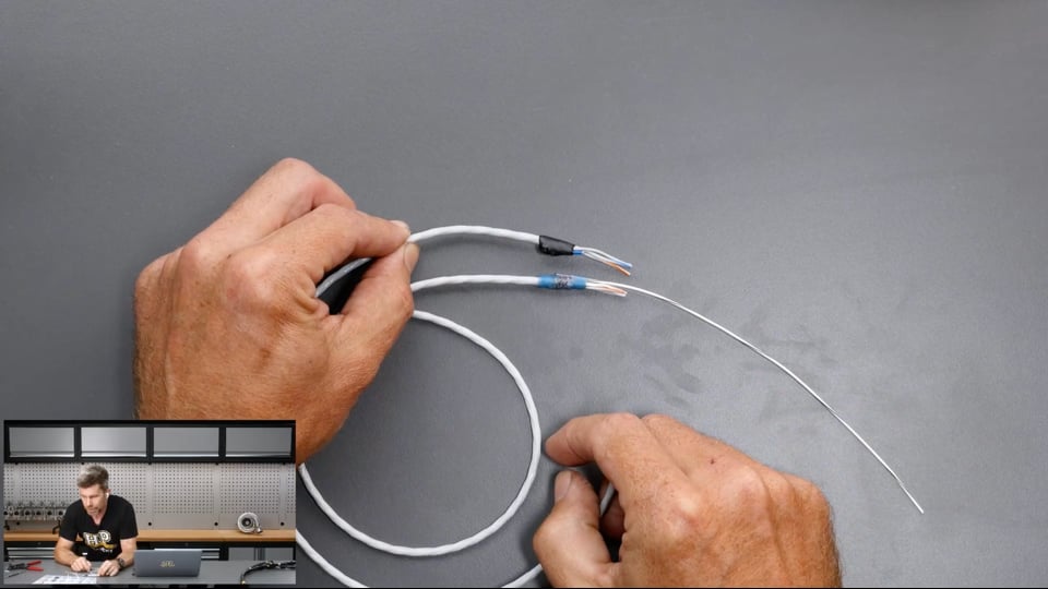
| 17:45 | Alright, enough talk, let's have a look at how we do this and really, no surprises here, it kind of starts out the same way. |
| 17:52 | So let's just straighten our wire back out here. |
| 17:54 | And again we're going to use our razor blade here and just a gentle amount of pressure here to run that around and just basically we want to break through that sheathing. |
| 18:06 | We'll just separate that out by bending it backwards and forward and again just gently run this down the side of our sheath, try only to score the outside of it, we don't need to actually cut through it, it'll be very easy to remove. |
| 18:24 | So we're back to where we were, and what we're going to do here is we're going to basically fold that shielded cable back over itself, so we're going to fold it back down over the sheath itself so we've got a nice solid area there that we can work with. |
| 18:42 | Why we're doing that, there's a couple of ways we could apply this but by doing this, by moving that shield back over the top of the sheath, it's got that nice solid sheath below it and this just helps when combined with our solder sleeve to make sure that everything is going to be nice and solid and we're not going to get that relative movement. |
| 19:04 | So from here, what we can do is just apply our solder sleeve. |
| 19:09 | If you are looking at a solder sleeve on its own, you do need to be aware that one side is larger than the other. |
| 19:15 | It's probably not that easy to see in our overhead shot here but this side of the solder sleeve is very slightly larger in diameter than this side here so that's the one that's going to go over our braid. |
| 19:30 | And we're probably a little bit marginal on size for this one here, I might actualy just jump to a bigger one which has probably gone the other way here. |
| 19:38 | But should be a good enough demonstration anyway. |
| 19:41 | So we get that into location there and what we want to do is make sure that we've got our solder sleeve, our little red band of solder located visibly on the centre of that shielded braid so we know that we're going to get good contact on that when that solder is melted. |
| 19:59 | Now in this case, as you can see I've got there the larger diameter sleeve which already has our shield wire attached to it so nice and easy for doing this. |
| 20:08 | But of course the other option would be simply just like you saw, take another length of wire, strip that down, we only want a short section of exposed conductor there and basically before we heatshrink this down, you can just install that, making sure that the exposed conductor strands align again with our braid and with our little solder sleeve, solder band. |
| 20:31 | Alright so what we'll do is we'll heat up our heat gun here. |
| 20:36 | And what we need to do here is just allow that to recover and you will see that when that starts to recover, the band of solder actually will melt and it goes liquid. |
| 20:49 | And that's going to allow us to know when that's all run out, let's just keep this going here for a second. |
| 21:00 | The red colour basically disappears when that solder has melted. |
| 21:05 | Alright job done there. |
| 21:07 | So we'll get that back under our overhead and we've now got our extra wire coming out for our shield drain. |
| 21:15 | Obviously for our demonstration here, I haven't left much length on these, that's not very realistic but you can kind of still get the sense of what that's going to look like and if we compare that to our first example, you can see that it does remove a little bit of the bulk of using the open barrel splice there so just a slightly neater solution that's going to give you a lower profile finish, particularly if you are doing multiple splices all in the same region. |
| 21:41 | Alrighty, let's have a look at our questions and again if you do have any more questions, please keep them coming. |
| 21:46 | Fred has asked, what would be the maximum or preferrable length of wires not covered by the shield? That's a tough one because ultimately the less wire you've got exposed without the shield the better. |
| 22:02 | Normally realistically you're going to need somewhere in the region of about 30 to 50 mm to actually have something that's workable. |
| 22:11 | What you can get away with though could be considerably longer. |
| 22:15 | I've seen quite a number of ECU manufacturers provide adapter harnesses or maybe not ven ECU manufacturers, aftermarket parts suppliers basically making adapter harnesses for ECUs which are probably between 300 and 500 mm long where no shielded cable is used, it's just simply a jumper wire from one place to another and I've never ever had an issue with any of those so it can be made to work but basically you want to eliminate as much chance of anything going wrong as possible so keep that section of unshielded cable as short as you physically can while still making it easy enough for you to actually work with. |
| 23:00 | 25A Spooner has asked, just placed an order for a Nexus R5 vehicle control unit, I'm curious, what is the best way to manage its sensor grounds? Can all of them be connected to the single pin on the VCU? So the VCU is not an ECU that I have personally wired, VCU and ECU's just confusing to be honest, let's just keep it to ECU for the moment. |
| 23:22 | I can't speak from personal experience and my first advice will be always read the manual. |
| 23:30 | There will be undoubtedly some pretty detailed wiring diagrams from Haltech about how to go about this so I don't want to speak out of turn. |
| 23:38 | What I will say is that it's pretty common for most ECUs with a lot of sensor inputs to provide 2 or 3, maybe more 5 volt sensor supplies and the same amount of sensor 0 volt references. |
| 23:54 | So what I tend to do is try and spread my sensors over the available 5 volt supplies and 0 volts so we're not basically overloading a single sensor ground. |
| 24:07 | Now I say overloading, what you do need to understand is the sensors that we're talking about here, maybe fuel pressure, manifold pressure, throttle position, the actual current draw on these sensors is very very low so we're not going to necessarily exceed the current handling capability of the pin, that's not our issue there but it's always sensible there just to load share as much as we can and spread that load across the sensors. |
| 24:32 | Some ECUs as well where there are multiple 5 volt and sensor 0 volts, you do need to be mindful there may be some strategy where you should be using a particular 5 volt output and sensor 0 volt that are referenced together. |
| 24:46 | Some ECUs don't seem to be so sensitive to that but that's just something I would watch, again sorry I can't be more specific, not an ECU I've wired. |
| 24:53 | Racing's asked, for harness design, do I map my harness starting at the sensors back towards the main or from the main outward? No real right and wrong must dos with this. |
| 25:08 | But generally I would always suggest starting from the ECU or the bulkhead connector and working your way out. |
| 25:16 | That's the natural way that the harness is going to be laid out and it makes sense working that way so if you've taken any of our courses and seen this, Zac demonstrates this using nylon rope which is really easy to get hold of, nice and cheap. |
| 25:29 | Nice thing about nylon rope is you can purchase it in different diameters so you can get something that sort of replicates the diameter of your main harness trunk and then also the smaller sections and then what we can do is basically tape them together at the branch points that you've got. |
| 25:48 | So you can lay that out through the engine bay and get a really good sense of where your harness is going to need to run and make sure all of your lengths for each of the sensors and actuators is correct using that rope. |
| 26:00 | Then basically once you've got your harness designed in rope, take that out and then you can measure it, transfer all those measurements to paper and then actually work from your design document. |
| 26:13 | Chase has asked, is it better to crimp or solder resistors for pull up or pull down. |
| 26:18 | OK so this is another one of those areas where for every rule there is an exception. |
| 26:24 | If I'm doing a pull up or a pull down resistor, that is something I will solder. |
| 26:29 | This is again just about reliability and neatness. |
| 26:34 | I actually might do this as a webinar idea at one point, it's relatively straightforward but what I basically do, when I'm making a pull up resistor or pull down resistor is that I will solder each leg onto a section of 22 gauge wire and then basically bend one leg back on itself and then put the entire section that's soldered including the resistor inside SCL heat shrink and then shrink that down. |
| 27:00 | So that SCL is providing us with that mechanical strain relief, preventing the relative movement of the wire and giving us the reliability from that product. |
| 27:15 | Fred's asked, I haven't seen any reference to shielded wires on the AEM Infinity manual, does sensor ground, would the sensor ground be the best thing, is even the ECU ground good? So typically if you've got an ECU that doesn't have a dedicated shield drain, then sensor ground will be the pin that is used for that, not the ECU power ground so I'd be very surprised if there isn't some reference to that in the Inifinity manual but that is pretty typical. |
| 27:45 | Alright that's all the questions we've got there so we will finish up and as usual if you are watching this in our archive and you've got further questions, please ask those in the forum and I'll be happy to answer them there. |
| 27:56 | Thanks for watching and we'll see you next time. |
Timestamps
0:00 - Introduction
0:35 - What is shielded cable and why do we use it?
1:05 - Typical uses
2:30 - Available in a range of configurations
3:40 - Stripping demo
5:00 - Why we need to terminate it
5:24 - Where to terminate it to
8:15 - Terminating with an open barrel splice + SCL
13:55 - Terminating with a solder sleeve
21:45 - Questions


