304 | Setting Up Steering Wheel Buttons
Summary
Adding driver switches or controls to a steering wheel is common in race applications however this adds some complexity to the wiring, traditionally requiring a complex curly cord between the steering wheel and chassis. A smarter way of adding these inputs is to use a CAN hub which greatly simplifies wiring. In this webinar, we’ll look at how these are configured.
| 00:00 | - Hey team, Andre from High Performance Academy, welcome along to another one of our webinars. |
| 00:03 | And in this webinar we're going to be looking at CAN switchpads and specifically here we're going to be looking around how we can integrate one to simplify our steering wheel button wiring. |
| 00:15 | So I'll show you the steering wheel here of our SR86 and we've got a bit of stuff going on here, we've got controls on the steering wheel for a pit limit, for a push to pass, we've got radio, we can also control dash functionality on the MoTeC C125 dash with a scroll and page change, we've also got an alarm reset. |
| 00:37 | We have got a horn button which is not currently functioning as a horn button. |
| 00:42 | And then we've got two multi position switches here for boost and traction control and launch setup. |
| 00:48 | On the other sied here we've also got a couple of paddles for our paddle shift and the focus of today's lesson is the little Ecumaster CAN keypad. |
| 00:59 | But before we jump into that, I'll just talk a bit about the traditional way of doing that which would be to basically wire everything into a curly cord and these are available pre wired basically or pre made I should say, the curly cords themselves with a various number of conductors. |
| 01:18 | I personally haven't had much success with curly cords, in terms of the larger conductor count, staying curly which obviously is their aim. |
| 01:28 | This one here, and I'll try and get it into shot, I can't unplug it unfortunately at the car end but this is another pre configured one but it's only a 5 or a 6 conductor lay up and it's been really good. |
| 01:43 | I find that the smaller conductor counts generally tend to keep their shape over time but the more, the larger conductor count, 12 + conductors, the ones that have been custom curled, I've found that those tend to loose their curl over time. |
| 01:58 | The other aspect though is just the complexity of wiring everything. |
| 02:01 | So all of those switches will need switches themselves, the digital switches will need a sensor 0 volt and then a digital input to your ECU dash or whatever device you're communicating with. |
| 02:12 | The analog voltage potentiometers, the ones for multi position switches, those will need a 0 volt, a 5 volt supply plus your analog voltage output. |
| 02:21 | So there's a bit going on there despite the fact that you can share the 5 volt with all of your potentiometers and you can share the sensor 0 volt with all of your potentiometers plus digital switches, there's still a bunch of work there to get all of your wiring across the car, to the car where you can actually make use of it. |
| 02:41 | So while yes it can be done with curly cords, we want to look at simpler options and one of those at the high end, the likes of GT3 race cars, they'll do away with the curly cord completely and the likes of Krontec I think off the top of my head it is, make a really nice integrated quick release hub that has an autosport connector, so basically an autosport wiring pass through in the centre of it so that's a nice way of doing it but it is a very expensive way and it creates a bit of complexity around the termination of wiring to that particular unit. |
| 03:18 | However it is a neat way of doing it. |
| 03:20 | There are also some wireless units that are available, I haven't personally tested one of those. |
| 03:29 | I do have my reluctance with that just around the fact that wireless units like that, while I have no doubt the reliability of the higher end units is guaranteed, I always worry a little bit about something that's battery powered, basically you're going to end up with the batteries going flat at the most inopportune time so I don't personally like that idea for that very reason but I know there's plenty of people using them with success, just a personal preference really. |
| 03:57 | Anyway, today what we're talking about is using a CAN switchpad to simplify your wiring and the reason that it simplifies your wiring, yes we do still need a curly cord but instead of 12 or 16 conductors or whatever you may need, it breaks it down to just 4. |
| 04:12 | You can use a CAN high and CAN low, all of the information that's relevant is sent as CAN messages over that CAN bus. |
| 04:20 | And then 12 volts and earth so just 4 conductors are all we need to get between the steering wheel and the car and our job is done. |
| 04:29 | Now there are a variety of manufacturers producing these units so I'm not really focused on any particular brand but of course we are here using the Ecumaster CAN switchpad so that's what I'm going to be describing but essentially for all intents and purposes, everything that the Ecumaster CAN switchpad does, you'll probably find that any other CAN switchpad also does, the principles remain the same. |
| 04:58 | Nice feature with any CAN switchpad is that it allows pretty easy integration with a variety of aftermarket motorsport electronics as long as they either have a pre configured CAN template for the Ecumaster switchpad and I'll admit that is probably a little bit rare but alternatively if they have a user configurable CAN template then we're good to go as long as we understand CAN. |
| 05:25 | If you do want a bit more information on CAN, you can check out, can check out, you see there's a little pun there, unintended, anyway I digress, our CAN decoded course which will go into a lot of detail on how these messages are constructed and how to basically send and receive information over CAN, today will be a high level look at that. |
| 05:45 | So let's just jump into my laptop screen here for a moment and this is all taken from the Ecumaster CAN version 3 switchpad manual. |
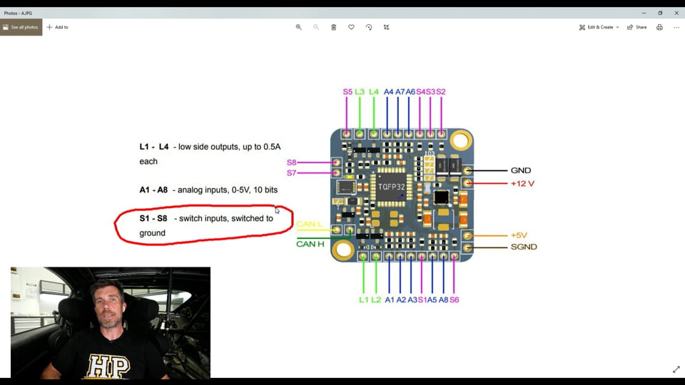
| 05:55 | So I've basically, rather than scrolling through the manual in front of you here, I've just taken the key ones that I wanted to really highlight so this is what the CAN switchpad looks like and this is probably actually a little bit larger than real life, it is incredibly small and again I'll just get it up in front of the camera so you can see it. |
| 06:16 | Yeah this little guy here and really really small so what that means is it's very easy to integrate with just about any steering wheel, or you don't necessarily have to put it in the steering wheel, obviously anywhere you want to integrate multiple switches and simplify the wiring back to your electronic devices. |
| 06:33 | So what we've got here is first of all they have 4 low side outputs that'll support up to half an amp current draw. |
| 06:43 | So you can use these for driver indications, so LEDs for example or warnings, basically anything you want to basically bring to the driver's attention. |
| 06:52 | I'm not using that because all of our driver warnings and indications are done through the MoTeC dash so in our application, not using the low side outputs, you could also use these to switch things on if you wanted, basically your imagination is the limit there. |
| 07:07 | Then we've got 8 analog voltage inputs, these are 0-5 volt analog voltage inputs. |
| 07:14 | So we'd typically be using these for our potentiometers or multi position switches. |
| 07:19 | So in our case as you've seen, we've got two of those. |
| 07:23 | We've used a product that we've sourced from motorsport electronics here in New Zealand and these are actually I think an 11 position switch. |
| 07:31 | And I always find for the likes of traction control, launch control and boost control, the normal 10 or 11 position switches that we usually find just gives us a heap more options that I ever really need. |
| 07:46 | I personally don't ever see the need to have more than maybe 4 positions for any of that. |
| 07:51 | Nice application there with the motorsport electronics switches, it has a little pin that comes in the pack with the switch and basically you can put it in any location. |
| 07:59 | So you can have between 1 or 2 I guess you'd call it, 2 positions up to the full 11 and basically restrict it to what you want. |
| 08:10 | So we've got 0 through to 4 so 5 positions and that's worked really nicely. |
| 08:14 | So that's wired up to our analog voltage inputs and then we have our switched inputs. |
| 08:19 | So we've got S1 through to 8 so again 8 switched or digital inputs so those are for our little buttons there that you've seen on the steering wheel so it's actually a really powerful product. |
| 08:31 | So 8 analog voltage inputs, you could of course use these for switched as well, 8 switched inputs and then those 4 low side drives. |
| 08:39 | Now on top of that we've got a couple of other wiring considerations, we've got our power and ground, so this is coming from the car, 12 volt and ground, that's required to actually power the whole thing up. |
| 08:49 | And then we've got our 5 volt output and our signal ground. |
| 08:53 | So those are going to be wired up to our potentiometers and our switches on the steering wheel. |
| 08:58 | Does get a little bit fiddly splitting these out, particularly the signal ground when you're going to splice that out to potentially in our case, I can't remember, 6 or 7 switches or whatever it is, plus the two potentiometers. |
| 09:10 | But you have to work through that, it's just one of those requirements. |
| 09:13 | And then we've got the analog and switched outputs on each side and then CAN high and CAN low. |
| 09:22 | Does require soldering so this is another thing that's just worth quickly touching on. |
| 09:27 | In most instances, we always recommend where possible, staying away from solder but for every rule there is obviously always an exception and in this case, solder is absolutely the right option. |
| 09:42 | There is a couple of considerations here around why solder works in this application and one of them is because we're soldering to a PC board so basically we can also isolate our wiring so there's no relative movement, that's quite important when we are soldering there, so we do get a really reliable result even though we are resorting to solder there but again when we're working with a PC board, that's basically the situation we'll find ourselves in. |
| 10:06 | Alright so that's they physical wiring there and again I'll just get our steering wheel back into shot, just a couple of considerations here. |
| 10:16 | All our wiring on the back of this is sheathed with DR25 and we can buy little heat shrink boots from Hellermann that can be used to heat shrink over the back of the switches because we're also going to be soldering to the back of those little switches. |
| 10:34 | So those boots again just help isolate relative movement between the wires and the switches which is going to aid our long term reliability, getting the best result possible when we are using that solder and that's really the consideration is always around understanding the potential downsides or pitfalls with solder and going out of our way to make sure that we are mitigating those to the best of our ability. |
| 10:58 | Alright so that's our switchpad physical mounting and wiring, it's pretty straightforward there. |
| 11:05 | Let's just have a quick look at the, again the recommendations for this which is all pretty straightforward here. |
| 11:12 | So we've got the way we would wire a switch here. |
| 11:15 | It switches to ground, so there's an internal pull up resistor there so we want one side of the switch or button that we're using to be wired to their sensor ground and if we, signal ground I think we called it here, yep signal ground there and the other side will be wired to one of these purple switches, S1 through to 8 so that's what our switches look like and the internal pull up resistor inside allows the switch panel to differentiate between the open state and the closed state. |
| 11:45 | 12 volt and ground, yeah nothing really much more to talk about. |
| 11:48 | The CAN high and low, we do need to follow normal protocols with our CAN bus connection which I'll talk a little but more about shortly but basically we need to make sure that that is a twisted pair. |
| 12:01 | Then potentiometer, how that gets wired again pretty self explanatory there. |
| 12:05 | We need the 5 volt and the sensor 0 volt and then the analog voltage input and then if we want to connect a low side drive, again just how we'd switch that so in this instance, used to switch an LED on, alternatively we can use it to switch a relay, remembering that it is limited to a half an amp current draw so if you want to switch on something like a thermofan or a fuel pump, I don't know why you'd use that product for it but obviously it can do it, you'd need to run that through a relay. |
| 12:35 | Alright so just talking a little bit about the CAN bus integration. |
| 12:38 | So again I'm not going too deep into CAN within this but we do need to basically keep the standard protocols for constructing a CAN bus in mind. |
| 12:49 | The key here is what we need to do is make sure that for a longer CAN bus, over about 2 metres in length is generally what's considered a long CAN bus. |
| 12:57 | We want a terminating resistor at both ends, that is nothing more complicated than a 120 ohm resistor at each end of the bus joining between the CAN high and the CAN low. |
| 13:09 | Under 2 metres you can either use two terminating resistors just like this or with shorter buses you can get away with just using a single terminating resistor at one end of the bus. |
| 13:21 | The other thing we want to be mindful of is how far away from the main trunk of the CAN bus we mount our devices because here we've got multiple devices, our SR86 is probably on the more complex side of things, we've got, if I can list them all off, we've got our MoTeC C125, we've got our MoTeC M150 ECU, we've got two PMU16s, we've got a MoTeC lambda to CAN and then we've also got a variety of CAN based sensors including tyre pressure monitoring, brake temperature, we've also got laser ride height that all send data via CAN so the layout of the CAN bus is quite critical, obviously we've also got our Ecumaster switchpad, because if we don't end up designing that CAN bus properly, it can result in communication errors so keeping that in mind, coming back to our diagram here though, this is again from the Ecumaster manual. |
| 14:16 | They're recommending a maximum of 30 cm from the bus, I've always gone off MoTeC's literature, their recommendation is 500 mm, 50 cm from the bus, I've found that to work really well so I mean obviously less is more so just keep these sorts of things in mind with where you're routing the bus and what the run is going to be from that main trunk of the bus out to your different devices. |
| 14:43 | Try and keep with best practices and then you know that you're not going to be introducing a problem that you could have got away with. |
| 14:54 | Even though I've seen some CAN buses that just were constructed like a spaghetti bolognese and they still seem to work. |
| 15:03 | It is quite a resilient communication protocol but again stick with the industry best practice standards and then you really can't go wrong. |
| 15:11 | Why I want to talk about the terminating resistor is that with the design of the steering wheel, usually but not always that's going to end up as one end of the CAN bus. |
| 15:23 | You could make it part of the CAN bus but you would need to run the CAN high and low into the steering wheel and then back out so then you're adding another two wires to your curly cord so kind of defeating some of the benefits of communicating via CAN. |
| 15:38 | So on the back of the switchpad here, we do have a termination resistor, essentially you can solder across that jumper there and this will integrate a built in terminating resistor, meaning that you don't have to do anything more, or of course you can leave that open with no terminating resistor. |
| 15:58 | I only mention it because it is something that's very easy to overlook, if you've got multiple terminating resistors instead of the recommended two, or you don't have one at each end, you can end up with problems with communication which we'd rather not. |
| 16:13 | Alright the other aspect here is setting up the communication because again when you've got multiple devices on a single CAN bus, you do need to make sure that they are receiving and transmitting on independent identifiers at different addresses otherwise everything's going to end up becoming confused and just it's not going to work. |
| 16:39 | The other thing that's really easy to overlook is we want all of our devices communicating at the same speed. |
| 16:45 | So there are 4 little jumpers here, I'm not going to go too far into the details, there's just a simple little grid in the manual you can follow to set the transmission speed that this device works at, in this case we're using 1 MB which seems pretty well standardised across most aftermarket electronics and then the actual address that it will be sending out the data. |
| 17:08 | Alright so that's kind of the hard work done there and I wanted to just go through some of the ways we are using this data. |
| 17:17 | Cause ours is again a little bit complicated, basically one of the nice things with CAN is that the same information is just broadcast out on the network and then any device that is connected to that network can make use of that message if it's required, if not it just ignores it and it goes sailing on past, no big deal. |
| 17:37 | So what we need to do though is understand how the messages are constructed so that we can then decode them where and when we need them. |
| 17:48 | So let's have a quick look at this, again comes from the manual here. |
| 17:52 | So we can see here depending on the way we've got those jumpers arranged, the base identifier is hexadecimal 640, that's what the 0X means at the start of that number. |
| 18:04 | So not a decimal number, it's a hexadecimal number. |
| 18:06 | This for us was problematic because it just so happens that that is one of the standard addresses that the M150 ECU sends out information to be received by the dash so we had to rejig that and I think from memory we ended up with a base address of hexadecimal 702 or something like that, we'll see in a moment but beauty of that is we can change that ID to suit our requirement. |
| 18:31 | So this is really the key elements here of how this is all constructed. |
| 18:37 | So it sends out 3 messages, the first one here is our base ID so in this case if we hadn't changed anything, this would be 640 and it sends out the information we'll have a look at in a second. |
| 18:51 | Then the second message it sends out is on base ID plus 1 so 641, no real rocket science there and then of course 642 for our third message. |
| 19:01 | So if we look at our base ID, our first message that's sent out, we've got 4 of our analog voltage outputs, so these are our potentiometers and these are sent out in a raw millivolt form and they are sent out as 2 bytes so that we can get decent resolution there. |
| 19:20 | The second message just repeats this for analog voltage 5 through to 8 so that's fine. |
| 19:25 | And then we've got the switched inputs here, sorry this one here I think it is, switch mask in byte 4 and that's where our switched inputs are sent out so these are just a single bit that's changing so we can actually fit all of that into a single byte with no problems. |
| 19:43 | And then there's a little bit more information that's coming through that's probably not too relevant to our purposes today. |
| 19:49 | Rotary position is on R1 through to R8 and yeah you can see everything else that is sent there including a heartbeat message which is just a counter that increments every time a message is sent. |
| 20:05 | So that's all the information there and default frequency that that is transmitted at is 20 Hz. |
| 20:11 | Alright so we need to have a look at how we are receiving this information. |
| 20:15 | So let's just power up the car for a moment and what we'll do is we'll start by having a look at a simple function inside the PMU software. |
| 20:25 | So this is our Ecumaster PMU software and if we look at our inputs here, this is where we're receiving the information on a object, message object there, we'll open that up and just see how it's set up. |
| 20:41 | So it's on, CAN bus CAN 2 so all we need to do here is choose the correct CAN bus that is connected to the CAN switchpad, goes without saying really there and as I mentioned, we're not using that standard ID, we are, I was right, it's hexadecimal 702. |
| 20:58 | So nice feature with the Ecumaster PMU is that we can actually see live data on that particular bus, sorry that particular message and if I just OK yeah if we just have a quick look here, I mean it's not going to really mean too much. |
| 21:19 | I'll just get rid of that and we will highlight, I think, can't remember which one it was here, if we look at that, at the moment we've got no data coming through it and if I click on our push to pass, there we go, you can see the value there goes from 00 to 04 so that's just a really nice feature that I've always liked with the Ecumaster PMU16s is just that live CAN capture so you can really see exactly what information is there on the bus. |
| 21:45 | Alright so we'll click OK, so that just sets up the actual message object and then we have to set up individual inputs from that object. |
| 21:51 | So let's have a look here at our radio input. |
| 21:56 | So we'll double click on this. |
| 21:58 | So first of all we have to give it a name so this is our radio switch, so basically I can press a button on the steering wheel and talk to whoever's in the pits as required and all this does is it outputs to basically power up the radio and switch that to transmit. |
| 22:15 | So it's actually a little bit of overkill really for what we're actually achieving but it's how it works. |
| 22:21 | So we select which message object this message will be on which of course is the one we've just looked at, message object 1 and we've got the byte offset. |
| 22:30 | You'll remember that the switch mask was on byte 4 so we're offsetting by 4 bytes and then for this particular information we only want to extract a single bit of data and that is the little tick box there, extract bit field. |
| 22:49 | We're extracting 1 bit and the bit position there is bit 7. |
| 22:53 | We've got some information here, multiplier and diviser which is not really relevant to this because it is just a single bit moving between 0 and 1 so what we can do with the PMU16 though is actually prove that what we've done is working. |
| 23:09 | So if I, no if I press the right button would actually help, I've got the steering wheel upside down so forgive me, we can see here the result. |
| 23:18 | So this is really the key and that should go between 0 and 1, oh if I press the radio button that's actually going to be a huge help. |
| 23:27 | Alright, press the radio button and there we can see our result goes from 0 to 1 and again we can see if we look at bit 4, I can't draw around it at the moment, but if we look at bit 4 there, at the moment it's 00, you can see that goes to 80 so that is how we can extract the individual bit for that particular output and then once we've got that into the PMU16 we can obviously do what we want with it so that's one there. |
| 23:54 | Let's have a look at our rain light just to really reinforce that, so most of this is the same here, we've got the same setup, the same message object and we're still extracting from byte 4. |
| 24:08 | Bit count still 1 and then this time the bit position is 1 and rain light, just check that one. |
| 24:17 | Yeah there we go so we can see again our result is moving between 0 and 1. |
| 24:23 | So reasonably straightforward. |
| 24:25 | Now obviously those are just the switched inputs there, I'm not sending any of the analog voltage potentiometer data into the PMU16 because we simply don't need it. |
| 24:34 | But it's OK, let's have a look at how we can set that up anyway and this time inside the MoTeC C125 dash. |
| 24:42 | This is a good time to mention that if you do have any questions, we'll be stopping for questions very shortly so please feel free to start asking those in the chat and we'll jump into those once we've finished our demonstration here. |
| 24:55 | So what we're going to do and this does look a little bit complex but don't be overwhelmed by it. |
| 25:00 | We're going to come into connections and communications here and we are working here in the C125 on CAN bus 1, don't get confused because in the PMU16 we're on CAN bus 2. |
| 25:13 | We don't have to have the same CAN bus number, it just means that those CAN buses need to be connected to each other. |
| 25:20 | On the PMU16 we've got 2 CAN buses, on the C125 dash we've got 2 CAN buses, on the ECU we've got 3 CAN buses so just really important that all of the data that we want to be communicating here, we want it to be on the same CAN bus. |
| 25:37 | Alright so first of all I'll just point out, our first receive template here, this is just a pre configured one in the C125 which is to receive the general transmit template from the MoTeC M1 ECU. |
| 25:51 | That's call M1 general and you can see there that that is on hexadecimal 640. |
| 25:57 | The only reason I mention that is remember that that was the base address for the CAN switchpad. |
| 26:04 | That's what I said, there was a clash there so we couldn't use it. |
| 26:07 | So come down here to our 2 Ecumaster switch panels, messages and we can see on this one here we've got traction control and launch control coming through and on our switch panel 2, probably been a little bit lazy here, I've called some of these just general purpose so I probably really need to go through and reconfigure what I'm actually calling these but here we have our pit switch, we'll have our paddle up and paddle down for our gear shift, push to pass and off the top of my head, I actually can't remember the other 2, again being lazy and that's a really good way of pointing out that when you are doing this, it's always beneficial, if you're using a general purpose input in the C125 dash, actually go to the trouble of editing it and giving it a useful name because when you come back to some of these setups, particularly the more complex and it's some time in the future, it can be really tricky to remember exactly what you've done, then you have to go through and actually follow the breadcrumb trail and remember what it was you were doing. |
| 27:09 | So if we simply look here though at one of those messages, let's have a look at our gear paddle up switch. |
| 27:17 | So we'll double click on it, so first of all, we've got our address which we've already talked about and then if we go to receive channels, if we go to our gear paddle up and we can see that again we know that for our switches these were all on byte 4 so we've got offset 4 and then we've got our bit mask here, that just extracts that individual bit that we want. |
| 27:40 | This also requires a diviser here so that it actually displays simply a value between 0 and 1. |
| 27:47 | Really important of course to test our work there when we're done so we'll just come through to the monitor and do forgive me, there's a lot of stuff going on in this dash so I'll just go through here and get to the stuff we're interested in. |
| 28:03 | If we come through to our gear paddle switch, so off and on, you can see at the moment that that is sitting in 0 so if I click on the down paddle, you can see it changes from 0 to 1. |
| 28:15 | The one below it for our up paddle, 0 and 1, everything's working quite nicely there. |
| 28:21 | It is really important to have a good understanding of what you're doing there because if you're kind of making it up on the fly and just trying to mess around with numbers until you actually get a valid result come through but you don't fully understand that bit mask and how it works, you can get yourself into a situation where something that is unanticipated can also end up making that message go from 0 to 1 and obviously, particularly for a paddle shift, that's not what you want, we only want that functioning when you really want it. |
| 28:53 | Alright let's come back over to our connections and communications here. |
| 28:56 | I'll just mention there, one of the complexities there with this is that the M1 ECU cannot itself take a message from the Ecumaster CAN switchpad. |
| 29:10 | So what I mean by this, is we're actually using the C125 dash here as a bit of a CAN gateway. |
| 29:16 | The reason for this is the M1 ECU, the CAN template is pretty locked solid and it's only expecting messages in a very specific format which the Ecumaster CAN switchpad doesn't do. |
| 29:28 | So this is where we can get a little bit more tricky and use the C125 dash which is really really flexible in both its receive and its transmit to act as sort of a go between. |
| 29:38 | So basically what I'm doing here is decoding that message that you just saw, the gear shift up and down, we're decoding that in the dash and then we're transmitting that information back out and I think if we come here, yeah we are transmitting that out so that's M1 transmit I've called that template and that's transmitting the information out to the M1 ECU in a format that it's expecting so it can understand. |
| 30:03 | So what we've got there in this little list, we've got our launch control and traction control, those are our multi position switches. |
| 30:10 | Now that's actually launch control and traction control off a single switch there functioning together and the other one is actually boost control. |
| 30:18 | That GP18 where I said I was being a little bit lazy, that is our pit limiter input. |
| 30:22 | Then we've got our boost limit disable so that's our push to pass button, basically it gives us full boost when we're at wide open throttle and touch that button until we back off the throttle and then we've got our 2 gear shift up and down switches. |
| 30:35 | So a little bit more complex than our normal setup but that's again one of the benefits of CAN is that we can be this flexible with it. |
| 30:44 | Let's come back to our CAN switch panel 1 message. |
| 30:47 | So again we'll double click on this. |
| 30:48 | This is base address 700 so sorry our base address was 700 and that was, if we come back to our little thing here, so that is our first base address. |
| 31:02 | So instead of 640 we're 700, not 702 as I mentioned. |
| 31:06 | But before we were looking at our bit mask for our switches, which we can see is down here and that's base address +2 so that's why it is 702 just to clarify, if you're getting a little confused there. |
| 31:19 | Alright so 700, our receive channel's there, so we'll call these traction control and launch control and again this is actually really traction control now and boost control. |
| 31:28 | Just haven't gone through and changed these, bit of a setup that has been changing on the fly. |
| 31:33 | So the information here, remember it's a 0 to 5 volt and the raw value sent through is millivolts. |
| 31:41 | We have got that information, it's really easy, so again if we come back over here, so our first rotary switch is analog voltage 1 and we know that that's 2 bytes starting at byte 0 so let's have a look at what that looks like in the MoTeC. |
| 31:56 | So our offset is 0, meaning that we're starting at the start, 0 and then length of the message is 2 bytes. |
| 32:02 | Now sometimes this is one of the things that you do need to learn with CAN, every manufacturer, works a little bit different in terms of how the back end of their messaging works and what they call things so there's a little bit of working things out there so that we're speaking the same language but relatively straightforward. |
| 32:19 | And then sometimes depending on the scaling you may need to apply a multiplier, a diviser and an adder, in this case it's just sending through a raw value that relates to millivolts so that wasn't necessary. |
| 32:33 | Alright so let's have a look at what that looks like and again if we go to monitor. |
| 32:38 | And we'll scroll down until we've got traction control. |
| 32:47 | Where are we, traction control. |
| 32:56 | Let's come up to launch control is the one I actually want to see. |
| 33:00 | Can't spell. |
| 33:03 | And here we are, alright so at the moment that position there, 2248 millivolts and if I just move the switch we can see that the reading in millivolts changes so the important thing with this is that we're then transmitting that same raw data in terms of millivolts through the M150 ECU so then it's a simple case of decoding that inside of the ECU and turning that into a position in terms of our switch. |
| 33:33 | Alright so hopefully after looking through that you've got a bit of an idea of some of the flexibility that using a CAN switchpad like this does bring us and how much more flexible it is than doing things like this with wiring. |
| 33:49 | And it's not just a case of simplifying that wiring between the steering wheel and the car itself, which obviously I think's a big factor but again it's that flexibility of getting the data onto a CAN bus where it's accessible by multiple devices, just really simplifying your communication to all of those devices. |
| 34:10 | So we'll jump into our questions and see what we've got, not too many at the moment. |
| 34:16 | F40NZ has asked, any experience hooking this module up to a Haltech Nexus R5? No and it may be problematic. |
| 34:26 | The reason I say that is that it does require a flexible CAN bus and I haven't personally used the Nexus R5 at the moment so I don't want to speak out of turn. |
| 34:39 | At least on the earlier generation Elite the CAN bus on the Haltech product was a little bit more locked down in terms of you had to be able to select a pre configured CAN template for the device you wanted to communicate with so I should probably clarify, it isn't a silver bullet for absolutely every application and one of the caveats is there that you will need to be able to read the CAN messages and decode them so it does require a reasonably flexible CAN bus with the device that you are working with so yeah I can't speak or confirm that that is the case with the R5 but I suspect based on my experience with the Elite, unless they have changed that, that would be problematic. |
| 35:22 | I would suggest that you get in touch with Haltech's tech support and just get that absolutely clarified before you go ahead and purchase anything. |
| 35:30 | Alright so obviously I've gone over everyone's head or no one's been watching today because that is the only question that we've got. |
| 35:38 | But for our members, if you do have any further questions after this webinar has aired, please feel free to ask those in the forum and I'll be happy to answer them there. |
| 35:47 | Thanks for joining us and we look forward to seeing you next time. |
| 35:50 | Now for those who are watching on our social media at the moment, if you enjoyed today's lesson then you might be interested in looking at our other webinars in our archive. |
| 36:02 | We've got over 300 hours of existing content. |
| 36:05 | We cover a really diverse range of topics including engine tuning, engine building, we cover wiring as well as race car setup and race driver education. |
| 36:16 | And if you are interested in seeing any of those, our gold membership gives you access to our webinar archive as well as our private member's only forum which is the best place to get trustworthy, reliable answers to your specific automotive performance related questions. |
| 36:32 | You can purchase gold membership for just $19 USD a month however with the purchase of any of our courses, you will get 3 months of complimentary gold membership. |
| 36:43 | You can check all of our courses out at hpacademy.com/courses. |
| 36:47 | One really relevant to today's topic is our CAN bus decoded course so check that out if you are interested in learning more. |
| 36:56 | Again, thanks to everyone who's come along and watched today and we hope we can see you online again in the future, thanks. |
Timestamps
0:00 - Introduction
0:15 - SR86 steering wheel overview
0:59 - Curly cord
2:43 - Autosport connector
3:20 - Wireless unit
3:58 - CAN switch pad
5:46 - Physical construction
9:22 - Requires soldering
10:58 - Connection diagram
12:35 - CAN integration
15:12 - Terminating resistor
16:13 - Setting up CAN communication
17:08 - CAN message construction
20:11 - How the messages are being received
24:25 - Analog input setup
34:10 - Questions


