309 - Quick Lambda | Auto Tune - MoTeC M1
Summary
Dialling in your VE table manually can be a time consuming process but fortunately there are some shortcuts that MoTeC have provided to help fast track this. In this webinar we’ll be looking at how to setup closed loop lambda control, and how to use the Quick Lambda and Lambda Was functions. For this webinar we’ll be using our Nissan SR20VE Turbo engine fitted with a M150 ECU.
| 00:00 | - Hey team, Andre from High Performance Academy here, welcome along to another one of our webinars and this time we're going to be diving into the MoTeC auto tune or quick lambda function as it's referred to. |
| 00:11 | This is a function that I know a lot of MoTeC tuners don't even know exists. |
| 00:17 | It's a quick keyboard shortcut, or actually there's a few of them that we're going to discuss in today's lesson that can really aid or speed up your calibration, particularly if you are starting from scratch and you've got absolutely no volumetric efficiency map in which case it's very possible as you get started dialling that VE table in that you're going to have quite large errors in your air/fuel ratio so yes of course you can tune manually by using the page up and page down keys, manually entering numbers into the VE table but what that does is it takes quite a bit of time so the quick lambda functionality is a really good way of fast tracking that. |
| 00:59 | This can also, the functionality we're going to be talking about can also be used for basically closed loop fuel control. |
| 01:08 | I'm going to dive into that briefly, we've got another webinar that covers closed loop fuel control so for more information you can check that out but we'll go over the basics of that as these sort of work hand in hand as well when we are tuning on the dyno, not just when we get out onto the racetrack or out onto the road and finally we'll look at the lambda was function which is a really quick way of dialling in your calibration based on data logging from the track or from the road. |
| 01:36 | Alright so first of all we'll talk about what we actually need to enable any of these functions and obviously to start with, we're going to need some way of getting lambda information into the MoTeC ECU. |
| 01:50 | Now yes there are a wide variety of lambda controllers out there on the market, MoTeC is pretty particular in the way the M1 works so unfortunately it is relatively locked down unless you want to design your own firmware using Build to MoTeC's product so what most people would be using is the MoTeC LTC or in this case this is an LTCD for dual so this one will have two lambda sensors, perfect for V configuration engines because we can have one per bank of cylinders. |
| 02:23 | This one's set up for the Bosch LSU 4.9 sensor, they are also available to suit the NTK sensor. |
| 02:32 | And I'll just talk a little bit about the differences in those sensors. |
| 02:36 | Particularly if you are running leaded fuels, then I've found the Bosch LSU range of sensors have a relatively short lifespan, particularly when I was running my dyno shop we were going through LSU, initially it was probably 4.2, the older sensor back then, we were going through one of those probably once a month or month every 3 weeks. |
| 03:00 | I have killed a sensor in no more than 15 minutes of running a vehicle on leaded fuel such as BP Racing's C16, Q16. |
| 03:10 | We don't use that so much these days because E85 so much more cost effective and more readily available but it is worth explaining that if you are running on a leaded fuel, it can be a cost saving to initially buy the more expensive NTK sensor. |
| 03:25 | I think I was getting around about 12 months use out of an NTK sensor on our dyno and this was doing a lot of tuning. |
| 03:32 | So anyway, this one is for the Bosch LSU 4.9. |
| 03:40 | Another way you can do this is use the MoTeC PLM, so that's another option and that will give you a visual display of lambda if you want to mount that somewhere in the dash, albeit obviously at a higher price point, because it's a bit more involved in the electronics. |
| 03:56 | So the LTC communicates via CAN. |
| 04:00 | This is an important element, a little bit really outside of our topic for today but I am a big fan, if you've followed us for a fair while you've probably already heard me talk about this, of CAN based wideband controllers. |
| 04:14 | The reason for this is when we are sending the lambda data as a CAN message, the integrity of that data is guaranteed. |
| 04:21 | What I mean is if we're sending a value or the lambda controller is measuring lambda 1.05, well as long as we are decoding that message correctly which is, we either are or we aren't, we are going to get a value of 1.05 read at the ECU or the dash or wherever we are decoding that. |
| 04:39 | On the analog voltage based wideband controllers, which again the M1 is not compatible with so it's a bit of a moot point but I just want to mention this, we're sending out a voltage that may be 0-5 volts for example and it's very very sensitive to ground offsets. |
| 04:55 | What this means is that if we end up with a ground offset, we end up meaning that maybe the controller's trying to send out a value of 2.35 volts but we might end up measuring 2.31 volts at the ECU. |
| 05:08 | And obviously that is an offset of our lambda scale as well as our voltage so can be quite tricky. |
| 05:15 | There are some grounding good practices to help eliminate that but it still is an issue that I see time and time again. |
| 05:21 | These days there's so many CAN based wideband controllers, there's really no good reason not to use one in my experience. |
| 05:30 | Alright so not only have we got the ability to use this quick lambda functionality where we can press a key on the keyboard and basically automatically correct any error in our lambda, the MoTeC ECU also has a really really good closed loop air/fuel ratio control strategy as well. |
| 05:48 | So we can choose to use that or not, if we've got lambda coming into the ECU anyway, I really see no reason why you wouldn't and what I'll do is we'll just get our car powered up, let our little compressor run and we'll head over and we'll have a quick look at some of these elements before I actually start the vehicle. |
| 06:09 | Alright so basically here, I'll just pause our graph, here on the right hand side, we've got two elements which is our exhaust lambda and our fuel mixture aim. |
| 06:19 | So we're always comparing those two, the fuel mixture aim is simply the air/fuel ratio we want the engine to be running and we can find that on the fuel mixture aim worksheet, I'll just click over to that for a moment and this is actually a flex fuel vehicle so this isn't the actual one we're using but for our intents and purposes it's going to be fine. |
| 06:44 | And basically what we've got here is a 3D table, we've got manifold pressure versus our engine RPM, exactly the same as our volumetric efficiency table and at each point we're essentially just stating our air/fuel ratio target in lambda. |
| 06:59 | If you do prefer to work in units of air/fuel ratio rather than lambda, you can absolutely change that as well and we've sort of got a bit of a graphical demonstration of what that looks like so that's where that particular number comes from. |
| 07:13 | And then the yellow trace that we can see here that's moving around, this is our real time air/fuel ratio and this is just a little bit of idling as I shut the vehicle down before this webinar. |
| 07:25 | So we can see how close we are and if I actually click at a point where the engine was running, we're at 2500 RPM on the dyno here, steady state and we can see that while our air/fuel ratio in this case is perfectly matched, the target was 0.95 and our measured air/fuel ratio was 0.95. |
| 07:45 | The way we're achieving this which sort of comes into what we're going to talk about today as well is due to the fact that our closed loop control is actually adding in this case 6.6% fuel. |
| 07:57 | So it's really important when we're looking at our air/fuel ratio vs our target that we also account for any closed loop control if that is active because it can be misleading if we were just to look at our air/fuel ratio plot here on our time graph in isolation, we look at that and go hey you know what, our VE table is absolutely spot on, it's on point, no need to make any changes. |
| 08:21 | The reality is that that particular point that we were operating at, which is this one here, we would actually want to add around about 6-7% to that volumetric efficiency cell in order to get our air/fuel ratio on point, in other words our volumetric efficiency dialled in correctly. |
| 08:41 | So that's pretty critical. |
| 08:44 | Let's have a quick look over at our engine systems workbook and we'll go across to our closed loop fuel worksheet which is this one here. |
| 08:54 | Again I'm not going to dive too much into exactly what's involved here but there are a couple of aspects that are important with our closed loop fuel control. |
| 09:04 | One of these is our closed loop period. |
| 09:07 | So let's just quickly go full screen on this and we'll get rid of our graph for the moment and basically what this does is defines how long the ECU is going to wait after making a change to the fuelling before it samples the exhaust gas again and makes a further change. |
| 09:27 | So basically this is to account for the transport time delay between the combustion event and the air/fuel ratio actually being measured in the exhaust by the lambda sensor. |
| 09:38 | It's going to depend on a range of things, where abouts the lambda sensor is in the exhaust and a big aspect of this is also going to be how, what the engine RPM or load is. |
| 09:49 | So MoTeC have gone and set this up with a 2D table with exhaust mass flow on the horizontal axis. |
| 09:56 | I typically see this as engine RPM but ultimately it is exhaust mass flow we're really interested in, the higher that exhaust mass flow, basically the faster the transit time, or the quicker the transit time is from the combustion chamber to the sensor which means that we can sample and update much faster. |
| 10:16 | So what we can see is that down in the idle areas, or that particular point was 2500 RPM, exhaust mass flow there was 10 grams per second and we've got a 2000 millisecond period so basically it's going to make a change, it's going to wait for 2 seconds and it's going to sample again. |
| 10:35 | It's actually probably a little bit overkill but generally down in the idle region, if we've got a period of less than about 1000, maybe 1500 milliseconds, what we can find is that the system actually will set up and go into an oscillation where our air/fuel ratio starts kind of doing this thing and dancing all around. |
| 10:54 | And that's because it'll make a change because let's say we're lean, so it will make a change and add fuel. |
| 11:01 | Then it'll sample again but the change hasn't actually had a chance to take effect and be measured by the lambda sensor so it'll still measure lean so it's going to add more fuel. |
| 11:11 | Of course finally it does catch up and the air/fuel ratio will go rich but it's going to go richer than our target and basically the whole loop continues. |
| 11:20 | So if you are seeing this oscillation, it is important just to consider what's going on there and it may require some changes to the period table. |
| 11:30 | My light just fell off but I'm just going to assume that that's going to be absolutely fine. |
| 11:35 | At higher exhaust mass flows which really relate to higher RPMs, we can see there that we've dropped that down to 100 milliseconds so we're actually getting 10 updates a second. |
| 11:45 | Whether or not that's too fast, really again it's going to come down to doing some logging and analysis and seeing what's actually going on. |
| 11:54 | The only other point that I'll make here is we've got two parameters here on the left that really are quite important. |
| 12:01 | We've got the ability to control our trim minimum and maximum. |
| 12:06 | And what we want to do with this is going to depend on the specifics of the application. |
| 12:12 | So let's just open one of these. |
| 12:13 | I've got this set up as a 3D table, you could set it up as a 2D table, you could set it up as a single value and what we've got here, I've essentially got manifold pressure vs RPM as our axes but we are defining the minimum and maximum amount of trim that can be applied. |
| 12:30 | Now why this is important is that even with a sophisticated CAN based controller, we do want to be mindful of a sensor failure. |
| 12:40 | CAN based controllers do have diagnostics built in, should communicate to the ECU and basically disable the closed loop control if the sensor is deemed faulty. |
| 12:50 | But if that doesn't happen, we don't want to give the closed loop control strategy a huge amount of power to add or subtract a massive amount of fuel, this could be dangerous, it could result in really poor running so typically what I would do is allow probably about what we've got here, maybe +/- 15-20% down in the idle areas, maybe in the cruise areas and then up in the higher load where we're at full throttle, I might want to, particularly on a turbocharged engine like this, I might want to limit that to maybe -5% and +5% just to make sure if the sensor does go faulty it's not detected, that we're not going to end up with some problems. |
| 13:32 | On the other hand though, while we are setting the car up initially on the dyno, that might not be enough range, +/-5%, it almost certainly isn't going to be if we've got no VE table so it's sensible to start with this table and maybe we would just set it as a single value and maybe start with -25%, maybe even a little bit more and +25%, why that is important is that it gives the closed loop control a lot of authority to get our fuelling right and it can do it reasonably quickly. |
| 14:02 | So if we go into a cell that's unturned and we find that our air/fuel ratio's lean, it's only going to be lean for maybe a few 10ths of a second before that closed loop control comes in and grabs that and starts making corrections so just important to understand the implications of these elements and I definitely wouldn't recommend necessarily leaving that table set up how we've got it right now once we actually get into running the car at the track. |
| 14:30 | OK so that's our closed loop control, we'll come back across to our tuning worksheet, workbook I should say and our fuel worksheet and what we've got here is our volumetric efficiency table. |
| 14:44 | Even on flex fuel the MoTeC M1 uses the same VE table for both pump gas and E85 as we're using it. |
| 14:53 | Essentially the premise here is that the VE of the engine shouldn't be changing based on the fuel properties and there's a few other background calculations irrelevant to our webinar today that MoTeC go through in order to get that correct. |
| 15:07 | So what we've got here is the ability to make a change to each of these individual cells and we're essentially using our air/fuel ratio error in order to help guide us with that which we've kind of already talked about. |
| 15:20 | So there's a couple of ways we can do this. |
| 15:23 | First of all we can manually enter these numbers. |
| 15:27 | So for example, the point that we were looking at here, 40 kPa, 2500 RPM and we can see we've got a value of 70.8. |
| 15:37 | We know that we are on our target but again we know that we've got this 6.6% trim. |
| 15:42 | So how could we correct this? Well what we could do is just sit in that cell and we could push the page up or page down button as it would need to be in order to get it to a point where our closed loop trim is essentially zero or as close to zero as we can get it and that's got that site tuned. |
| 16:00 | The other way we could do it, if we come back to our 70.8, we can use a bit of maths and if you've gone through our EFI Tuning Fundamentals course, I think one of the most important takeaways from that is how to apply a mathematical correction for an error in our air/fuel ratio. |
| 16:18 | And this is essentially what the closed loop trim as well as the quick lambda and lambda was functions are kind of doing in the background anyway. |
| 16:25 | So if we take that equation, basically we take the lambda that we have, we divide it by the lambda that we want and that'll give us a correction factor that we can then apply into our table so let's just bring up a calculator and I'll just quickly show you how that works, even though we don't have that number at the moment. |
| 16:46 | So let's go, let's say we had lambda 1.1 so we start with the lambda that we have, this works for air/fuel ratio as well, doesn't have to be in lambda and then at that point let's say we want lambda 0.95, that means that we need to apply a correction of 1.16, 16% essentially, that's going to correct that particular cell so then what we can do is come in here, let's say that that was the numbers that we had, we would enter a value of 1.16 and then use the little asterisk symbol on our number keypad above 8, enter that and that will make that change for us. |
| 17:27 | So the other way though is with our quick lambda function which is of course the purpose of today. |
| 17:35 | So we can simply press the Q key on the keyboard and that is going to look at the error in our air/fuel ratio is we aren't running closed loop lambda or in this case it will look at the error in our lambda plus the closed loop trims and it will then apply that correction to our cell. |
| 17:53 | Automatically correcting any error that we've got. |
| 17:57 | So that we can demonstrate this I'll just get us up and running and again I do apologise I should say, it is a little bit noisy in this car, I'll do my best, we also get a bit of vibration when we're up and running so I'll just hopefully make this as easy as we can, we are also now just about completely cold. |
| 18:14 | So hopefully I can make all of this work. |
| 18:19 | If we can even get the car running, that would be a great start to our webinar. |
| 18:24 | Maybe our cold start on E85 needs a little bit of work. |
| 18:29 | There we go, much better. |
| 18:31 | Alright so what we'll do is just get ourselves into 5th gear which is 1:1. |
| 18:36 | Then we'll get up and running on the dyno, if I can get it running on the dyno without stalling it. |
| 18:49 | These demonstrations always go perfectly when they're live. |
| 19:03 | OK so at the moment we're just going to have to leave the engine running for a little bit because we are currently sitting at 21° which we can see here so we are a little bit cold at the moment, hasn't really helped, obviously the engine's been sitting here for the whole time that I've been presenting so far so I'll just apply a little bit of load and allow that to come up to temperature. |
| 19:26 | In the meantime what we can see though is our air/fuel ratio data being displayed. |
| 19:31 | Now it's important to mention here, particularly, and this actually is an element of what we need to consider when we are making our tuning changes, we want to ensure that before we actually start tuning our volumetric efficiency table that the engine is up to our normal operating temperature. |
| 19:50 | Otherwise, we're likely to be in cold start enrichment or something of that nature. |
| 19:55 | It's not going to give us a very realistic result so we want to make sure that if our operating temperature's maybe 82°, we want to be at least there or thereabouts and make sure that we do have no additional fuel enrichment. |
| 20:09 | And we'll just, while we're waiting for that to warm up, we'll head back across to our fuel mixture aim and we can see that our fuel mixture aim state is currently coolant temperature. |
| 20:18 | Which means that that's the exact situation we're in. |
| 20:22 | We'll just open that and we'll see that with our coolant enrichment, we have this situation here where at the moment while we're warming up, we're at about 35° and instead of lambda one at cruise, we are targeting at this point 0.95. |
| 20:39 | If you're looking at these values up here above 60° and thinking why on earth would I be targeting lambda 2.0, the way these look up tables work is that the ECU will always use the richest of the tables so essentially once we get to that 60° point, it's going to switch to our normal fuelling. |
| 21:00 | Alright that should give us enough temperature in it to actually demonstrate this situation anyway. |
| 21:06 | So we're sitting here and you can see again just looking at our air/fuel ratio, now that we've got some real live data we can see it is moving around a little bit. |
| 21:14 | This is absolutely typical when we are tuning our fuelling, we're never looking at an absolute fix, rock solid number, it is always moving a little bit. |
| 21:22 | That's absolutely fine. |
| 21:24 | We can see we're on our target but again what's easy to overlook is that our target is being corrected or our fuelling is being corrected by our closed loop trim. |
| 21:34 | Just currently doing about 7 or 8% trim. |
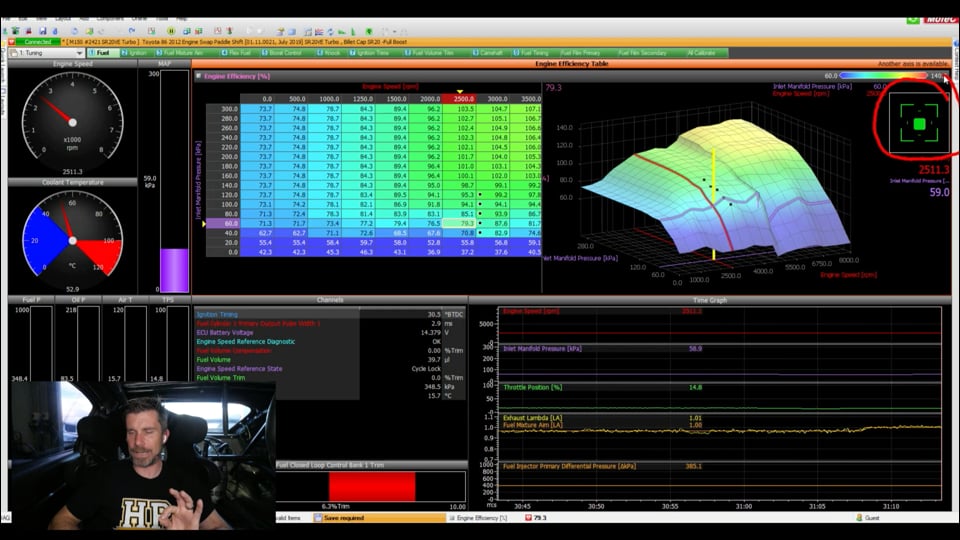
| 21:37 | Another thing that's really important to take note of before we make any tuning changes is this little target that we've got over here on the right hand side. |
| 21:46 | So because the ECU is going to always interpolate from surrounding cells, before we make any changes to the cell, we want to make sure that we're as close to the centre of that cell as we can and as I just let off the throttle, you can see we drop in that cell and it turns red, apply a little bit more throttle, manifold pressure comes up and we can get ourselves really accurately in the centre of the cell. |
| 22:10 | Alright so let's come across to the centre of the cell here and again, you can use all of the options that I've talked about, obviously we want to demonstrate so I'm just going to press the Q key now. |
| 22:19 | Before I do that, the number in that cell at the moment is 79.3%. |
| 22:24 | And you'll see that our trim is sitting at about 6% so I'll press Q. |
| 22:28 | Straight away our closed loop trim zeros, we can see that that trim is being applied, our value in that cell now has been taken to 85.7% and straight away our trim is essentially, well it was sitting really nicely at 0%. |
| 22:44 | Do need to recognise that our coolant temperature is still coming up so this isn't a very good indication of how we should do it. |
| 22:52 | It's exactly what I just told you not to do but do as I say, not as I do. |
| 22:57 | Anyway, we are still within about +/- 1% so we're there or there abouts, pretty good. |
| 23:03 | Now the tuning process, particularly if you follow our Practical Standalone Tuning course, is to start from low RPM and low load and then build up the load by applying more and more throttle and essentially what that means is we're going to move up this 2500 RPM column and as we do this we're going to fill out the additional cells that we can access. |
| 23:25 | Now point to make here is currently we're sitting at 60 kPa. |
| 23:30 | We've tuned that cell, we know the fuelling's good but we had to also add VE to that cell in order to get our fuelling correct. |
| 23:38 | If we look at the number there, 85.7 and then we come up to the next cell above at 80 kPa we can see that that's now 85.1%. |
| 23:48 | It's dropping VE which is probably not very realistic. |
| 23:53 | We're going to expect in most instances as we increase the load our VE will also increase so if I do nothing, what that's going to mean is that as I add throttle and come up to that next site, I'll do exactly that. |
| 24:10 | Little hard to talk here so I'll just pause everything. |
| 24:16 | Yeah little hard to talk at that cell, there's a bit of noise going on but I just paused what was going on there. |
| 24:22 | We can see what happens with our fuelling is initially we sort of go a little bit lean, I've exaggerated that but we ended up going about 4-5% lean and then what's happened is that closed loop trim has kicked in again in order to correct that and by the time I sort of stopped, we're pretty much bang on our target. |
| 24:41 | So closed loop trim there, showing you exactly how that works, doing its job and correcting our error. |
| 24:48 | But the problem is, particularly if we're under a reasonable amount of load, there is a period there where we've gone a little leaner than is ideal. |
| 24:55 | Not an issue at 80 kPa, probably not an issue for us anywhere at 2500 RPM but if we were steady state tuning at 4500, 5000 RPM, we probably don't want to go lean like that. |
| 25:06 | So one of the keys is pre-empting what's going to happen when we move into the next cell. |
| 25:13 | So we could look at this and maybe say well we were let's say 6% lean at 60 kPa so I could add 6% here, 1.06 multiply, that's going to do that, let's just go and see if I was right. |
| 25:33 | OK well we already know what the trim actually should have been, you can see that we've gone -1.7% so we actually went a little bit rich but of course when we're just guessing like this, we always would prefer to start on the side of being a little bit rich and be able to pull fuel out. |
| 25:47 | But there's another function that the MoTeC allows us to use as well which is essentially still based on that lambda was function. |
| 25:56 | We'll get ourselves running here and I'll just undo that change. |
| 26:01 | We'll actually undo, I can't undo that last change. |
| 26:04 | Let's just bring our value back here to 80%. |
| 26:08 | Come back into that cell. |
| 26:09 | So we know that Q quick lambda will tune that particular cell. |
| 26:14 | If we press the W key, and what I want you to do, I'll just delete these marked cells around us, what I want you to do is watch what happens to the surrounding cells when I press the W key. |
| 26:26 | And what the W key does is it kind of takes what it learned from the cell that we've just tuned here, 60 kPa and it's sort of basically copied that out to the other cells above and to the right of it. |
| 26:39 | And basically if we're tuning in that strategy where we're starting at low RPM, working up the load, that's what we're going to be doing. |
| 26:47 | Kind of means that when we get to that next higher load cell we're going to be hopefully there or there abouts. |
| 26:51 | Also as we then move up to our higher RPM column, again we should be hopefully there or thereabouts. |
| 26:57 | So just depends how you want to use that. |
| 26:59 | Personally I typically use the Q key because it can be very very fast. |
| 27:04 | So let's just have a quick look at this now. |
| 27:06 | So what I'm going to do is tune the entire 2500 RPM column, probably only going to be able to get marginally up into the positive boost areas here but just to show you how quickly we can do that, what I'll do is I'll unmark that cell, set it back to where it was, we'll actually start down here at 40 kPa. |
| 27:23 | So the process I use... |
| 27:26 | ...go into the cell, make sure I'm central in the cell, I'll also wait for my closed loop trim to stabilise. |
| 27:33 | That can take a second or so. |
| 27:35 | We can see that's pretty stable at about 8%. |
| 27:37 | Q key, cell is tuned, sometimes we may need to take a couple of bites at this. |
| 27:43 | In this case it's gone to basically a 0% trim, happy with that, all good, OK what we're going to do is key up to the next cell, move up into that using the throttle, central in the cell, allow our trims to stabilise, those are stable, Q key, have a look, make sure we don't need to make a second change, nope we're good, key up, go into our 80 kPa cell. |
| 28:05 | Stabilise our closed loop trims, Q key. |
| 28:21 | OK I stopped talking there because obviously once I get up in the load it became a little bit noisier, a little bit harder to talk so you can see the process though is very fast using that Q key. |
| 28:32 | And the highest we could really get there at the load was around about 110 kPa so couldn't quite get all the way up into our 120 kPa cell. |
| 28:42 | So once we've got that tuned, what we can do is make a decision as to how we want to deal with this. |
| 28:48 | Typically what I'd do is I'd highlight this entire column if I'm starting from scratch, control C, move across to the 3000 RPM column, control V, chances are as we move from 2500 to 3000, all things being equal, I'd probably expect the volumetric efficiency to be increasing so what I might want to do is take a guess that maybe it's going to go up 3%, 1.03 multiply, that's just going to give us a bit of a guess. |
| 29:14 | It might not be quite right but at least when we move up to 3000 RPM, we should be there or there abouts. |
| 29:20 | So I won't continue that process, in fact because we do actually have a tune on this, I will just undo that change. |
| 29:33 | And I'll just shut us down and I'll talk about the element that we're going to have a look at there. |
| 29:39 | Alright just to recap before we do move into how we can use lambda was and how we can use our data during a ramp run, just to recap, the quick lambda's just going to apply the lambda error or our closed loop trim combination to the particular cell that we are operating in. |
| 29:58 | Generally as I say you can expect to get a good result with one change. |
| 30:03 | Sometimes occasionally you might need two or maybe even three changes, three hits on that quick lambda key in order to get on target. |
| 30:11 | A lot of this is going to depend as well on how close to your target you are. |
| 30:15 | If you're a long way off then you could expect to maybe need a couple of iterations to get dialled in but again make sure that you wait for the closed loop trims to stabilise, make sure everything is stable and you are central in that cell, quick touch on that Q key and your job is done. |
| 30:31 | And then at 2500 RPM just to talk about that W function where it's going to copy the VE value up and also out to the next column, whether you want to use that or do this manually is up to you. |
| 30:44 | Like I say at 2500 RPM for me here, I'm not worried if the engine was running lean, it could just about run at the point where it was on a lean misfire. |
| 30:54 | I'm not going to do any damage to the engine but of course that's not going to be the case at 4500 RPM or thereabouts and I'm going to treat that slightly differently. |
| 31:03 | What I will mention there is there's a variety of ways of tuning these tables. |
| 31:08 | And there's no black and white, this is the way you must do it. |
| 31:11 | If I'm tuning a turbocharged engine under steady state at higher RPM and higher load, a technique that I'll use is I'll creep up to the cell I'm interested in, maybe as I go into boost, I might sit down in vacuum and make my changes and then let's say we're tuning our 160 kPa cell. |
| 31:28 | I'll add throttle, get us up to 160 kPa, sit there for long enough to get a snapshot of what the lambda's doing and then I'll back out of it rather than try to make the change steady state. |
| 31:38 | And then I'll make a change to that cell, allow the temperatures to stabilise back in vacuum and then go back and have another look at that cell so we don't need to beat up on the engine too hard. |
| 31:48 | It really all comes down to the type of engine you're tuning, sort of temperatures, the specific power levels you're dealing with etc as to how that's going to work. |
| 31:58 | Alright the other function we're going to talk about is lambda was and this allows us to make changes based on a datalog file. |
| 32:06 | You can do this out on the track, maybe you send the car out around the racetrack and when it comes back, you're having a look at your data and you see consistently that maybe at 5500 RPM and 1 bar of boost you've got an area that's a little bit lean that you'd like to address. |
| 32:22 | Well what you can do there is come back into your map, I can't quite remember the number I said, let's say it was 5500 RPM and 200 kPa 1 bar of boost, let's say we're running at 0.95 there but our target was actually 0.98. |
| 32:39 | What we can do is go to that cell and press the L key for lambda was. |
| 32:43 | That's going to ask you what your exhaust lambda was so again I think as I said, 0.95 so we'll enter that and then it's going to ask you what your aim was, I think I said 0.82, the specifics don't matter, you can probably get the idea. |
| 32:57 | And then it's going to allow us to apply that change, we'll do that and you can see it's made that change there, obviously I'm working with a tuned map, it sticks out like a sore thumb but that's how we can use that lambda was. |
| 33:12 | So it's a really powerful way of quickly making changes based on a data log as opposed to when the car is on the dyno. |
| 33:21 | Last thing I want to do here, quick demonstration for a ramp run and what we can do with that data before we go into our Q&A. |
| 33:28 | So if you've got questions, now is a great time to ask them. |
| 33:31 | Let's get ourselves up and running again. |
| 33:34 | And hopefully this time I won't stall the engine, that would be probably a big help. |
| 33:40 | We'll go back online here. |
| 33:45 | So what I'm going to do is just a quick ramp run here which should be... |
| 33:54 | ...that's interesting. |
| 34:01 | I'm not going to do a ramp run because I cannot see anything on my dyno screen so that's not going to work. |
| 34:10 | I do apologise, that's alright, we can still talk through how we would go about that. |
| 34:16 | Let's just get us shut back down. |
| 34:23 | Alright so, what we'll use for this is a quick, no that's not actually going to work. |
| 34:32 | Let's see if I've got any data here that's going to work. |
| 34:36 | Bear with me for a second. |
| 34:39 | I don't think I do. |
| 34:44 | That is not ideal. |
| 34:47 | OK let's just talk through what we would normally be looking at and basically what we're going to be doing is using our time graph here. |
| 34:54 | So if we had a ramp run on the dyno what we're going to have is still our exhaust lambda versus our fuel mixture aim and what we're going to be doing is wanting to make changes to the VE table based on where abouts we were in the ramp run. |
| 35:11 | So let's say obviously this is at idle but let's say this particular point here, we're at 5500 RPM and 160 kPa and we know that in this case about 4% lean. |
| 35:23 | So what we could do here is use our data, we know where we were in the run so we can go 160 kPa, 5500 RPM. |
| 35:33 | So that's the cell that we would have been accessing. |
| 35:35 | And just as you've seen as I've gone through this, as we're looking at this time graph, if we click anywhere in this, and we go up to our VE table and press the space bar, that'll actually jump to the cell and we sort of see this grey ghost box, I'll just move the cursor away, see this grey ghost box that sort of shows exactly where abouts we were in that particular section of the time graph so that's really important. |
| 36:01 | So any time you're in this time graph, click on a point you're interested in, click in the VE table space bar or any of the tables for that matter and it'll jump to the current active cell so that allows us to be very specific with where we make our changes. |
| 36:16 | So again my theoretical point there was 5500 RPM and 160 kPa and what we can do in here, there's a couple of options, we could use that lambda was function we looked at. |
| 36:27 | Typically for this, I would probably just go ahead and add 4% by typing in 1.04 and then the multiplication symbol and that will make that change. |
| 36:38 | But what we also do want to be very mindful of just before we do this is what our closed loop trim has been doing. |
| 36:46 | Now this was just after startup, our closed loop hadn't cut in so our trim was zero but it's very easy again just to lose track of the fact that just because your exhaust lambda versus your fuel mixture aim is doing one thing, it may be influenced by this closed loop trim so if you're using closed loop then do make sure you take note of that. |
| 37:06 | The other thing which unfortunately I can't show you here is in some instances you may have a situation where the lambda has been leaner than the target. |
| 37:14 | You'll get into a situation where to fix that of course the closed loop is adding fuel and then what will happen there is you might get to a point where there's a cell that's actually a little bit too rich. |
| 37:29 | Because the cell that we move into as we do the ramp run is a bit richer than it should be, plus we've already got a closed loop trim that's positive, we're going to end up with our air/fuel ratio moving significantly rich so it's all about just understanding that combination of what the closed loop trim and our time graph is telling us. |
| 37:51 | Just wondering if I can try and get away with doing a ramp run. |
| 37:57 | Let me just try, it's not ideal, I think I can so let's just try it as talking about it is just not the same so let's give it a crack. |
| 38:05 | What's the worst that could happen? Alright I'll just get back online here. |
| 38:20 | So that we've actually got some data to look at. |
| 38:25 | I suspect we're not going to be able to actually watch the dyno run but that's OK, let's just get ourselves underway and we'll see how we go here. |
| 38:33 | I just to need to wait for our closed loop trim to kick back in here so I'll actually just come back off because if we don't have our closed loop trim working during this, again that's probably going to be a pretty useless display so I do apologise for the fact that this hasn't been so smooth but sometimes when we do these live demonstrations here on the dyno, things do not always quite pan out exactly how you'd expect. |
| 38:57 | We've got a bit of a graphics issue with the dyno that means I'm really struggling to see what is actually on that dyno screen. |
| 39:05 | Alright so we've got our engine up and running and our close loop trim has just kicked back in so let's just get this dyno run underway now. |
| 39:33 | Alright we got there in the end, just allow everything to stop. |
| 39:39 | I can't even tell you how much power that made which is a little bit disappointing but that's OK. |
| 39:44 | Alright we'll shut the engine down and we'll have a look at our dyno graph here, sorry our graph inside our software. |
| 39:54 | And what we've got is our time graph. |
| 39:58 | I'll just move across a little bit, we can see that our peak boost here was 190 kPa, 90 kPa of positive boost so we can sort of see what our air/fuel ratio target does, it starts at 0.95 which is our orange of course. |
| 40:11 | As we sort of start getting up into boost, we sort of see that it tracks down richer and then through the entire ramp run, once we're at full boost, we're targeting 0.80 lambda. |
| 40:23 | But what we can see is if we're just looking purely at this graph, looks lovely, it looks like I've done a really good job here and our air/fuel ratio is tracking that target perfectly. |
| 40:33 | On the other hand we can see from our closed loop trim that that is not the case and as I click through this, 7.5% trim there, 7.3, 11, 6.9, 7.7, so yeah it's pretty ugly really, we've actually got a pretty significant trim basically the whole way through this. |
| 40:53 | So looking at this point here though, this is probably a pretty good place to, let's try right here, this is a pretty good place to make this change so what we can see here and I am splitting hairs because it's not too bad. |
| 41:06 | We can see that our actual fuel mixture aim is 0.82, our target is 0.81 so we're still a little bit leaner than our target anyway and that is with 10% being added so let's jump up, now I can actually show you live. |
| 41:20 | I'll click on our VE table, press the space bar, jumps to that cell and I'll just go full screen on it. |
| 41:25 | We are right at 8000 RPM which is the end of our graph here. |
| 41:28 | And we can see that we're actually targeting between 200 kPa and 180 kPa, of course we're at 190 kPa so this is the perfect storm of what not to do. |
| 41:40 | What I'd do in this situation is make this change to both the 180 and 200 kPa cells and realistically when I am tuning it I always try and make my ramp runs with the boost target right in the middle of one of these rows at least initially so I can fill out that row. |
| 41:55 | But what I'd want to do here is just take note of the fact that just adding a 10% trim is only going to get us to this situation, it's pretty good, let's be honest, we're about 1% out anyway but if we want to try and get that in one crack what we can do is basically highlight both cells, again the 200 and the 180 kPa and in this case the closed loop trim's adding 10% but we're still 1% out so 1.11, 11%, multiply, job done. |
| 42:25 | We run it again and we'll probably find that we are bang on the money. |
| 42:29 | Also just mention here, what is acceptable, what's expected, what's realistic, the closed loop trim is there for a reason and you're never going to get an air/fuel ratio that is always every ramp run, out on the road, out on the race track, always bang on the money with absolutely 0 closed loop trim so if your closed loop trim's within about +/- a couple of percent, you're doing a pretty good job, don't try beating yourself up to get perfection because it is just futile. |
| 42:56 | Alright bit of a messy demonstration but we did get there in the end. |
| 43:00 | Let's jump across to our questions, if you've got more, please ask them now and we'll see what we've got. |
| 43:08 | Manitou Black's asked, are Bosch LSU 4.9 sensors reliable for use pre turbo and for individual λ? No, is the answer. |
| 43:18 | They really aren't designed for the heat or the pressure for that matter that you'll see pre turbo. |
| 43:25 | That being said, we do have pre turbo lambda sensors on this particular car and they are LSU 4.9 sensors. |
| 43:33 | Generally I find that they will last around about a season of racing. |
| 43:38 | It's going to totally depend on the particular conditions they're running in as well as the application as to how long that sensor's going to last, so I can't say that's going to be always the case. |
| 43:51 | One big tip, and this is for sensor life as well as not disrupting the flow too much, if you are mounting pre turbo sensors, there are some special bungs that mount them out of the exhaust manifold just a bit and and let's just come back to my laptop screen for a moment. |
| 44:07 | 'Cause I do have this shown here, don't know why I used an arrow, let's just try that again. |
| 44:14 | And the extended sensor bung that you can see there in the number 1 exhaust runner, that's what I'm talking about, sort of a heat sink element but it also moves the sensor head basically to parallel with the wall of the exhaust manifold so that's a big aid in sensor life there. |
| 44:31 | Now there is a particular Bosch sensor that they have brought out for pre turbo applications. |
| 44:38 | And I've got one sitting on the bench, haven't actually had a chance yet to test it but I believe it does need a specific controller to work with, I don't think they're backwards compatible with an LSU 4.9 controller. |
| 44:51 | So can't give you too much more information about that here because I can't remember the specifics of the sensor. |
| 44:57 | Alright we'll jump back into our questions. |
| 44:59 | Another one from Manitou Black, are serial connected lambda controllers such as Innovate LC-2 as reliable as CAN systems or do they also suffer from ground loops or other issues? No they LC-2 or LM-2 that uses a serial communication, that, it's kind of like CAN in that the integrity of the data is guaranteed. |
| 45:19 | I have had no end of trouble with reliability particularly with my LM-2 and the LC-2 would be the same, communication to the VCM suite scanner which is for HP Tuners software. |
| 45:36 | There is an ability to bring that straight into the scanner software, it's great when it works but usually I find it quite hit and miss with how easy it is to get that data in so I actually switched to an AEM X series CAN based wideband controller that puts the CAN data straight onto the CAN bus into the OBD2 port, that OBD2 passthrough, cannot fault it, it's been really great and bulletproof getting that data into VCM Scanner. |
| 46:10 | Max has asked, I would really like to see boost actuated normal output duty cycle from a full power run. |
| 46:15 | I’m having trouble controlling boost on my personal setup and would love to see your boost duty cycle data log. |
| 46:21 | It's a little off track for our webinar Max and I don't normally do this but let's just jump across and I will show you. |
| 46:28 | I'm going to add the caveat here, this is going to be an absolute mess, I haven't actually looked at this. |
| 46:34 | The reason I say that is just before this webinar, we were doing some turbo testing development and prior to this webinar I had just changed wastegate spring, the only tuning I'd done on that wastegate spring was at 1.8 bar. |
| 46:48 | So that little ramp run test that we just did is not going to be representative but let's quickly jump across to our boost control and just see how ugly that is. |
| 46:56 | We'll go F6 on our boost control. |
| 46:59 | So what we've got here is two elements, we've got our boost control feed forward. |
| 47:04 | Which is the number that's coming from our base duty cycle table and then the yellow value is the actual duty cycle that's being output to the wastegate solenoid. |
| 47:14 | What you can see is actually it looks reasonably good, not quite perfect, our blue line here is our boost target and what we can see here is at the start we've got this discrepancy here, this error. |
| 47:29 | That's because of course the feed forward value was too low. |
| 47:32 | The closed loop control's added to it, it's gone up here to 34% from my starting feed forward, absolute guess prior to this webinar of 15% but it hasn't quite managed to get there and as we sort of go up through the rev range, it gets closer and closer but not there. |
| 47:47 | So what this means is that I just need to go back into the feed forward table and adjust those numbers to get our targets basically where we want. |
| 47:56 | And ideally what we should see here on the dyno is our feed forward and our boost control should be within a couple of percent of each other. |
| 48:03 | Basically that feed forward is the open loop duty cycle, the closer we can get that to our target, the less work the closed loop system has to do so again a little bit off topic but seeing as I've got that data here, pretty easy to show you. |
| 48:15 | I'll just quickly head back and see if we've got anything else before we finish off. |
| 48:20 | And it looks we haven't so that's the end of our questions. |
| 48:23 | As usual, for our HPA members, if you've got questions, following this webinar please ask them in the forum and I'll be happy to answer them there, thanks for watching and I'll see you all next time. |
| 48:34 | For those who are watching today on our social media, if you aren't an HPA member, this is just some insight into what we put on every two weeks for our HPA gold members. |
| 48:43 | Our gold members get to review these webinars in our archive, we've got over 300 hours of existing content in there, covering a massive range of topics on engine tuning, building, wiring, race car driving, race car setup and development and data analysis just to name a few. |
| 49:01 | You also, as a gold member, get access to our private member's only forum which is the best place to get trustworthy reliable answers to your specific questions. |
| 49:09 | You can purchase gold membership on our website for just $19 USD a month but pro tip here, if you purchase any of our courses, you're going to get 3 months of free gold membership. |
| 49:19 | You'll find a full list of our courses at hpacademy.com/courses. |
| 49:23 | Alright thanks again for watching and hopefully we can see you online again soon. |


