310 | How To Use An Oscilloscope
Summary
With many of the more complex signals we see in our ECUs, an oscilloscope is an essential tool. In this webinar we’ll take a look at how to use an oscilloscope to view some common signals.
| 00:00 | - Hey team, Andre from High Performance Academy, welcome along to another one of our webinars and in this webinar, we're going to be diving into some of the basics of an oscilloscope. |
| 00:08 | What an oscilloscope is, why we need one or may need one and how you can go about using an oscilloscope to look at some of the basic signals in your ECU setup. |
| 00:20 | Now this is a topic that I know scares off a lot of people, particularly if you've had absolutely no involvement in electronics. |
| 00:28 | An oscilloscope does on face value seem pretty scary and you're probably more used to seeing oscilloscopes that look a little bit like the one I've got up on my laptop screen at the moment. |
| 00:40 | I had labs full of these when I was going through university and before I actually jumped in and started learning how to use one, they on face value do seem really daunting, particularly when you can see we've got dozens of little buttons and knobs and if you don't know what you're doing with all of these, it can be really hard to try and figure them out. |
| 01:02 | These days, or the other aspects with these oscilloscopes as well is that a conventional oscilloscope like the one that we just looked at can be pretty expensive, often running to thousands of dollars. |
| 01:13 | As with everything as time's gone on and technology has marched along, we are now finding that there's much more cost effective options. |
| 01:21 | So the one that I'm going to show you today is the PicoScope, I'll just get that in view there. |
| 01:28 | So this is a PicoScope 2000 series, it's a dual channel oscilloscope. |
| 01:32 | This I think is around about $300 USD and for our purposes for the aftermarket automotive industry, that's more than enough. |
| 01:42 | There is a wide range that PicoScope make depending on your actual requirements but in most instances a good basic two channel oscilloscope is going to be more than sufficient for what we're typically doing. |
| 01:58 | So let's just roll back a little bit and find out why we need an oscilloscope in the first place. |
| 02:03 | And if you are tuning engines with factory or aftermarket engine management systems, the theory is that the car comes in, we put it on the dyno, we tune it and it goes out the door. |
| 02:14 | And in my experience over 20 odd years now, I think that probably happens in about 1 out of every 4 or 5 cars that I tuned. |
| 02:24 | The rest will have some kind of issue and maybe it's a mechanical fault but quite often the issues that we come across actually involve the wiring or electronics. |
| 02:33 | Now this might be a wiring fault where there's an issue with the wiring harness or something has a ground problem but it can also be a sensor issue as well and this is where the scope can come in handy to actually see visualised exactly what's going on. |
| 02:51 | The other aspect where a scope is really useful is when we're getting a freshly installed ECU up and running for the first time and trying to get the reference or engine speed and position sensors configured in the ECU correctly so we know exactly what's going on, what those signals look like and we can define those in the ECU correctly. |
| 03:12 | So that's where the scope can come in handy, I'll talk about some of the other applications where they come in as well but you might at this stage be wondering well why can't we just use a conventional multi meter or digital voltmeter as they're often referred to as well. |
| 03:26 | This is probably one of the most commonly used tools in my electrical toolbox and they are great for a wide range of fault finding and diagnostics but they do have their limitations. |
| 03:40 | The problem with the voltmeter is that it's great for measuring a steady state voltage. |
| 03:45 | So if we put the two ends of our voltmeter on the positive and negative terminals of our battery for example we're going to probably measure somewhere around about 12 volts and we'll see that up on the screen, happy days so that's really useful. |
| 03:58 | Another application where the voltmeter comes in handy, again with our fault finding, making sure that we have got the likes of a 5 volt regulated supply to our sensors and a sensor 0 volt. |
| 04:10 | Again these are steady state voltages, they don't change or don't change dramatically or shouldn't change with relation to time. |
| 04:17 | However where they do fall over is when we're trying to look at a signal that does change rapidly with time and the voltmeter just can't really help us with that. |
| 04:28 | So I'll just move this out of the way and I'll just bring over a drawing. |
| 04:32 | This is actually a very particular drawing that I'm going to have a look at again in a little bit more detail. |
| 04:38 | But if we look at this here and what we've got here on our vertical axis is voltage and then on our horizontal axis we've got time. |
| 04:47 | What we can see is that voltage is changing and particularly, obviously we've got no time base here to talk about but we can see this little spike here, that's happening really really quickly. |
| 04:56 | Our digital voltmeter can't help us with this, we're not going to be able to actually view and understand that signal. |
| 05:04 | And that's where we need something that can sample the voltage at a high frequency and then give us a visual indication of what that voltage is. |
| 05:13 | And that's where our scope comes in. |
| 05:18 | So what can we test with an oscilloscope and where would we most likely use it? So there are a variety of tasks we can do with the oscilloscope. |
| 05:29 | The most common, probably in my experience would be the reference and sync inputs, the engine speed and synchronisation inputs which I've already mentioned there so getting a visualisation of those. |
| 05:40 | One of the other issues we have with our engine speed and position signals is when we don't have them aligned correctly. |
| 05:48 | And this allow us to visualise both signals together, provided that we have a 2 channel or more oscilloscope we can look at our engine speed in relation to our engine position sensors and make sure that we haven't got the rising and falling edges crossing over or something like that. |
| 06:04 | Obviously not something we should have on a production engine but it is something that we see regularly when engines have aftermarket trigger systems installed on them so we really want to see what's going on there because if we're seeing that engine position signal cross over a tooth on the engine speed, or it's right on the edge, this can confuse the ECU and that causes all sorts of running issues. |
| 06:29 | The other aspect is the signals that go to the likes of our ignition coils and our injectors. |
| 06:35 | These are also high frequency signals that are square wave in those instances and again we're not going to be able to measure those with our voltmeter but we can view those with our oscilloscope. |
| 06:47 | We can also get into the weeds with some of the details such as actually defining what the dwell time for your coils are as well. |
| 06:55 | So there's a lot that we can do with the scope but I'm going to keep this relatively low level and stick to the basics because as I've said, over the time I've been in the industry the reference and synchronisation inputs really are the most common ones that we do need to check. |
| 07:10 | Now ECU manufacturers know this as well and they're trying to make our lives easier so I'd say over the years I've been involved with tuning the requirements for an oscilloscope have become less because now a lot of aftermarket ECU manufacturers actually include a built in scope function. |
| 07:30 | Sometimes it's fairly basic and limited, others are quite sophisticated and really do away with the need for a scope altogether but what I'm going to do is quickly talk though the system that I've got set up here on our bench and what we're actually looking at so I've got a couple of products here. |
| 07:48 | The first, we'll just bring this into our overhead shot here, we've got our Link G4+ Fury. |
| 07:54 | So this is our test bench ECU, we use this predominantly actually for generating signals and engine RPM for the likes of our dash displays when we're doing giveaways and things like that so we can video and photograph those. |
| 08:10 | Now connected to this, so we've actually got something going on, is an AutoSim simulator. |
| 08:16 | So this allows us to basically simulate trigger inputs as well as engine temperature, air temperature, throttle position, manifold pressure, etc. |
| 08:28 | So let's just have a quick look and I'll just bring up our AutoSim software. |
| 08:36 | Let's have a look at our AutoSim here. |
| 08:39 | Just have a look at what I've got running. |
| 08:42 | So we can see here we've got a RPM gauge and we're chugging along here at 5000 RPM so all that's doing is generating an RPM signal that should be 5000. |
| 08:54 | The key point here is the trigger pattern and it is greyed out because I've got the sim up and running but that is the GM 60-2 trigger pattern. |
| 09:03 | Alright so let's head across to our Link G4+ ECU. |
| 09:09 | We can see our trigger mode there is Chev LS2/LS7 and we can see that the RPM is in fact sitting at 5014 RPM. |
| 09:20 | Always a bit weird when you see this on a simulator because as you can see, we're just sitting absolutely dead stationary in a single cell which literally never happens. |
| 09:30 | But at this stage the two signals are matching, the RPM signal from the simulator is matching obviously what the ECU is picking up as well. |
| 09:39 | Now what we can also do is if we click on our R key which brings up our run time values, what we can do is have a quick look at our signal. |
| 09:51 | So this is always a key thing to have a look at here, in the Link ECU particularly but every ECU has this, when we are trying to get an engine up and running, making sure that we have a valid trigger signal. |
| 10:02 | So the way this works with the Link G4, G4+ ECUs is that the trig 1 and trig 2, when the ECU isn't running, the engine isn't running, those will show no, let's actually just do exactly that, I'll just drag that out of the way, we'll bring our simulator up and we'll stop it. |
| 10:19 | Alright, there we go so we can see this is with everything basically disabled, it's not running, we've got no. |
| 10:26 | So as soon as we start it, and obviously here we're not going to crank, it's just going to go directly to 5000 RPM but traditionally if we were just cranking the engine, what we would see is that one of these signals, trig 1, which is our reference would initially go green, that means it's getting an engine speed signal. |
| 10:41 | Then once it's gone through a full engine cycle and it's synchronised and it knows where it is in the engine cycle, the trig 2 signal will also go green and show yes and while we're cranking, it's not uncommon to see this trig 1 error counter increment. |
| 10:57 | I've got it tapped out here at 255 which is the maximum value, doesn't really matter, I was just doing some testing before this webinar with an incorrect trigger mode but let's just get ourselves back up and running, we'll click start here, obviously straight away we jump up to 5000 RPM and we're good to go. |
| 11:13 | So what we'd be looking for here, whilst the engine is running, is that our trig 1 error counter is not incrementing. |
| 11:20 | If we're cranking we can't get the engine to run we'd also be looking at that same element there. |
| 11:25 | Is our trig 1 error counter continuing to increment? Essentially once the engine has reached a steady cranking speed, that should not increment anymore. |
| 11:33 | Alright we'll just drop our RPM back down because we probably wouldn't be doing this test at 5000 RPM. |
| 11:39 | So I just want to show you what we can do often with an aftermarket ECU now with a built in scope function, so we'll go up to ECU controls here and we'll come down to trigger scope. |
| 11:51 | And basically this is the ECU's built in oscilloscope and it's going to look very much like the PicoScope that we'll have a look at in a moment, but we've got all the same functionality here. |
| 12:03 | We can set our trig 1 and trig 2 voltage per division and we can also set the time per division. |
| 12:10 | So voltage per division, that basically references the vertical axis here, the voltage for each of the increments and the time obviously is our horizontal axis down here. |
| 12:23 | So what we can see here, our trig 2 and our trig 1 basically gives us our trigger pattern here and we can make sure that we're first of all getting a valid signal. |
| 12:34 | We can also use the voltage per division to help us define the triggering threshold for a magnetic sensor as well so we're actually seeing how that voltage changes as the RPM changes. |
| 12:50 | So quite useful but what we can see here is that the signal is sort of a bit of a saw tooth and that's not very accurate so that's not what it's actually going to look like when we look at it on the PicoScope and that's because this is a dumbed down system, it's only giving us just the information we need and it's not really a true representation of what that signal actually looks like. |
| 13:14 | Alright so now we've seen what everything looks like on the built in scope function on the Link ECU, we'll talk about the PicoScope and how we can use that. |
| 13:22 | So what I'm going to have to do here is just unplug our Link G4+. |
| 13:28 | Don't really need that for the rest of our test here, and we'll get our PicoScope plugged in and we'll head over to our PicoScope software. |
| 13:37 | At this stage I haven't got anything connected to the PicoScope so we're not actually going to see anything here but essentially it gives us the same display as a conventional oscilloscope but built into our laptop here and obviously as I mentioned at a much lower cost. |
| 13:55 | So at the moment we can see we've got a red line here and we've got a blue line. |
| 13:59 | These represent, the blue line there is our channel A and our red line is channel B. |
| 14:06 | And if you are buying a scope, really as I mentioned, two channel is an absolute bare minimum because we are so often going to want to view two of these channels at the same time. |
| 14:17 | So on the left hand side here we've got our voltage axis, you can see obviously it's in blue, representing our channel A and on the opposite side over here we've got the same for our channel B. |
| 14:30 | So we've got the ability to control the axis as well so for example here we can see that our channel A voltage axis is spanning +/- 10 volts. |
| 14:42 | We've got exactly the same for our channel B but you can click on the little down arrow there and you can set this up to whatever you want in order to basically give you a good range so you can see the signal nice and cleanly and understand what we're actually looking at, we'll leave that there for the moment. |
| 15:03 | Then on the horizontal axis down the bottom we have our time and it's really important again with our time just to make sure that we've got a suitable time per division set up so that we can actually see the signal that we're interested in. |
| 15:18 | That is controlled here, we can see that at the moment this is set to 2 milliseconds per division so what that means is between two of these lines, there and there, there's a timeframe of 2 milliseconds. |
| 15:32 | And this is really the important part with the oscilloscope, like I mentioned with the digital voltmeter, we can't do a good job of understanding what is actually happening to a voltage relative to time, with these signals that are changing very quickly. |
| 15:48 | So this is basically going to trace out the voltage as it changes with time. |
| 15:53 | Another factor that comes into this is the sample rate or number of samples. |
| 15:57 | So we can control that here and at the moment we're looking at 1 million samples per second. |
| 16:03 | Now we'll talk a little bit more about the samples per second shortly. |
| 16:09 | And the importance of that and how that can affect the completed signal that we are going to be looking at. |
| 16:15 | Alright so obviously at the moment we've got really nothing going on here but let's actually start by looking at a signal and get something into the PicoScope so we really need to understand how we're going to do that. |
| 16:28 | And this can be a little bit challenging. |
| 16:30 | So let's just head back across to our photos here and before we started, I just took a shot, a photo here of the engine speed sensor for the Toyota 3UZFE that's in our FJ40. |
| 16:44 | So this is our sensor, we can see that it's got a plastic body on it and it's a 2 pin connector, it's a magnetic sensor so that's why it's got two pins. |
| 16:56 | So we've got the option of where we're going to break into this. |
| 16:59 | Typically for simplicity, I would recommend doing this at the ECU header plug rather that directly at the sensor. |
| 17:07 | That's not particularly helpful, just make sure that that actually is going to charge and not go flat. |
| 17:12 | We're back in the game. |
| 17:14 | Yeah I would recommend doing this at the ECU header plug because if we do it at the engine which we absolutely could, we're going to need to basically extend our wiring for our oscilloscope probes out into the engine bay, generally we might have a situation as well where our engine speed and position sensors or our engine speed position and cam position sensors are not located physically right next to each other on the engine but if we do this at the ECU header plug, we're only talking about small distances. |
| 17:43 | So the next obvious question is how do we actually break into and get that signal out of the ECU header plug? There's a variety of ways of doing this and one of the simplest that I like to use is just to make up some jumper wires so let's just get this under our overhead here and this one here, I've just made up, obviously has a male pin on both sides. |
| 18:07 | Depending what you're trying to do here, particularly with the AMP Superseal connectors, what I quite often do is make up these jumpers with a male on one side and a female on the other and then what we can do is actually extract our trigger wires out of the AMP Superseal connector, put our little jumper wire in between and then that gives us something exposed that we can actually hook our probe onto. |
| 18:30 | Basically it's just going to depend on the ECU header plug that you're working with and basically what is physically possible. |
| 18:37 | Don't really want to be cutting through the insulation on our wires and accessing them in that way, that's definitely not something I would recommend doing, it's always best to actually extract the terminal out of the header plug and then go about it that way. |
| 18:51 | It's only going to be temporary and then you can revert everything to how it was. |
| 18:55 | Now what do we actually need to get access to? So for our trigger signals for example, we need to get access to our trigger 1 and our trigger 2, our engine speed and position but they also have a 0 volt reference so we need to hook into that, so we've got 3 locations that we're going to be connecting to. |
| 19:13 | So what I'm going to do here, we, for our test do not actually need the Link ECU running so what I'm going to do is just unplug the ECU and I'll show you what I'm going to do with our header plug so let's just go to our overhead shot here and our trig 1 and trig 2 are on these two pins right here. |
| 19:38 | So that gives me access to those and then I do have my third pin here. |
| 19:45 | We also have a sensor 0 volt which is in this location right here. |
| 19:51 | OK so not very practical or realistic because obviously I'm not going to be plugging this back into the ECU but as I've said, if you extract those three conductors out of the back of the AMP Superseal connector, you can then jumper them in the way I've just described and get access to everything. |
| 20:07 | One thing to be mindful of of course, we do need to make sure that nothing here is going to short out against another wire. |
| 20:14 | I mean with our engine speed and position sensors, it's not so much a risk of damaging anything but of course that in and of itself is going to introduce problems with the running of the vehicle, that is exactly what we're probably trying to diagnose. |
| 20:30 | So what we're going to do is connect our probes up now. |
| 20:35 | So what I'll do is I'll just get one of our probes insight here with our overhead and have a quick look at it. |
| 20:42 | So this is a pretty conventional oscilloscope probe, they do come in a variety of different styles but for a basic oscilloscope this is probably there or there abouts what you're going to be dealing with and what we've got is at the end, there's nothing visible at the moment but if we just pull back on the probe we can see that that exposes a little hook. |
| 21:00 | And that's basically what we're going to be hooking onto our signal. |
| 21:05 | They also have a ground probe or a ground clamp as well so that's going to go onto our ground terminal. |
| 21:13 | Another thing just to be mindful of is that some of these probes, like this one here, will have a built in multiplier or a potential to have a multiplier. |
| 21:24 | So probably a little hard to read here but in this position, this little red switch here is in the 1x, if we move it over here it's going to be a 10x multiplier so really important to understand that because if you've got this style of probe and it's in the 10x multiplier, the reading you're going to get, understandably on the scope is going to be multiplied and if you don't know that, it's going to be basically be a little bit hard to figure out what's going on. |
| 21:49 | Right so what I'll do, try and do this under the overhead camera, just going to hook this up and again I'm trying here to make sure that I don't end up shorting these together. |
| 22:00 | Let's actually take advantage of what I've done and put it on the end here, that would be quite helpful. |
| 22:07 | And we'll just get our little ground clamp on our ground pin and because we want to take note of both, just find my other probe which is right here. |
| 22:18 | And we'll do exactly the same with that. |
| 22:24 | And we should be able to get in there and share the ground without too much trouble. |
| 22:31 | We'll just gently place that down. |
| 22:33 | So it does get a little bit precarious and a little bit of care again is required so if we head over to our scope, straight away we can see we've got a signal up there which is great but it's all kind of moving around and at this stage not overly intuitive or useful so we need to understand what we can do with this. |
| 22:54 | So before I do that, let's just play around with some of these settings and we'll see the effect of these. |
| 22:59 | So the first one I want to look at here is our milliseconds per division or our time per division So that's up here, you'll remember. |
| 23:08 | So as we increase this number, basically it's going to compress our signal, we're going to get to see more of the signal so let's just do that and we can see exactly what I'm talking about there. |
| 23:21 | We'll go another one, actually that's probably a little bit too far at 50 milliseconds. |
| 23:27 | We'll go 20 milliseconds and what I'll do just for a moment is I'll pause it and we can sort of see the signal we've got. |
| 23:32 | So from memory this is a 60-2 so our trigger B there, our channel B which is our red, we have, we're going to have basically 60 of these little teeth and then we're going to have a gap of 2 so 60-2 and then on top of that we've got our trigger pattern for our cam position or synchronisation so looks like we've got 3 teeth, a short tooth, 2 wide ones, then a gap, then we've got a single tooth then a gap and then it repeats. |
| 24:08 | So the point of this is, and this really sort of is important to understand with the way our engine runs is that there are 720° of rotation in a complete engine cycle. |
| 24:23 | So if we've got our engine speed or engine reference input, based on the crankshaft, we're going to get that signal repeat twice per engine cycle. |
| 24:32 | That's exactly what we've got here so if we look at that, let's try and draw a better line through that. |
| 24:39 | So our first gap is here, so we've got another gap here but again that's only 360° so a full engine cycle actually takes us out to here. |
| 24:50 | So the ECU is looking at the synchronisation input so our blue channel there to look for, in this case, it's not a trigger pattern I work with much but we can see that we've got this tooth out by itself so we've got a short, a long, a long then a gap. |
| 25:08 | A single short tooth, a gap and then that pattern repeats. |
| 25:11 | So where that tooth is located, relative to our missing tooth gap on our engine speed position, sorry our engine speed sensor, that's what the ECU is looking at to know, alright I know where I am in the engine cycle, I know which cylinder is firing. |
| 25:25 | And as I mentioned, the alignment of these teeth on our synchronisation sensor relative to our engine position, this can be really problematic in some vehicles depending on the trigger system. |
| 25:36 | So that's one of the things we might be looking for. |
| 25:39 | Alright so we can see our whole pattern here but we probably still need to go a little bit deeper so we've looked at our time per division but we can also change our voltage per division as well. |
| 25:53 | And this is all really just about getting us a good feel for what's happening in a good resolution. |
| 25:58 | So at the moment we're on 10 volts per division, sorry 10 volts +/- 10 volts. |
| 26:03 | We can go +/- 20 volts and you can see obviously everything just halves there, that was the blue trace that I just changed. |
| 26:11 | And now I've changed the red trace as well. |
| 26:14 | Obviously if we go the other way, we end up off the scale and it's clipping so it's just a case, and we also see when we do that just to show us that we've got a problem comes up with a little red warning telling us that there is a channel over voltage. |
| 26:30 | So it's really pretty easy to get this right, we can also set this to auto as well. |
| 26:36 | Particularly can be handy when we are investigating a signal that we aren't aware of, we can start by setting an auto mode just to actually visually see something and then once we've got that up and running, then we can start playing around with that signal and cleaning it up to get whatever we want. |
| 26:55 | Alright let's just for the moment turn off our channel A just to keep things nice and clean. |
| 27:01 | Now another thing is our vertical location. |
| 27:04 | Particularly when we're comparing two signals, I'll actually turn that back on while I'm talking about this. |
| 27:10 | It can be difficult if our signals are over the top of each other like this, it can kind of be difficult to see the exact alignment. |
| 27:18 | So by just clicking and moving the signal around we can separate those out or locate them however we want. |
| 27:27 | This, I should say as well, we're obviously using the PicoScope which I still think is probably the smartest option for anyone looking at purchasing a scope for automotive use, but if you do happen to have a conventional scope, then there is the ability, using a knob on those scopes to change the vertical position of channel A and channel B to essentially get exactly the same result that we just looked at there. |
| 27:50 | Alright so now that we've looked at that, obviously on the right hand side, I can scroll that up and down as well just doing exactly the same thing. |
| 27:58 | Let's just, for simplicity again turn off our channel A and we'll just focus on channel B. |
| 28:03 | Now what we can see here is we've got our signal, everything's nice and clear but it is scrolling and that is problematic to a degree. |
| 28:14 | Because it makes it hard for us to really pinpoint exactly what's going on. |
| 28:18 | So we've got a couple of options of how we can deal with this. |
| 28:21 | So the first of these is if we come down to the bottom left hand corner, what we can do is we can press the stop and that pauses the signal so it gives us the ability to view that signal stationary. |
| 28:33 | There is also a buffer here so basically it's recording all of these samples and we've got 32 frames that are loaded up so we can basically scroll back, so if we've missed something and that's logged in our buffer we can actually scroll back and have a look at that. |
| 28:49 | But at the same time, particularly if we are looking at something that's intermittent. |
| 28:55 | So maybe we're looking at the signal to a coil for example and we're looking for something intermittent, maybe we've got a misfire that's occurring once every 30 to 40 seconds and we want to capture that, that's going to be very difficult to do if we're pausing the oscilloscope function like this. |
| 29:12 | So the other option we've got is to keep this running and we can use our trigger function which we see down in the bottom left corner. |
| 29:19 | At the moment that is set to none but if we set our trigger here, we can click on this and we'll click on repeat and what we should do is trigger off B on a rising edge, that's not very helpful is it. |
| 29:39 | Let's just change our signal around here. |
| 29:42 | And we'll turn this one off. |
| 29:53 | OK we've got a signal at the moment but what we can use is that trigger system to basically trigger our signal, the reason that is scrolling is because we don't actually have a repeat here unfortunately. |
| 30:05 | We've got a signal that's changing so it's not the best one that I could have used for that example unfortunately. |
| 30:11 | So if we've got something that is a steady signal that is repeating over time and it's the same signal, the reason we haven't got that is because you can see here we've got these 3 teeth, 1 short 2 long, then we've got 1 short and then it repeats so what this is doing here with our trigger system which I overlooked before I went to demonstrate this, is it is triggering, and there's information down here on what it's going to do. |
| 30:35 | So it's going to trigger on channel A and it's going to trigger on the upslope which his what we're choosing here and it's going to trigger when that signal goes past, in this case, 1.378, quite a specific voltage there. |
| 30:50 | That's actually indicated by this little green diamond right here, yellow diamond, I'm colourblind obviously today, which we can actually physically move around. |
| 31:00 | So any time our signal comes in here and goes past 1.37 or whatever it was that I had and it's a rising voltage, it's going to trigger but problem is why that was still scrolling, which completely destroyed what I was trying to show you is because it's going to trigger on this point here, then it's going to trigger on this point here, then it's going to wait a bit and it's going to trigger over here and then it's going to trigger over here and repeat so we still get that scrolling but what we can do is trigger and capture a single wave like this or we can get our back to, repeat was what I was trying to show you, or we can turn that back on, or we can set that back to none so if we've got a signal that is the same signal repeating over and over again, if we set that to repeat, we will capture it and it won't appear to scroll like that. |
| 31:51 | Unfortunately I've just chosen a terrible signal to actually show that effect unfortunately. |
| 31:57 | So we'll turn that back off. |
| 31:59 | Alright so what other functionality can we do here with our signal? So one of the things I mentioned that we may like to use this for, if we've got a reluctor sensor, we may want to check the voltage of that signal and use this to help us set our arming threshold table so for those who aren't aware what that means, let's just do a bit of a diagram here. |
| 32:25 | Hopefully I can move all of this out of the way without messing up my nice connection with our probes. |
| 32:33 | So if we've got a reluctor sensor, what that's going to do is generate a signal that looks something like this. |
| 32:43 | And what we're going to end up seeing is inevitably some level of background noise. |
| 32:50 | The signal's probably going to look more something like this. |
| 32:53 | And generally this point here is going to be a 0 volt. |
| 32:57 | So what happens is as the tooth comes up to the sensor, we see that this voltage starts to rise and to ignore that background noise and basically provide more noise rejection, what the ECU's going to do is it's going to wait for the voltage to rise past the arming threshold. |
| 33:15 | In some ECUs this might be referred to as hysteresis but arming threshold is probably the most common so let's say that this peak value here is 1.5 volts. |
| 33:27 | The typical rule of thumb which usually works pretty well is to set our arming threshold at a third of our peak amplitude. |
| 33:35 | So our peak amplitude's out here so we're going to choose 0.5 volts and what the ECU will then do is it's going to wait until that voltage passes through half a volt and once it sees that it's going to alright I'm expecting now a trigger event to occur, I'm armed, I'm ready and I'm waiting. |
| 33:54 | And obviously the voltage is going to continue to climb and then once the tooth goes past, it drops very quickly back through 0 and basically vertically and when it passes through 0, that's when the ECU actually recognises a trigger event. |
| 34:09 | So that's all well and good, but the problem with a reluctor sensor is that that peak amplitude, our peak voltage here, 1.5 volts as it's shown, that is variable depending on the engine RPM so as the RPM increases, our voltage will also increase. |
| 34:25 | So that's why in our ECU we'll have typically a 2D table for our arming threshold and that will be 2D with our X axis as our engine RPM. |
| 34:34 | So we can use our scope to get a really good snapshot of what the arming threshold should be at cranking speed, what our arming threshold should be at 1000, 3000, 5000 RPM and fill in that table accurately. |
| 34:48 | Now if we get that wrong, there's a bit of room for error obviously in here, that 3rd of peak amplitude is just a good rule of thumb, a lot of it will depend on how well suppressed your system is from noise, basically how much of that background noise we've got on the system. |
| 35:07 | So basically there's still going to be some ability to play with this but generally that third of your peak amplitude is what we want to be setting it at and that's where our oscilloscope can again come in. |
| 35:21 | So what we can do is take some measurements on any of the signals coming in. |
| 35:26 | So down here at the bottom we've got our measurements and we've actually already got one set up but let's just remove that and I will show you how that works. |
| 35:36 | So we'll click on + for our measurements. |
| 35:39 | So we select the channel, obviously I've got B turned off at the moment so we'll set our channel as A and then if we click on select the type of measurement, we've got a huge list here. |
| 35:51 | So let's look at peak to peak, that'll give us our peak to peak voltage, click OK, we can also select where that will come from. |
| 35:59 | In this case we've got whole trace, we'll click on that as well, between rulers we can set up as well. |
| 36:05 | So we'll click on whole trace, OK and it might be a little hard to see but we've got exactly that down the bottom here. |
| 36:10 | So it tells us the measurement is peak to peak and it shows us the minimum 9.3, our maximum, 9.5 and the actual value as well which is obviously moving around so really good for getting a visual, obviously we've got the ability to look at our axis here and get a bit of a reference, a bit of an idea but this is obviously much more accurate. |
| 36:40 | But we can also look at pulse width, so you can compare this to the pulse width for example that your ECU is sending out to your injector, you can actually measure that pulse width, duty cycles, basically anything that you may be interested in but again that's going to be your most common situation. |
| 36:58 | So let's just get our channel B turned back on here, +/- 10 volts. |
| 37:03 | And we will just pause this. |
| 37:06 | So obviously my little description there of the trigger function wasn't a great demonstration as I mentioned so I do apologise for that but in most instances, being able to pause the signals like this is going to be more than sufficient for checking the condition of that signal, checking what we actually have and then being able to see the alignment of those signals. |
| 37:32 | And again we also want to consider the timeframe, the time per division there in terms of getting good resolution so if we're looking at this at the moment, obviously the blue channel A, we can get some pretty good detail about that, we can sort of really clearly see the square edges on that wave but on our red signal there, channel B, that's not quite so clear so our engine speed signal is a little bit harder there to really see what's going on. |
| 38:06 | So let's just start that off again and I've just made a change there to 10 milliseconds per division, we'll just go back to where it was, that was what we were looking at. |
| 38:16 | So what we'll see here is as I reduce the milliseconds per division, we start to see a lot more detail on that signal, obviously now it's zipping around a lot more as well but again of course, we can use our trigger option or in this case we're just going to pause it. |
| 38:35 | So we can really clearly see exactly what's going on. |
| 38:39 | Now we're going to have questions and answers, if you do have any questions in a moment, there's a couple more things we'll go over but this is a good time to add those questions if you've got any. |
| 38:51 | So one thing I want to just focus on here briefly is the sample rate because this is something that is easy to overlook and particularly it comes back to what we saw on the Link ECU so let's have a quick look, I didn't leave it up but the Link ECU remember showed quite a sawtooth pattern which obviously it's broadly similar to what we're seeing on an actual oscilloscope but the shape of the pattern is not quite correct. |
| 39:23 | Now that could be the way Link are processing it, whether they're processing it before or after the signal that's actually coming in raw or what the ECU is actually seeing. |
| 39:34 | Or it could be sample rate so we'll talk about sample rate now. |
| 39:38 | Let's get everything out of the way here again so we can have a look at this. |
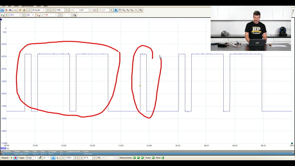
| 39:43 | So this is the signal that I showed you to start with. |
| 39:47 | So we've got something that's got a square wave to start with and then it's got this little detail here. |
| 39:53 | So to get this, basically the oscilloscope is looking at the voltage on its probe, 1000s of times or in this case millions of times per second and plotting it as it changes with time. |
| 40:07 | So obviously if we do this at a very very high frequency it gives us a good amount of detail, we're really seeing exactly what's happening. |
| 40:14 | Now that's not such a big deal as we go across a square wave transition like this but it does become a big deal as we go through something that's changing quite quickly like this detail here. |
| 40:27 | So to highlight this and sort of give you an indication of what can happen if the sample rate is set too low, let's just have a consideration I'm going to probably, or try my very best to do this and make sense of it but we just sort of plot out what our sample rate is. |
| 40:42 | Let's go here and we'll see if I can make this make sense. |
| 40:48 | Hopefully it will. |
| 40:50 | Alright so if we're looking at samples like this, and I'm going to draw it down below here, but basically we're going to go, start at this sample here, we're going to go over here because obviously our voltage isn't changing. |
| 41:01 | Then we get to this sample here, between this sample and this sample the voltage has dropped significantly but we don't capture a sample where it's actually changing so what we'd do between this sample and this sample, we'd sort of end up with an angled line coming down, then obviously out to this point here, again our voltage isn't changing so we're straight lined there. |
| 41:21 | From here to here, kind of miss this detail so at this point here we're back up, so we sort of end up going like this. |
| 41:29 | So hopefully you can sort of see if you've got a low sample rate, the detail that we want to see can easily be missed. |
| 41:38 | In this case, we've completely overlooked this big spike that's occurred here, doesn't look like that's happened at all. |
| 41:44 | So we do want to set a sensible sample rate. |
| 41:48 | Generally the sample rate, the default sample rate here I think on the PicoScope comes in at 1 mega samples per second, 1 million samples per second and that should be ample for just about anything we're doing in the automotive industry. |
| 42:05 | Probably overkill if anything, we don't really deal with anything too spectacular that's going to need that particular sample rate but there's no real downside of oversampling so to speak, essentially looking back at our diagram, what we have in that instance is where we're basically sampling at exactly the same point because the voltage isn't changing so that's what the knock on effect of that is going to be. |
| 42:30 | Alright the other thing I'll just talk about quickly which is probably the most frequent cause of trouble when we're using an oscilloscope and we haven't really, or don't understand how the scope works is we hook up and we're basically looking at a blank screen with no signals. |
| 42:48 | So this can be really frustrating and what's going on? So obviously we want to start with the basics, have we got our probes hooked up correctly? Have we got good electrical contact to the conductors that we're trying to break into? From there what we also want to do is make sure that we've got sensible settings for everything so if we come back to setting play here and our sample is running. |
| 43:13 | We should on the PicoScope be able to start at least by setting our voltage per division here to auto and again that's just going to span our channels so that the signals we're looking at are at least visible. |
| 43:31 | The other thing that I will mention there, we already looked at it but if we've set something that is too low, we're not going to really see anything but we do have this little warning that pops up, remembering just telling us that our channel is over voltage. |
| 43:46 | So if we see something like that, that is a good indication that that's our problem and again just going to the auto should fix that. |
| 43:52 | The other aspect there is making sure our time per division is set sensibly and again we can basically come up with something, we can move these around and generally starting with a higher time per division is a good place to get started. |
| 44:10 | That'll let us see an overview of the waveform before we sort of jump in and start digging in a bit deeper so hopefully, just a very brief overview of the scope, it's again a tool that you're not going to need very often but when you do need an oscilloscope unfortunately there's also just about nothing that can come close to its ability so very very powerful and again for not a lot of money these days so if you are serious about tuning and building wiring harnesses, something that you should seriously consider. |
| 44:43 | Alright we'll jump into our questions now and see what we've got. |
| 44:47 | And looks like we've got no questions so either I've done a great job of explaining that and there's no questions because of that or everyone has fallen asleep. |
| 44:56 | Either way, if you do have questions at a later point if you're watching this in our webinar archive, please feel free to ask those questions on the forum and I'll be happy to check them out and answer them in there. |
| 45:09 | Thanks for joining us and hopefully we can see you again next time. |
Timestamps
0:00 - Introduction
0:26 - Traditional oscilloscopes
1:13 - Modern oscilloscopes
1:58 - Applications
3:17 - Why can't we use a multimeter?
5:18 - What can be tested with an oscilloscope?
7:10 - Built into some ECUs
7:40 - Link ECU test setup
11:39 - Parts of an oscilloscope display
16:15 - Getting a signal into the scope
22:54 - Changing milliseconds per division
25:39 - Changing voltage per division
27:01 - Changing vertical location
28:03 - How to stop scrolling
31:59 - Setting reluctor sensor arming threshold
35:21 - Measuring incoming signals
38:51 - Sample rate
42:30 - Troubleshooting no signal


