311 | Introduction to ECU Master PMU
Summary
Power Management Units are becoming increasingly common and in this webinar we’ll take a look at the ECU Master PMU16 and understand how it works, how to communicate with it and how to utilise it to power and control various functions on our car.
| 00:00 | - Hey team, Andre from High Performance Academy, welcome along to another one of our webinars and today we're going to be getting a bit of an insight into the Ecumaster PMU16. |
| 00:12 | Let's just get my laptop out of the way and we'll get this little guy under our overhead. |
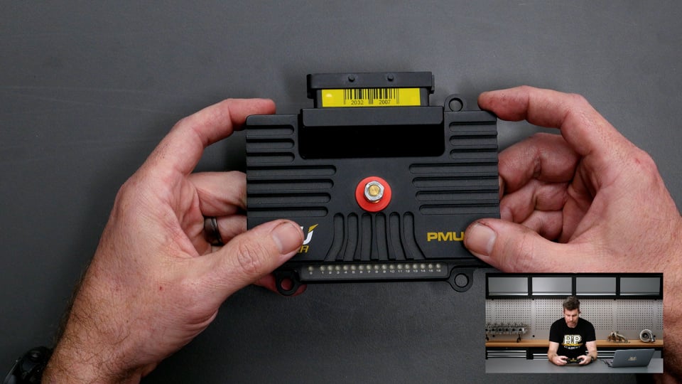
| 00:17 | So this is probably one of the smaller form factors I've seen of a power management unit. |
| 00:23 | it is really tiny for the technology it's packing in and really easy to fit into just about any installation. |
| 00:33 | Now we'll talk a little bit more about what these are if you are fresh to power management units but of course we do have our 12 volt stud here which is our battery supply. |
| 00:43 | We've got our connector for our wiring and this also actually includes a range of LEDs to give a bit of a status indication of what the PMU is doing. |
| 00:53 | I think off the top of my head those PMU16s are relatively affordable as well, last time I checked I think they were a bit under $1000 USD. |
| 01:02 | Don't quote me on that but in terms of the range of PDUs, PMUs, PDMs out there on the market, it is in my opinion probably one of the more affordable and also really feature packed. |
| 01:16 | So let's just roll back a little bit and for those who haven't heard of a power management unit before, we'll just talk briefly about what they are. |
| 01:24 | Essentially it is a solid state electronics, it's a way of replacing our conventional fuses and relays. |
| 01:31 | We're controlling the power distribution to all of the circuits in the car. |
| 01:35 | Now it's not just that, there are some really big advantages in using a power management unit over fuses and relays. |
| 01:44 | First of all, the most obvious is that if we have an overcurrent situation we obviously need to protect the circuit, if we don't do this we're going to get excessive heat being generated and a worst case scenario, it can end up in a fire. |
| 01:59 | Obviously we don't want that so this is why we need to fuse our circuits. |
| 02:04 | The problem with conventional fuses is that they're a 1 time thing and essentially if the fuse blows, that circuit is going to need to have the fuse replaced in order to get it back up and running again. |
| 02:17 | This can be problematic, particularly in a motorsport application where it could sideline the car resulting in a DNF. |
| 02:23 | There's some technology inside the power management units that allows a little bit of smarter fusing. |
| 02:29 | The fusing is electronic, we can retry a circuit a given number of times and we can rest it between tries to allow things to cool back down. |
| 02:38 | Now it's not going to fix something that's dramatically broken, it's not going to fix a short circuit for example but what it can do is potentially be enough to allow us to limp the car back to the pits. |
| 02:50 | Now on top of this as well, we've got a lot more flexibility in the control strategies that we use in order to function a particular output. |
| 02:59 | We're going to be looking at some of those as we go through today's lesson. |
| 03:04 | Now on top of this, one of the other big advantages is the integration of our inputs or the way we can switch our inputs. |
| 03:11 | So let's say conventionally we're talking about how we would function a thermofan. |
| 03:16 | Now what we could do is have a switch on the dashboard, a physical switch that we'd need to turn on or off. |
| 03:23 | Most often we're probably going to end up having the ECU control, a relay to switch that fan on and off using an auxiliary output. |
| 03:32 | So how that works is we wire the auxiliary output from the ECU which will switch to low side, switch to ground in other words and we wire this to the control circuit on our relay and then the relay, when it's triggered will supply power through to our fan. |
| 03:49 | That allows us to then use the ECU to control when the fan will switch on and off. |
| 03:54 | So obviously we don't want the fan running all of the time. |
| 03:57 | We might switch it on at maybe 92° and switch it off again when the temperature drops to 88. |
| 04:02 | So that gives us that flexibility, we still need to wire it. |
| 04:06 | I'll also come back a moment and just talk quickly about relays. |
| 04:10 | And I apologise for those who are up to speed with all of this but it's important just to get a bit of a grounding here. |
| 04:15 | Now relays essentially are just a mechanical switch that allows a low current output from out ECU to switch a much higher current. |
| 04:24 | What I mean by this is the thermofan that I was just talking about, that might pull let's say 12 to 14 amps, maybe much more with the in rush current. |
| 04:34 | The circuitry inside our ECU would not be able to cope with that. |
| 04:38 | Maybe the auxiliary output can handle 500mA or something of that nature so that allows us to use a low current output from the ECU to switch that much higher current. |
| 04:49 | OK the other aspect here is this is really often overlooked, when people are weighing up the expense of a power distribution module. |
| 04:57 | Obviously there is a cost involved, make no mistake, there's definitely a cost involved. |
| 05:03 | But particularly if you are paying someone to wire up your car, it is really important to factor in the saving in labour in parts compared to installing fuses and relays. |
| 05:16 | Fuses relays and switches are some of the more time consuming aspects of a wiring harness. |
| 05:21 | So there's usually several hours that would go into this plus the parts that you'll be saving by using a power management unti. |
| 05:28 | You factor in all of the other advantages, the slight addition that you're going to have to pay can seem worthwhile. |
| 05:35 | The other aspect here is it does make it much easier to integrate CAN keypads so I don't have the keypad in front of me, it is installed in our car but if we switch across to my laptop screen, the Ecumaster product works with the Blink Marine CAN keypads. |
| 05:51 | So the sample of what you see is over here. |
| 05:55 | They're available in a number of different configurations, number of buttons, you can switch out the icons on these buttons, you can control the colours, lot of flexibility there. |
| 06:05 | The advantage with this is even with the higher key count keypads, you're only running 4 wires to that keypad. |
| 06:15 | You've got 12 volts and earth and then CAN high and low, all of the messaging is via CAN so incredibly quick and easy to wire up one of these keypads and then as you'll see, very easy to configure from within the power management unit. |
| 06:29 | Now on top of that, you can still have hardwired switches into a power distribution module if you like. |
| 06:36 | There's always going to be analog or digital inputs that you can wire up to a switch. |
| 06:40 | So the flexibility with how you're going to function these outputs is pretty wide. |
| 06:47 | So what we want to do, we'll jump into our Ecumaster PMU configuration software in a moment, we're just going to take a bit of a tour of it and then start looking at some functions. |
| 06:58 | I will remind you at the end of the lesson we will have a Q&A session so if there's anything that I talk about you'd like me to go into a little bit more detail, then please feel free to ask those questions at the end. |
| 07:09 | Right so this is what we're going to be faced with on my laptop screen when we open up our PMU. |
| 07:16 | Now I have gone ahead and loaded up a configuration just so we're not starting from scratch. |
| 07:22 | Don't worry about what we've got in there, I will cover off what is going on as we go through this but before we focus on this page here, because there's a lot more going on, this is our main page where we're going to be doing our usual tuning or calibration workflow. |
| 07:39 | Let's just start by moving across to our configuration tab and I'll just cover off some of the basic configuration here. |
| 07:47 | Now you're not going to need to spend a lot of time on this but sometimes when you're doing your base configuration you will need to start here so for example we can see that we can set up password protection. |
| 07:58 | Not something I'd usually do, I'm not a big fan of protecting my calibrations on ECUs or power distribution modules but if you want to stop someone tampering or seeing what you're doing then absolutely you have the ability to do that. |
| 08:12 | The PMU also has onboard logging which is pretty handy for seeing what's going on so you can set that up here. |
| 08:20 | Now while it can log, I don't typically use it as a logging hub. |
| 08:25 | I like to do all of my logging in my dash so what I can do is basically log this information in the dash with everything else that's coming from the ECU in other sensors so it just keeps everything in one place but absolutely you can log in a PMU. |
| 08:40 | We can also set up here some global outputs, nothing particularly fancy here. |
| 08:46 | We've got a global filtering on our inputs as well as we can set up a master retry channel so basically you can set up an input that will retry all of the outputs. |
| 08:57 | We next have our CAN bus setup so we've got 2 CAN buses on the PMU, this is the setup for CAN bus 2, nice feature with this is it has a software selectable termination resistor. |
| 09:10 | For those who aren't aware of what that is, a CAN bus does need to be set up and built in a specific manner. |
| 09:18 | Particularly if it is over 2 metres long we will need a termination resistor which is 120 ohm resistor at each end of the bus. |
| 09:26 | Under 2 metres, you'll need that at one end of the bus. |
| 09:28 | So you can basically choose how your CAN bus is going to be wired based on where the PMU is in your CAN bus and if it is at one of the ends you can use that terminating resistor. |
| 09:40 | And then we also have the ability to set the CAN bus speed. |
| 09:45 | Then we have our standard CAN stream as well, so this is the information that I'll be sending to the dash. |
| 09:52 | So that is our send standard messages to CAN, so that is the status, voltages, current etc for all of the channels. |
| 10:00 | We can select which CAN bus that would be on the base address etc. |
| 10:03 | And then interestingly as well, the PMU has an inertia switch as well. |
| 10:09 | So what this does, if you've got it enabled, I haven't but you can set a G force, it's got an internal G sensor. |
| 10:17 | Basically the idea is that if you are involved in a crash, the G spikes above your set point, it will disable all of the outputs for safety. |
| 10:26 | So a nice feature, albeit it one that I am not using in this example here. |
| 10:30 | So that's out base setup there. |
| 10:33 | Nothing too tricky, let's move back over to our setup and before we get too involved, I'll just quickly give you a tour so you sort of know what's going on here. |
| 10:41 | So on the top left corner, we have what Ecumaster refer to as our project tree. |
| 10:47 | So this is where we're going to be spending most of our time, this shows us all of our inputs, our outputs, our functions, our tables as well as our CAN messages in and out. |
| 10:59 | There is a bit going on here because as I said this is an existing calibration but we will be talking through some of this as we go so fair bit to take in. |
| 11:11 | Down below this is our output monitor in the bottom left corner. |
| 11:15 | So this allows us, obviously when we are live with the PMU, it allows us to monitor the status and voltage current etc on every single channel. |
| 11:27 | So this allows us to get a real time sense of what's happening. |
| 11:31 | It will show us the current that is being pulled, what the peak current was which is quite important here so you can see we've got current and we've got peak. |
| 11:40 | So what's easy to overlook is that if we turn on a motor such as a thermofan or a fuel pump for example, what we will have is 2 situations, we're going to have the steady state running current. |
| 11:55 | So the thermofan for example might draw 12 amps when it's up to speed and running. |
| 12:00 | But when that fan is stationary and we initially turn it on and it's stalled, there's a massive spike in that current, it's called in rush current. |
| 12:09 | So we might go from 12 to 25 amps or maybe more. |
| 12:13 | A good example of this is the air compressor that is on our Toyota 86 for our paddle shift system, that will pull 19 to 20 amps steady state, we've seen 90 amps in rush current. |
| 12:26 | Now that's not necessarily a big issue because it's for such a brief period of time that we're not in danger of overheating our wiring. |
| 12:35 | That's fine but the PMU does give us the ability to monitor that so we know what's going on, as well as account for that which we'll see shortly. |
| 12:44 | Next we've got our analog monitor which is in here, I will just pull this out and make it a little bit bigger so we can get a better sense of what's going on. |
| 12:55 | So what we can see here is for example, we've got analog voltage 1 is our fuel pressure so we can physically wire sensors directly into the PMU which makes it a lot more useful than just relying on input from an ECU and then we can monitor, again when we're live, the voltage and then from the lookup table what that actually relates to in terms of our fuel pressure. |
| 13:20 | Obviously we've got that for all of our inputs, 1 other would be down here, analog voltage 9, this is our windscreen wiper park switch. |
| 13:29 | I won't be diving into the windscreen wipers today, those are an unusual and very specific case but the way we wire the high speed and low speed winding is critical, you will find that most PMUs will have dedicated outputs for these so you don't damage the PMU and then there will also be a park switch or home switch, that's what we're talking about here which tells the PMU when the wipers are in the park position so that it can actually make sure that it's reliably returning them to the correct spot. |
| 14:01 | Next we have our variables inspector which is in the middle here so basically any of the variables we create or bring in we can monitor in real time there, situation. |
| 14:13 | So for example there we've just talked about our park switch, we can see based on the configuration, the voltage thresholds that we've set, whether that park switch it true or false, basically it'll be 0 or 1. |
| 14:27 | For some of the other parameters here, which we will talk about in a little bit more detail, we've got fuel pressure which we've just discussed, manifold pressure and our RPM which are coming from the ECU. |
| 14:38 | We'll be able to see in real time what those values are. |
| 14:41 | Good for a sanity check there just to make sure that these values are configured correctly and are reading appropriately. |
| 14:50 | Next we have our graph which is on the right hand side and again obviously I can't show you this live because we aren't live with the PMU but allows us to monitor any of our outputs or in fact any of our channels in real time while everything is running. |
| 15:07 | So really good for fault finding and diagnostics and we can save those log files as well. |
| 15:15 | Lastly down the bottom here, we have some diagnostics and information around the PMU, including bore temperature, battery voltages, interna voltages etc. |
| 15:25 | So under normal circumstances, shouldn't be too much of a concern to us. |
| 15:30 | Alright so that's a really quick and dirty guide into what we're actually looking at on the setup page of our PMU. |
| 15:38 | What we want to do is just go through some of the more basic and common configurations that we're likely to be trying to use a PMU for. |
| 15:49 | And I think probably a good place to start here is with setting up a fuel pump. |
| 15:55 | Now there's a few different ways that we can function a fuel pump and I'm going to go through 4 of them. |
| 16:03 | So the first would be where we have an ECU controlling the engine. |
| 16:07 | And the ECU will typically have a fuel pump request. |
| 16:13 | Now why that's important is that basically if we end up involved in an accident and the vehicle, the engine stalls, maybe the fuel line is ruptured or something of that nature, if the fuel pump was to run continuously we do have the small but very real risk that the pump will continue pumping fuel out and cause a fire. |
| 16:34 | So the ECU control strategy will generally be that when we key the car on, it'll run the pump for a couple of seconds to prime it and build pressure, the it'll stop. |
| 16:44 | Once it sees an RPM signal, it knows the engine is cranking, it will again run the pump and it will continue running it until the RPM's dropped to zero for perhaps 2 or 3 seconds. |
| 16:53 | So what we can do is basically bring that request straight into the PMU via a CAN message so let's have a look at that. |
| 17:05 | So we have got this already set up so I am cheating a little bit but I will talk you through how this works. |
| 17:10 | So this is a CAN message input so what we need to do is start by creating a CAN object, CAN message object which is this guy here that I am on. |
| 17:22 | I'll double click on it so we can see what this is. |
| 17:25 | So first of all we can give it a name. |
| 17:27 | So this is a M150 message, it's coming from our MoTeC M150 to our PDM1, we've got 2 PDMs in this particular vehicle. |
| 17:36 | Next we need to define what CAN bus that message is coming in on, CAN 2 in this case and we need to define the base address so this just needs to accurately replicate the address that the ECU is sending this information out on. |
| 17:52 | Now on top of that, we can then select our type, in this case normal and our size, in this case 1 frame and what we will be able to see, which is a really nice feature on the PMU is it basically has its own built in CAN sniffer so we'll be able to actually see that we are in fact getting data on that particular address that we've defined. |
| 18:15 | OK so that's the first part, we've now said we're looking for data on this particular address, now what we want to do is actually create the channel that we're going to use. |
| 18:25 | So that is here, our CAN bus inputs, the last one was a CAN bus object. |
| 18:31 | So we've given it a name here, called it fuel pump control. |
| 18:36 | The message object that that is coming from is exactly what we've just looked at, our M150 PDM1 and basically through this we can then define where abouts that is coming from. |
| 18:47 | We can also in this case there is a single bit that's changing from 0 to 1 so we are extracting in this case a bit field, the bit count is 1, it's 1 bit long and the bit position is 0 so all pretty straightforward. |
| 19:03 | Again if we were live with this, what we'd be able to do then is look at what that live data was coming through as and down here where it says result, as that fuel pump request turns on and off, that should go between 0 and 1 so it allows us to do a bit of a sanity check and make sure, yep we've got the right information, it is changing as we'd expect. |
| 19:24 | So this is nice and easy because once we've done this, I say easy, I know if you're fresh to CAN it might seem like heavy lifting but honestly it is really easy and we do have our CAN bus decoded course if you want a deeper dive into CAN. |
| 19:40 | But the benefit of this is it requires no wiring between the ECU and the PMU, obviously over and above our CAN bus. |
| 19:49 | So no matter how many outputs you want to control from the ECU, we're doing this via CAN, we don't need to add any wiring so really comes back to what I was saying, it simplifies our wiring. |
| 20:01 | OK so at this point we should have our fuel pump control set up and we should be able to also in our variables inspector, got that same function there, fuel pump control, we'll be able to see that going from 0 to 1 if everything was working. |
| 20:16 | So once we know that that's working, now we can actually set up our fuel pump control so it's actually functioning the output. |
| 20:22 | So we'll scroll down here to our outputs and we've got 2 outputs here for fuel pump, we've got a lift pump and then we've got a high pressure pump. |
| 20:30 | Both of these are functioning off exactly the same way so let's have a look at our fuel pump main 1. |
| 20:37 | Double click on that. |
| 20:39 | And we've got all of the information here that we need. |
| 20:42 | So first of all we're going to give it a name, actually what I'll do, I'll just close that down for a second and if we were going to be setting this up and I wasn't just modifying one, we do have the output setup icon right there so get that out of the way, power output, we click on this and it would start up, give us a fresh page that looks exactly like this. |
| 21:06 | However I'm modifying what we've already got so we start with our name. |
| 21:10 | Then we define where abouts this output is coming from. |
| 21:13 | So in this case we were using a single channel, we can add in or double up on pins if we need to, if we want to get more current handling capability. |
| 21:24 | In this case output 12 can handle a maximum of 25 amps continuous and that's absolutely fine for our fuel pump. |
| 21:31 | So let's have a look at how we've got this set up, we've got our in rush current set up at 25 amps, probably a little bit light but not actually an issue. |
| 21:39 | We've got our maximum current set at 20 amps which is above and beyond where we're ever going to normally be operating this, probably pulls about 14 amps maximum. |
| 21:48 | Our in rush time as well so basically this will allow 25 amps for up to 1 second. |
| 21:52 | That in rush current is going to literally last maybe a couple of hundred milliseconds at the absolute most so that's not an issue. |
| 22:00 | Then we have our retry setup so again as I mentioned, this is the advantage of the PMU over and above a fuse. |
| 22:09 | If it blows, if the current peaks above 20 amps it's going to cut off that circuit. |
| 22:13 | What it's then going to do is wait for our retry time out, in this case 1 second and then it's going to retry that output, it's going to do that up to 10 times. |
| 22:23 | After 10 times it's going to go nah, this is not right and it's going to cut that for good. |
| 22:28 | Alternatively on mission critical outputs you can click it to retry forever. |
| 22:33 | Obviously it's still going to cut off the channel if the current goes excessive but obviously it's going to also build up more current if you did have a hard short to ground or something of that nature. |
| 22:45 | Alright so that's the actual setup here, now we need to tell the PMU how to control that fuel pump. |
| 22:53 | So we've got a couple of options here. |
| 22:56 | We can have it default to on or off. |
| 22:59 | Obviously not what we'd want for a fuel pump, we can control it via a channel, we'll look at that shortly. |
| 23:05 | Or we can set up a formula. |
| 23:09 | So in this case our formula is pretty basic. |
| 23:11 | We have this setup here so that any time our fuel pump control is true, it's going to run it so let's just double click on this so we can see this. |
| 23:23 | So the operation, we can choose what operation we're going to be using here, we'll look at our drop down menu, there are a variety. |
| 23:30 | So it's true, it's false, equal to, not equal to, less than, greater than etc, the list goes on. |
| 23:36 | So in our case, very easy though, we want our fuel pump to be running when our fuel pump control is true. |
| 23:42 | We can also set a true and false delay. |
| 23:45 | We'll look at how we can use that in a moment. |
| 23:48 | For this case, the fuel pump delay is defined by the ECU's control so we don't need to worry about that. |
| 23:55 | So basically at this point our job is done. |
| 23:58 | So that is our first way if we have a CAN input that will be controlling our fuel pump. |
| 24:06 | Close that down, so the other way we might want to do this is if we have a wired input from our ECU. |
| 24:13 | So this would be where the ECU is still providing an auxiliary output that is a fuel pump function. |
| 24:18 | So I'm not talking about a physical switch to turn the fuel pump on but where we've got the old school way, maybe we're adding a PMU to an existing setup where we have a wired output to a relay, instead we can just bring that into the PMU. |
| 24:32 | So let's have a look at how we would do that. |
| 24:34 | And I think I'm going to have to set this up from scratch. |
| 24:37 | So what we want to do is start by going to our top left here and the analog input and set that up. |
| 24:43 | Click on that. |
| 24:45 | So we need to give it a name. |
| 24:46 | So I don't want to call it the same thing so let's call it fuel_pumps, that'll be fine. |
| 24:54 | We need to define what analog input pin it's on. |
| 24:58 | So let's say that's wired to analog 8, no problem. |
| 25:02 | And now we set this up as to the type of switching. |
| 25:05 | In this case we're going to be switching to ground so it's going to be active low. |
| 25:09 | It does need a pull up resistor as well, otherwise the voltage will flow. |
| 25:14 | Basically the pull up resistor to 5V will essentially make that go high when the ECU isn't pulling it to ground. |
| 25:22 | So basically if our voltage is greater than 3.5 volts, the result of this is going to be 0 or false. |
| 25:31 | If we are below 1.5 volts, there's a bit of hysteresis in there, we're going to be true. |
| 25:36 | So that sets up our fuel pump's analog input so it's as simple as that. |
| 25:41 | Once we've done that, what we can do now is go back down to our fuel pump and let's just modify that control. |
| 25:49 | So now instead of our formula being fuel pump control, we'll just double click on that and what we'll do, actually we'll start from scratch, we'll just delete that altogether and this will be what it looks like if you come into this fresh. |
| 26:03 | Obviously we don't need to modify anything up here, that's all exactly the same. |
| 26:06 | Let's click add here and again we're going to have the operation, it's going to be is it true, and our channel in this case was fuel_pumps, should autofill, it does, analog fuel pumps. |
| 26:22 | And here we again have the ability to have a true and false delay but again we don't specifically need those because we're going to be using the ECU control so that'll allow that delay, so I just cancelled that but you basically get the idea. |
| 26:38 | That would set that up to run off a wired input straight from our ECU. |
| 26:44 | Third option, let's have a look at how we could do this, forgetting about the ECU altogether and instead we'll just use the PMU for our control. |
| 26:54 | So we need to think about what we're going to want in order to do this. |
| 26:59 | And we're going to need an RPM input so that the PMU knows when the engine is cranking. |
| 27:05 | We're also going to probably want an ignition input as well. |
| 27:09 | So let's have a look at our RPM for a start and I have already got this coming in so we'll just come back up to our message object. |
| 27:19 | So in this case our message object here is coming from our MoTeC M150 ECU, MoTeC M150 to C125 communications just to be really clear. |
| 27:30 | And we've got the address that that data is being transferred on which is hexadecimal 640. |
| 27:37 | So that sets that up, we've now got a message object on that CAN address. |
| 27:41 | OK now we can extract each of the pieces of information we are interested in that are coming across on that CAN address. |
| 27:48 | We can see we've got two here, we've got manifold absolute pressure and we've got RPM. |
| 27:53 | For the purposes of our discussion here, I'm interested in our RPM so let's see how we've set that up. |
| 27:59 | So this is coming from that message object that we just looked at. |
| 28:02 | It is in this case a 16 bit number, we've got our byte offset is 0, so it's nice and easy, it's coming through on our first byte and in this case we can also set up our multiplier, divider and offset if required. |
| 28:18 | Now that's going to depend on the data we've got coming through but in this case we don't need any of those and what we again would see in live data is those values changing and if we've got the right piece of data being extracted and our multiplier, adder and divider are correct, we would see our result here would just replicate our engine RPM. |
| 28:41 | Now why this is important as well being able to view this data live is quite often with some of the data, there will be a multiplier involved so there can be a bit of fiddling back and forth to get the RPM to read correct instead of an actual RPM of 1000, we might end up seeing that that actually represents in the PMU as 100 RPM. |
| 29:03 | Easy enough to fix, just set our multiplier to 10X and that will correct that but just allows us to sanity check that and make sure that that is correct. |
| 29:13 | OK so we've already got our RPM set up, I just wanted to go through that. |
| 29:17 | Let's see how we could set that now. |
| 29:20 | So we'll come back down to our fuel pump and I don't know if I've got this but let's just see. |
| 29:27 | So first of all, I think we should have an ignition input. |
| 29:31 | Maybe not on this, we don't. |
| 29:35 | Let's just say that in this case our Motorsport Electronics kill switch is our input for our ignition switch. |
| 29:44 | So this is our ignition switch, even though it's not quite what it is. |
| 29:46 | So this is going to basically run our fuel pump when the ignition switch is on and it's going to then run it for 3 seconds. |
| 29:56 | So that's going to be the first part of our setup here. |
| 30:01 | So replicating the way, when that ignition switch goes on, we're going to run it for 3 seconds and then switch it off. |
| 30:08 | Now that's obviously not the only part of this equation though. |
| 30:10 | We also want to add here that when our RPM is in this case, our operator is not going to be "is true", we're going to go with greater than. |
| 30:25 | Is greater than let's say 50 RPM. |
| 30:28 | We don't need it to be very high, basically as soon as it starts cranking, we want the fuel pump to run. |
| 30:34 | We want the fuel pump to start, we want it to start with no delay. |
| 30:37 | So we'll leave our true delay to 0 but this is where we can set the off delay. |
| 30:42 | So in this case, the false delay, so when this goes from true to false, we're going to delay that by 3 seconds so that's going to replicate that. |
| 30:51 | However, I have just messed that up, we do need to be a little bit mindful of the way the order of the tree, so we'll just go back to how this was. |
| 31:01 | So how I set that up initially, the value needs to be basically both of these need to be true, the RPM has to be over 50 and our ignition switch needs to be on. |
| 31:12 | We want these set up as separate things so what I'll do is just move these down. |
| 31:17 | So now you can see that it's an or not an and. |
| 31:21 | So we've got our ignition switch on, or our RPM is greater than 50 RPM and then it'll delay false for 3 seconds so that would be how we could set that up and if we wanted the PMU to do the actual control, provided of course we've got that RPM signal going into the PMU. |
| 31:42 | So I'll cancel that out. |
| 31:45 | As I cancelled that out, I just actually also thought, the way I've just set that up, wouldn't quite work how I intended, the ignition switch would need to be a pulse where it would turn on for 3 seconds and then turn back off so how I had that actually set up, it would run until the ignition switch was turned off and then it would turn off for 3 seconds. |
| 32:09 | Just making sure that we understand that, I just made a little error there with that setup. |
| 32:13 | OK now let's also look at a 4th and final option for our fuel pump. |
| 32:18 | Let's say we want our ECU to control everything just like we've already looked at but let's say we're running different fuels in the car and we want the ability to pump the fuel out so we can change fuel. |
| 32:30 | We might want to do this using a switch or a button on our CAN keypad so let's have a look at how we can do that. |
| 32:37 | So what we'll do is we'll come up here to our CAN key button, or CAN pad, just get my words out here. |
| 32:45 | And we'll double click on this. |
| 32:47 | So looking at this, we can give it a name. we've called it keypad, nothing particularly outrageous there. |
| 32:54 | We can set up what type of keypad we have configured. |
| 32:58 | In this case it's a 4 x 2 so an 8 key keypad. |
| 33:02 | Obviously we can choose this from a drop down menu. |
| 33:06 | We also have what CAN bus that is on and the CAN ID. |
| 33:11 | That's the basic setup, now we can, once we've got that all configured we can then function those buttons. |
| 33:18 | So let's say we want to use this button 6 here which is currently unused so we'll double click on that. |
| 33:26 | And we can give it a name, so let's call this fuel out. |
| 33:32 | We can select the type of button so in this case we've got a latching switch. |
| 33:38 | We can have it non latching which would mean that it's only going to pump when we've got the button held down. |
| 33:44 | So in this case, latching switch is what we want. |
| 33:47 | The first state will be 0 or false, last state will be true which is obviously what we want and it will default to off. |
| 33:54 | We also have the ability to control the colours in both positions as well so gives a visual indication of the button function. |
| 34:03 | Alright so let's set that up. |
| 34:05 | It now changes to fuel out so that's now set that as a channel that we can utilise. |
| 34:11 | Let's click on OK. |
| 34:14 | We've got a CAN bus speed error but let's not worry about that. |
| 34:18 | Alright let's come back down to our fuel pump output, probably should have saved that and I didn't. |
| 34:24 | That's OK though, we've got our fuel pump control as one of our functions. |
| 34:27 | So what we want to do now, we're going to add another "or". |
| 34:30 | In this case we also want to run this when our fuel out is true. |
| 34:39 | So fuel out is true, we again don't need any delays so now what this would do, we've obviously reverted to one of our earlier examples where we've got the CAN message for fuel pump control. |
| 34:49 | So the fuel pump will run when that CAN message is true or when our keypad, we've got the key for our fuel pump that is in the true position as well. |
| 35:01 | So really easy to basically set this up to suit your own requirements. |
| 35:06 | Now let's have another look at another simple function which would be maybe providing power to our ECU. |
| 35:17 | We've actually got a different PMU that's providing power for the likes of our ECU itself, maybe our ignition coils etc so that's not in this at the moment but let's look at how we can do this. |
| 35:30 | So let's take our output here, we've got one that is spare, we've got output 14 which is currently called test so let's have a look at that one. |
| 35:44 | Double click on it. |
| 35:46 | So let's call this ECU power. |
| 35:53 | OK so I don't know what I was testing with this but chances are that our ECU is definitely not going to require anything like 25 amps so let's give it some more realistic values, might pull 15 amps, maybe our in rush current might be 20 and everything else should look pretty good there. |
| 36:14 | Now our control here, this is where we need to figure out how this is going to actually work, so at the moment it's set to defaulting to on. |
| 36:23 | What we really want here is a formula and what we could do here is again just let's assume that our Motorsport Electronics kill switch is our input. |
| 36:35 | So we've already got that coming into the PMU so if we type in MSEL, that's what we've called it here for those who aren't aware, Motorsport Electronics, MSEL, they make a killswitch, a solid state killswitch that we use on a number of our vehicles. |
| 36:49 | So we can select that. |
| 36:51 | So we want that to be true and then we can select OK. |
| 36:56 | Now maybe we want another function here so that it's not just when our killswitch is true. |
| 37:01 | So let's see how we could do that. |
| 37:04 | We'll come back up to our CAN keypad and we're running out of buttons now but we've got button 7 is currently free so let's double click on that. |
| 37:13 | What we're going to do is call this maybe ignition, probably we should have done this first and we could have used this for our fuel pump example. |
| 37:23 | Again it's a latching switch, 0 and 1, everything's looking good there, maybe we want our colour there to be red when it's on. |
| 37:31 | All good, we've got that done. |
| 37:34 | Click OK, that'll again ask us about our CAN bus speed but we're not worried about that. |
| 37:39 | Alright coming back down to our ECU power, where'd I put that, that one there. |
| 37:45 | So we want this to be active when the killswitch is true, so the killswitch is on and we also want our ignition to be true. |
| 37:55 | So we'll find that by just typing in ignition. |
| 37:58 | And that is done. |
| 38:01 | So this is, both need to be true, we want the, let's move that down, the killswitch to be true and our ignition both to be true, that will then provide power based on our current capabilities up here out to our ECU. |
| 38:18 | So this would be something really common that we're doing when we're setting up the power supplies for things like our ECU, our ignition coils, maybe you've got a separate channel for injector power, whatever it is that you've got set up, that is how we can do that. |
| 38:33 | Next let's have a look at a headlight function. |
| 38:39 | So I'm going to have to repurpose some of these. |
| 38:42 | So let's start by looking at this as a slightly more advanced function where we may want to monitor our voltage perhaps and basically disable non critical functions if we've got maybe an alternator that has failed. |
| 39:01 | So this is again some of the more advanced stuff that we can do with our PMUs to help potentially limp a car back to the pits just if it needs to be conserving our battery voltage. |
| 39:13 | So what we'll do here is we'll start by just adjusting our keypad setup so we've got a button for our headlights. |
| 39:20 | So we'll come across to that again, let's just repurpose here our fuel out, we'll call this headlights. |
| 39:29 | OK nice and easy and we'll click OK. |
| 39:34 | Still asking me about that CAN bus, it hasn't changed, don't be surprised. |
| 39:37 | Alright we'll now repurpose our output that we just set up for our ECU power and we're going to call this obviously headlights. |
| 39:46 | OK probably we're there or thereabouts with our current but that's not really a concern right now. |
| 39:54 | OK so let's just delete our functions at the moment and we might add here, maybe we want that our headlights will run when our killswitch is true so we'll find that again, MSEL, that's fine, so basically nothing's going to operate when our killswitch is not on. |
| 40:13 | And obviously we also want to add in here that our headlights button has been pressed. |
| 40:20 | So let's just type in here headlights and we've also got a headlight flash button as well for racing but that's not important. |
| 40:28 | OK so that's going to basically give us a situation where the headlights will turn on off a button, this is pretty much what we'd expect. |
| 40:38 | Now let's get a little bit more advanced with this. |
| 40:41 | So there's a few ways that we can do this. |
| 40:42 | What we might want to do is monitor our voltage and our RPM so let's say we'll add a function here and we can monitor, I'm actually going to have to set up a function here to monitor our voltage I think, no we don't, we can monitor PMU battery voltage here. |
| 41:03 | OK so is greater than let's say in this case 12.5 volts or something like that. |
| 41:12 | So basically when our car is functioning, is running normally, what we should end up with is our battery voltage should be about 13.8 to 14.2 volts. |
| 41:23 | If the alternator stops charging, we're going to drop immediately to probably more like 12, 12.5 and as the battery discharges, we're going to see that voltage drop. |
| 41:32 | So in this case, 12.5 so this has to be above 12.5 volts and we could put in a delay here, maybe we want this to give a little bit of a time and maybe our voltage will drop momentarily below 12.5, we can bring in a delay if we want but that's going to basically get that done. |
| 41:52 | So in this case, for our headlights to function our killswitch has to be on, our headlight button has to be on and our PMU battery voltage has to be above 12.5 volts. |
| 42:04 | Now that's going to work, that's going to do what we want, probably the only thing I'll add in here is that if we've got the car powered up but the engine's not running, we probably get a situation where our batter voltage would be sitting at 12 volts so our headlights in this case wouldn't function sitting there stationary with the engine not running. |
| 42:24 | We can get around that if we wanted to as well, we could bring in maybe our engine RPM again as a function so all of that, again you can sort of see how you can build up these functions. |
| 42:33 | You can basically be as smart or as simple with these as you want, it really totally depends on just what you are trying to achieve. |
| 42:42 | Alright we are going to move into some questions and answers shortly so if you've got any, this is the time to start asking those, we've got one more function that I want to quickly go through. |
| 42:52 | Before we do that though, I'll just mention, the alternator safety override there that I just looked at for the headlights, obviously we could apply these to every non mission critical output that we've got on the car and obviously it's up to you to decide what in fact is non mission critical. |
| 43:12 | Headlights is probably a bit of a questionable one, if it's pitch black, I'd probably like the headlights in order to get myself back to the pits so there's some decisions that need to be made, I'm not here to tell you what you should and shouldn't be disabling. |
| 43:26 | Maybe windscreen wipers would be another one that's again a bit of a safety marginal consideration, heater/blower unit inside the car, maybe that'd be a pretty safe one to disable. |
| 43:37 | If you've got multiple fuel pumps, maybe you want to switch down to just one fuel pump whatever you feel you can get away with. |
| 43:44 | Alright the last one we're going to talk about is our water pump control. |
| 43:48 | So in this case if we jump into our output monitor here, we can see output one, we've got this set up for a water pump. |
| 43:56 | We'll double click on this in our project tree and see how this is set up initially as there are a few ways of doing this. |
| 44:04 | So we've got our name of course, water pump, it is on a single output which is a 25 amp output, we have a in rush current of 30 amps, a max current of 15 amps and again our in rush time is set to 1 amp. |
| 44:21 | Now it doesn't actually pull a lot of current, I think off the top of my head the Davies Craig pump that we're using is actually sitting at around about 9 or 10 amps under steady state conditions. |
| 44:33 | It's not a huge amount, it does create a problem which we'll talk about shortly. |
| 44:35 | Moving down here we've got our retry count. |
| 44:38 | Now because the water pump is not required to run continuously and we'll see that in effect shortly, I've got quite a long retry time here of 4 seconds, it's going to retry 10 times, obviously again up to you how you're going to do this. |
| 44:53 | And it is going to run off this channel EWP pulse control. |
| 45:00 | Now that's the key to this, this is a function which is another type of setup we can use in our PMU16 here, functions are set up from the little F icon here in the menu. |
| 45:16 | Now let's have a look at what this is, so I'll double click on it. |
| 45:20 | So of course with the function we give it a name, we've already seen that and this is how we are functioning this pump. |
| 45:27 | So there's 4 different operating modes. |
| 45:31 | So first of all, if our engine coolant temperature is between 10° and 50° what we're going to do is use a flash function. |
| 45:42 | So flash can be used for the likes of our indicators for example, basically something that we want to flash on and off. |
| 45:50 | In this case, what we're going to do is turn it on for 30 seconds and then turn it off. |
| 45:55 | Then once we are, sorry, should explain that a little bit more correctly. |
| 46:02 | It's going to turn it on for 10 seconds and off for 30 seconds, I'll just double click on that and we can see yeah we're using the operation flash, the time on 10 seconds, the time off 30 seconds. |
| 46:15 | So basically the idea here is the engine coolant temperature is low, it's under 50°C and what we want to do is move some water around as the engine's heating up but we don't want to flow it continuously because that will slow the engine's heat up, warm up. |
| 46:31 | OK so that's our first, when we're below 50°. |
| 46:34 | Our next one here is between 50° and 70°C and again we're using the flash control. |
| 46:42 | This time it's on for 10 and off for 10. |
| 46:45 | Now if you're wondering where these numbers have come from, I am essentially replicating the Davies Craig strategy within reason of how they control it. |
| 46:52 | OK so we're running it for the same amount of time but our off time has been reduced dramatically. |
| 47:00 | And then once we are over 70, between 70 and 80, these are a little bit out of order, we're going to be on for 5 seconds and off for 1 and then finally, should be down the bottom, once we're over 80° it's on continuously. |
| 47:16 | So that is how we can use pulse control or flash control I should say here to control how our water pump is running. |
| 47:24 | Works fine, that is how we have been using the pump in the car. |
| 47:29 | The other option which is how I initially set this up and it is a function that the PMU does offer, but we did find it was problematic in this instance, is to use pulse width modulated control which is where we can vary the duty cycle being sent out to the electric water pump and what this does is gives us the effect of basically speed control. |
| 47:50 | In essence we're varying the voltage that is being sent to the pump anywhere from 0 up to our full battery voltage. |
| 47:58 | Now the problem with pulse width modulated control in a PMU, irrespective of what power distribution module you are dealing with, whatever the manufacturer, it does create heat. |
| 48:07 | And this is a warning the PMU manual gives you and we tried this out and it just didn't work reliably so we reverted to what I've just shown you. |
| 48:17 | But we'll go through the process anyway, we could have probably got around this by doubling up the pins and giving us two 25 amp outputs to control that, probably would have got us around the problem but anyway, that's a story for another day so let's come up to our water pump control. |
| 48:37 | And what we've got here is a table, I'll just make sure I've got the right one. |
| 48:40 | So table, another type of configuration we can do in here, we can click the little table icon here that will bring that up. |
| 48:48 | And that will give us the table that we can set up. |
| 48:53 | In this case I've called this T_waterpump just so we've got a nice reference of what it is. |
| 49:00 | We don't need any decimal places, I've already configured this to be a 2D table. |
| 49:04 | We've got engine coolant temperature which we already know is coming in as a CAN message. |
| 49:09 | That's our X axis here and essentially the values here are the duty cycle that we'll be sending out. |
| 49:15 | So this probably needs some manipulation once you've got it up and running. |
| 49:19 | Obviously when the engine's running cold, we're running it at low duty cycle, 10% so it's going to give us a low pump speed and essentially sort of in the operating area we're up at 70% duty cycle. |
| 49:30 | Once we get hotter, we bring this up to 100%. |
| 49:33 | Now assuming we've got sufficient cooling capability in the system, what that should do is basically speed the pump up, cool the engine down and basically we should be sort of floating in the area around about here. |
| 49:45 | OK so that's our table, then we can use that to control our water pump, so let's come down here and we'll double click on that. |
| 49:55 | Now the option here that we need to enable is our PWM configuration. |
| 50:02 | And we can start by selecting a frequency that the pump's going to run at, it's going to depend on the actual device you're operating. |
| 50:10 | Then we can click on duty cycle so this is our duty cycle control and then we can choose where the duty cycle control is coming from. |
| 50:19 | In this case it's actually from a previous setup and what did I call this? Table. |
| 50:31 | Water pump there we go. |
| 50:32 | So that's going to give us the control, duty cycle control's going to come from that table that we just looked at. |
| 50:38 | And then we also need to figure what we're going to do to turn the pump on so basically this down here defines when the pump is going to function at all. |
| 50:47 | Obviously we wouldn't want to be using our electric water pump pulse control that we've just looked at so maybe here we would be running this pump any time the ignition, did we have that? Any time the ignition is active and then once the ignition's active, then it would be using the look up table on that pulse control in order to figure out, sorry the water pump control table in order to decide what to do with it. |
| 51:15 | Alright, a lot of information to take in. |
| 51:18 | Hopefully that's been a bit of a eye opener on what the PMU16 is all about. |
| 51:24 | Maybe it's given you some insight into how we can get quite creative with some of these control strategies and I mean really today we've just scratched the surface as well. |
| 51:34 | Of course if you do want to learn more about PMU installation and configuration, we do have our power distribution module installation and configuration course. |
| 51:45 | Goes into much more detail than I've been able to do inside a 1 hour webinar. |
| 51:50 | For now though I'll head over and have a look at our questions, if you've got more please keep those coming. |
| 52:09 | James has asked, are there any good resources on how you'd further incorporate a power management unit into a track use only vehicle to replace an OEM power distribution module? Yep our power distribution module installation and configuration course would be ideal. |
| 52:25 | That course, Zac presents and it does also give some really specific more advanced case studies on things like anti stall strategies so that if you're doing standing starts and you happen to stall the car, instead of having to actually restart the car manually, by just depressing the clutch the car will actually reengage the starter motor, obviously there's some requirements around that. |
| 52:53 | Also Zac gives another case study in terms of automatic backups, fuel pump setup as well. |
| 53:00 | So if you want to learn more about that, I wouldn't say, OEM power distribution module, I'm not sure specifically what vehicle you're talking about there. |
| 53:09 | I mean within reason we can replicate any OEM strategy as well, it just really depends on what you're trying to do and here, it's kind of really down to your imagination as well as what you're wanting to achieve. |
| 53:24 | Plohl's asked, if using, with an M1 ECU and a C125 dash, is there any reason you'd go a MoTeC PDM15 instead of the Ecumaster PMU16? I mean it's really a bit of a coin toss in my opinion. |
| 53:40 | I love the PDM product from, MoTeC, I've got two of their PDM32s going into my FJ40 project. |
| 53:48 | They're a well proven, very very reliable product. |
| 53:52 | We have to say obviously they're at a very different price point than the PMU product. |
| 53:56 | I would actually say all things being equal, the PMU does provide a little bit more advanced functionality than the PDM and I think that's probably more an indication that the MoTeC PDMs are a relatively old product compared to the PMU and haven't really seen too much in the way of updates. |
| 54:17 | I do believe that MoTeC have been working for a while on an updated PDM2 or version 2.0 if you like. |
| 54:25 | Not quite sure, any more information on that but I mean yeah it comes down to your own personal preferences, your budget plays a big part in this but it is absolutely possible to do all of the same things that the PDM MoTeC product will do on the Ecumaster product. |
| 54:44 | Will be a little bit more work in setting up the CAN communications both ways than if you were just using a MoTeC product is probably the only other thing that I would say. |
| 54:54 | Next question comes from Harley who's asked, could you set the keypad force on state as the fuel pump controls for the button shows on state when the ECU controls it but also allow you to activate manually, for example when the engine is off? Yeah I mean I can't see any reason why you couldn't do that Harley. |
| 55:14 | Plohl's asked, is there a quick summary of button functions, so if you have a few combinations for the keypad such as running the fuel pumps to empty the tank? I don't believe so, this is an area where particularly on the more complex installations where you've got a lot of functionality going on and maybe you've done some trick things, keeping some notes on the functionality can be beneficial. |
| 55:38 | I find this is a situation I get into with ECU installations as well where everything makes sense and is obviously front of mind while you're actually doing the initial configuration and setup but maybe you don't come back to that particular vehicle for 6 to 12 months and then you're sort of scratching your head trying to figure out now why was I doing that or this looks weird, why on earth is that set up like that? So that's where just keeping some notes can be beneficial to sort of fast track that when you come back to it. |
| 56:08 | Next question from Plohl who's asked, is it easy to set up functions for turbo timers or keep the car running for X time after an ignition is turned off? I haven't looked into a turbo timer function but absolutely it would just be a case of using a delay, kind of like we saw that false delay, that as far as I can see at a quick cursory glance would probably be the way I would do it. |
| 56:37 | You'd probably want to include some safety strategies around that. |
| 56:40 | Personally, this day and age, I don't actually care much for turbo timers, I wasn't a big fan of them when they were an add on module. |
| 56:48 | Really with water cooled turbos, provided you don't like to thrash your car red hot right up to your garage and then shut it off I really don't actually see the need for turbo timers these days. |
| 57:01 | Harley has asked, are these types of configuration options and functions typically available in most PDM/PMU devices from other manufacturers? That's a maybe is the answer there Harley. |
| 57:14 | For the more advanced products and I definitely haven't used every brand of PDM out there on the market but for the more advanced products I would say absolutely yes. |
| 57:24 | I have however used some more basic power distribution modules where you were very limited in the functionality you could provide. |
| 57:33 | So yeah it's really important to, before you commit to spending your dollars, I would probably look at the specfication sheet for the unit that you're looking at but more importantly, because it's always going to be free, download the software and actually get familiar with that and see the functionality that you are able to include. |
| 57:53 | Next question comes from Plohl who's asked could you use an external solid state relay to move the heat away from the PMU instead of pulse width modulated control even though you're adding a relay which isn't the point of the PMU? I mean yeah you probably could but your point is probably what I was going to raise. |
| 58:09 | I mean if you've got a PMU, adding a solid state relay external to the PMU kind of defeats the point. |
| 58:16 | So what we didn't try, and this is explained in the Ecumaster instruction manual, is you can add a fly back diode which will aid pulse width modulated control so that could have been enough. |
| 58:30 | Or alternatively if you've got a spare channel, doubling those up and giving a little bit more load capability on the output would have probably also sufficed. |
| 58:38 | And also that's going to depend to a big degree as well on the output you're trying to control. |
| 58:45 | One of the other areas we ran into a problem with is our air compressor. |
| 58:50 | That actually required two channels to be paired in order to control that while on face value the current draw should have been able to easily be handled by a single 25 amp output. |
| 59:03 | Just with that particular type of output, unfortunately it did require two so a little bit to understand there. |
| 59:10 | Alright that brings us to the end of our questions. |
| 59:12 | Thanks for watching and as usual if you are watching this in our archive at a later point, if you've got any questions on the topic, please feel free to ask them in the forum and I'll be happy to answer them there, thanks for joining us and we'll see you all next time. |
Timestamps
0:00 - Introduction
1:16 - What is a PMU?
1:35 - Advantages over fuses and relays
7:09 - Configuration
10:30 - Setup page
15:38 - Fuel pump setup example | ECU CAN request
24:06 - Fuel pump setup example | Wired input
26:44 - Fuel pump setup example | PMU controlled
32:14 - Fuel pump setup example | Fuel pump button
35:08 - ECU power example
38:35 - Headlight example
43:44 - Water pump example
52:09 - Questions


