313 | Selecting Autosport Connectors
Summary
Autosport connectors are the go to option when it comes to professional motorsport wiring harness construction, however many enthusiasts find it daunting understanding how to select a suitable connector. In this webinar we’ll learn how to specify a connector and how to understand the part numbers.
| 00:00 | - Hey team it's Andre from High Performance Academy here, welcome to another one of our webinars. |
| 00:04 | And today we're going to be diving into the world of Autosport or milspec connectors. |
| 00:10 | And for those who are maybe just getting started out on the journey of learning how to build proper professional motorsport grade wiring harnesses, learning about the ins and outs of autosport connectors can be pretty daunting and I'm using the term autosport here but TE are not the only manufacturer making these connectors. |
| 00:32 | We've also got the likes of Souriau, if I can get my words out straight, which is another manufacturer basically making completely interchangeable, compatible parts. |
| 00:42 | But understanding what these connectors are, the terminology that's involved as well as the tooling and the processes that we need to work with them is really important, otherwise you're essentially buying what can be quite an expensive connector kit and if you don't use it properly, if you aren't using the correct tooling and the correct best practices for assembling and pinning these out, you're actually going to end up with something that could be completely unreliable which is obviously the complete opposite of what we're trying to achieve so today's lesson is intending to give you a little but more insight and break down some of the barriers. |
| 01:21 | Making it a little bit less daunting and a little bit more intuitive to understand how these connectors work and what you need to know. |
| 01:29 | We'll give you some resources so you can spec these out to suit your own projects. |
| 01:34 | As usual, we will be having a question and answer session at the end of the lesson so if there's anything that I talk about that you'd like a little but more detail on, please feel free to ask those. |
| 01:45 | So first of all, what we do need to understand is that in the TE Connectivity Autosport range of circular connectors, there are actually a variety of different styles and if we just jump across briefly to the catalogue which we will be focusing on a little bit today. |
| 02:02 | As I scroll through this, I mean not really an Autosport connector as we conventionally know them but we've got the AS composite series. |
| 02:10 | Interestingly I think when we went to TE in the UK, these were actually developed exclusively at the time for the Williams F1 team, just something to note there, these actually genuinely are used on Formula 1 cars. |
| 02:25 | Scrolling up again we've got the Autosport Rally Micro, etc, etc, the list essentially goes on. |
| 02:33 | The style of connector is obviously going to play into a part of basically what size contacts we can use, which in turn defines what size conductor, what gauge of conductor that we're going to be able to use and basically also the number of contact locations or positions in the connector as well. |
| 02:54 | And these are really the key things that we're going to need to understand in order to be able to specify the correct connector. |
| 03:00 | Now while I've just talked about a variety of the different styles in the Autosport range, what we're going to be focusing on for today's webinar essentially is the standard Autosport range. |
| 03:11 | These are the bread and butter I guess of the Autosport connectors and these are the ones that unless you've got a fairly specific application, you're most likely to need, particularly if you're looking at something with a reasonably high pin count for the likes of a bulkhead connector or something similar. |
| 03:30 | Alright so one of the first things we need to do, even before we worry about the Autosport catalogue or anything to do with the Autosport connectors themselves is we need to really consider what wire gauge we're going to be working with on our particular project. |
| 03:47 | And there's a few elements to come into this, why we need to understand this is this is going to essentially drive our decision in a big way as to what connector shell size and contact arrangement is going to work for us. |
| 04:05 | So obviously that's one of the early things we need to understand. |
| 04:08 | When it comes to defining the correct wire gauge, there are a few elements that we need to consider here. |
| 04:16 | The first of these would be the application or current draw. |
| 04:21 | So for example if we were wiring up a fuel pump, it's quite possible that a fuel pump would be drawing maybe 10 or even 12, 15 amps depending on the size of the pump. |
| 04:33 | Very different for example to most of the sensors that we would have on our engine. |
| 04:39 | The senor current draw is likely be in the milliamp range so a very big disconnect there. |
| 04:46 | Even some of the actuators that we find on our engines, the likes of our injectors and our ignition coils, the current draw on those is likely to actually be very very low, particularly given that they are pulse width modulated essentially or they're pulsed on and off, they're not run continuous. |
| 05:05 | So current draw, the application of that. |
| 05:08 | Now the other thing we can get away with though, if we've got a situation where for example, 99% of our conductors are going to be very low current draw but we might have a situation where we've got 1 or 2 aspects that are much higher. |
| 05:24 | What we can do is actually double or triple up on the wires or conductors through the connector. |
| 05:31 | So a good example of this, we've got this off to the side, I might bring this in a little bit later, this is a harness that I have just about finished off for our professional motorsport wiring harness course as a worked example. |
| 05:44 | This is for our in house Toyota FJ40 project. |
| 05:47 | So this is the engine harness itself and the bit that I want to show you here or just talk about here is this particular connector, probably a little bit hard to see, I won't get it under our overhead but that particular connector there goes to the valley of the engine and in that particular connector, we've got a couple of elements, we've got the knock sensors for both banks, those are mounted inside the valley under the inlet manifold. |
| 06:12 | We've also got the starter motor solenoid. |
| 06:16 | So the exciter wire for the starter motor solenoid, not the main power feed, I'll just be really clear on this, but that starter motor solenoid runs through the bulkhead to the PDM and in this instance, I mean everyone's a little bit different but it's not uncommon for a starter motor to pull somewhere in the region of 10 to 12 amps on that solenoid when it's pulled in. |
| 06:40 | So with this whole harness, the wire gauge that I have chosen is 22 gauge which is a great choice in most instances for our actual sensors and actuators but a 22 gauge wire will probably support somewhere around about 6 amps total current. |
| 06:56 | So obviously there's a disconnect there, 6 amps, it's not going to support the 12 or so amps that I'm expecting that starter motor solenoid to draw so how do we do this? We simply run 3 wires. |
| 07:08 | So we've got 3 wires coming from our PDM, those go into our bulkhead connector here. |
| 07:14 | We've got 3 positions through that bulkhead connector that then run up to that autosport connector to our starter motor. |
| 07:20 | So these are the sort of considerations, don't think that you have to be in a situation where you have to run all the same gauge wire, don't think that you need a bigger wire gauge through the actual autosport connector to support that, you can branch out or splice together multiple wires in order to get the current handling capabilities that you want. |
| 07:45 | Now once you've got an idea of what wire gauge you're going to be using, this is, the next step is then going to be to work out how many positions you're going to require. |
| 07:57 | So that wire gauge comes into that point I've just mentioned there, obviously if we're in a situation where we need to double or triple up for a couple of our outputs, then that comes into our position count that we need to factor in so that's why this is one of the first things we need to do. |
| 08:14 | Have a really good think about what we're actually wiring up, what the current draw's going to be, any special applications like the starter motor in our instance there that we need to account for and then we can sort of sum up how many positions we're going to need to deal with. |
| 08:29 | Now while I'm still talking about wire gauge, I just want to talk a little bit more about what is common because this is a question we quite often get asked. |
| 08:37 | A lot of this, there's no black or white, it does depend to a degree on what you're doing obviously but also your personal preference and the application. |
| 08:47 | So as I mentioned, current draw on most of the engine sensors is incredibly low so the wire gauge is almost not a consideration, we could go to a very light gauge wire and still support the current draw quite safely for the likes of a manifold pressure sensor, fuel pressure sensor or throttle position sensor. |
| 09:06 | And we might go to 24 gauge or even smaller. |
| 09:10 | However there are a couple of other considerations. |
| 09:14 | Obviously smaller gauge wire is going to result in a lighter harness which is a great thing however maybe that's not the main driver for what you're doing. |
| 09:25 | For most of us in semi professional or club level motorsport, saving maybe 100g in a wiring harness is going to be absolutely pointless, it's not really going to have any noticeable impact. |
| 09:37 | On the other hand, if you're building a wiring harness for F1 well first of all, you probably don't need to be taking lessons from me but at that level of course, every gram of weight they are fighting to save. |
| 09:49 | The other aspect that's really easy to overlook though is that when you're building a harness out of these very thin gauge wire it has a lot less mechanical strength. |
| 10:00 | And why that's important is if you've got someone working on the harness, maybe they don't unplug a connector body properly, try and remove the harness and it gets stuck, obviously it's not going to come away. |
| 10:11 | If you're using those very very light gauge wires, it's quite possible that the conductors will actually fail and break so for me, generally for the likes of an engine harness like this, I generally don't go any smaller than 22 gauge. |
| 10:28 | The benefit versus the downside risk for me, that payoff, just isn't there. |
| 10:33 | And the other element when we're dealing with some production connectors, and let me just try and get one here under our overhead. |
| 10:43 | This one here is for a Bosch combined temperature and pressure sensor. |
| 10:49 | And little bit hard to see but inside of the connector body here, we have a little seal that goes around the conductor before we crimp the terminal in place. |
| 11:00 | So pretty common, you're going to see that on just about any style of OE connector. |
| 11:05 | And in that instance, you're going to find that 22 gauge, normally that's about as small as you're going to be able to get that seal to adequately grip onto. |
| 11:18 | If you go smaller than that, basically you'll have the seal there but it won't even be touching the conductor so it basically destroys the environmental protection that that seal is there, basically it's supposed to of course stop moisture and dirt and dust ingress so with small gauge wire that doesn't do its job. |
| 11:36 | Now of course, this is an element of the style of harness and how far we're going. |
| 11:41 | With a true professional motorsport wiring harness, we get around this sort of problem because our sensors and actuators would typically be potted to a flying lead and then terminated in an autosport connector. |
| 11:53 | So it's kind of horses for courses here, I just want to mention the consideration around wire gauge because that is something that a lot of people, with a mechanical strength element, a lot of people would overlook. |
| 12:05 | On the other hand, for the chassis wiring, maybe lights, fans, fuel pumps, that sort of thing, obviously there's a higher current draw for a lot of these, it's still going to vary but in that instance I might go to 20 gauge or even heavier wiring, just again depends on the contact arrangement that I want to run through the bulkhead for our autosport connector. |
| 12:31 | Alright so that's a little bit of background there. |
| 12:34 | What we're going to do now is jump into the autosport manual and get a little bit familiar with what some of these numbers mean that are, I believe one of the sticking points for people choosing these connectors. |
| 12:47 | So you'll be able to find this particular manual, if we jump across to my laptop screen, I'll go right to the top of it and this is what it looks like, it's the Deutsch Autosport interconnection solutions for professional motorsport. |
| 12:59 | Bit of a mouthful, you can find this simply by googling exactly that. |
| 13:03 | That's going to get you here, so don't think that this is anything bespoke or secret, it's freely available out there and TE want you to understand what you're dealing with here. |
| 13:13 | So this covers all of their range but I'm just going to jump back to our Autosport, conventional Autosport range, I'll just find that again. |
| 13:23 | And that starts right here, so this is the connectors and we see over here on the right hand side, the contact arrangements which we're going to learn about in just a moment. |
| 13:35 | Before we concentrate on this page though, let's just jump forward a little bit here and this here gives us the information that we need for understanding a Autosport connector. |
| 13:48 | So this is the number that you're going to see on the side of an Autosport connector. |
| 13:53 | Again while we're using Autosport here from Deutsch, this will also cross over to the Souriau range as well. |
| 14:03 | So first of all let's have a look at what we've got. |
| 14:04 | So we've got the range reference, so AS for Autosport, again obviously that's the one we're going to be dealing with here. |
| 14:12 | The next number that you're going to see here refers to the style. |
| 14:17 | So that is going to be in this location here. |
| 14:20 | So this defines what style of plug or connector we've got, whether it is a plug, whether it's a 2 bolt bulkhead flange mount, whether it's a receptacle etc and this is really important because we need to make sure that the parts we're ordering actually go together which requires a in line receptacle and a plug. |
| 14:46 | So for example here, we've got the number 6, that is a free plug and, I'll just disconnect that. |
| 14:56 | That is, if we get this under our overhead, this is actually a Souriau part but again the part numbers work. |
| 15:04 | So the Souriau starts with 8STA, so that's essentially their style, their range reference. |
| 15:11 | And then we have this number 6. |
| 15:13 | So that is the same as that Autosport number 6 that we've just looked at and that means that it is a free plug. |
| 15:19 | The plug part obviously means that that has the twisting section that will lock into the inline receptacle. |
| 15:26 | OK so that's the plug. |
| 15:29 | The other one for example here, in this case the other half of that, let's get that under our overhead, again might be a little bit difficult to actually see the numbers on this. |
| 15:38 | 8STA 0, so let's go back to our manual. |
| 15:44 | In this case 0 is a 2 hole flange receptacle. |
| 15:49 | So obviously the 2 hole flange is what we want there for a bulkhead connector. |
| 15:54 | So key point there is understanding whether it's a free plug or an inline receptacle, whether it's got that flange mount and really this just comes down to what you're wanting to do. |
| 16:06 | If you've got a connector in the middle of a harness, possibly you're not going to have that flange mount so that would just be in line but we also need a receptacle and a plug, otherwise the two halves are not going to go together. |
| 16:21 | There are a few other options in there which you'll be able to see for yourself but essentially those are the most common three that I've just mentioned there. |
| 16:30 | OK moving on, the next element we've got here is our shell size. |
| 16:35 | And as its name implies, this is just the diameter of the shell, the larger the diameter of the shell, the more difficulty we may have finding room to fit it but of course the more contacts we potentially can add into that. |
| 16:51 | So if we come up here for a couple of pages, this is the shell size and contacts here. |
| 17:01 | So you can see everything that is available. |
| 17:04 | Before we do that, let's just talk about the contact arrangement as well, so we can have a look at both of these together. |
| 17:12 | So shell size is here and then our contact arrangement is the next one. |
| 17:16 | So these kind of work hand in hand, so for a given shell size, there will be a variety of different potential contact arrangements so you sort of choose one with the other. |
| 17:28 | So now that we've got that, let's scroll back up and we'll have a look at what this means. |
| 17:32 | So for example here, if we were looking at a size 12 shell, so that gives us these 3 options here. |
| 17:45 | So this is the shell size and contact arrangement, so might be a little bit hard to see, this one says 12-04, then the next one is a 12-98 and then finally a 12-35. |
| 17:59 | So all three of them are a size 12 shell but they have different contact arrangements and this is where you need to choose based on what you're going to need. |
| 18:08 | So for example the first one here, 12-04, that gives us 4 16 gauge contacts or size 16 contacts through so be reasonably good for something that's going to be relatively high current draw. |
| 18:24 | The next one, our 12-98, that gives us 10 size 20 or 20 gauge contacts and then finally if we want a little bit higher density in this, our 12-35, that gives us 29 is it, 22, I can't actually see that, size 22 contacts. |
| 18:45 | So that's how the shell size and the contact arrangement works. |
| 18:50 | Just so we can get a better idea of that, let's just have a quick look under our overhead again. |
| 18:56 | And I do apologise, these numbers probably are a little bit hard to make out. |
| 18:59 | But here we have 22-55. |
| 19:04 | So what we already know is that that means that this is a size 22 shell and the contact arrangement is 55. |
| 19:12 | Let's just scroll down and we find our size 22 shells here. |
| 19:19 | And we know that we are a 22-55 which is this one, so that gives us 55 size 20 contacts, 55, 20 gauge contacts so that's the one that we've got there. |
| 19:35 | Another aspect with this and maybe I'll just zoom in a little bit. |
| 19:41 | Another aspect with this is, and it's quite helpful to just print out the contact arrangement there and add this, or copy and paste or screenshot it and add this into your documentation if you're doing this digitally, just gives you a reference that's really easy to follow up at a later point. |
| 19:59 | If you're trying to figure out what the actual numbering strategy is for a particular Autosport connector. |
| 20:07 | Alright so hopefully that gives you a bit of an idea of how the shell size and the contact arrangement work. |
| 20:14 | I should mention here that with the standard Autosport connector that we're looking at at the moment, this range allows for 16 gauge, 22 gauge and 20 gauge so that's limited to what we can use. |
| 20:27 | If you need to be outside of that, you would be looking at a different range or alternatively of course as I mentioned, you can start looking at doubling up on contacts, excuse me. |
| 20:40 | Doubling up on contacts or positions through the connector itself so that you can have more current handling capability. |
| 20:49 | Alright let's move back to our specification here. |
| 20:53 | So at this point we've got through to our insert type which is this here. |
| 20:59 | Pretty straightforward. |
| 21:01 | That is going to be either a P for a pin or an S for a socket. |
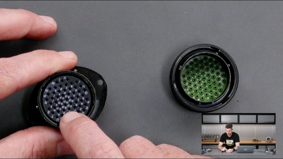
| 21:07 | Again really important that we specify this right because if you get this wrong, you can end up in a situation where your Autosport connector cannot be used together so again we'll get to our overhead, and I do apologise for the size of these but let's be honest, they are small for a reason. |
| 21:22 | So this is pretty self explanatory, here we have our pin, it's a male pin and here we have our female socket so we obviously need one side to be a pin and we need one side to be a socket. |
| 21:37 | Now there's no black and white here, there's no sort of rule on how this should be done. |
| 21:43 | Generally I find it better to specify that the bulkhead connector that bolts into the firewall, so in that case this one here, I normally would specify this to be a socket. |
| 21:58 | It means that if the harness has been disconnected and something is live, nothing can get in here, at least not easily, and short between two pins which could occur if we had the other side of the connector as the bulkhead. |
| 22:14 | So let's just have a quick look at this. |
| 22:15 | So this is our socket side so as you can see that is our 2 bolt, so that's going to be bolted to the firewall and this is what we're going to see poking out. |
| 22:24 | So again, very difficult if our harness is disconnected, nothing's going to get in there and short together. |
| 22:30 | You could imagine that if this was the part that was bolted to our firewall and we had all of our pins in here, if something did get in there, first of all we risk the pins being bent but also we get that situation where we could have something short together. |
| 22:45 | It is an unlikely situation but it is definitely a situation that we could find ourselves in. |
| 22:52 | So that's how we specify which is to be the pin and which is to be the socket side. |
| 22:58 | Next we have our shell keyways. |
| 23:03 | And this is something that in most instances, unless you've got a number of Autosport connectors using the same exact shell size right beside each other, we don't need to give too much thought to. |
| 23:14 | What we can see, again under our overhead shot is that these particular Autosport connectors are red or have a red band and that is the standard N keyway. |
| 23:27 | So it just means that any of those red keyways, they are compatible, if you get into that situation where you've got 2 side by side, you could inadvertently connect to the wrong one. |
| 23:37 | But if we come back over to our Autosport manual here you can see you can specify the keyway to be yellow, green, blue, orange or violet. |
| 23:46 | And basically that just makes sure that you can't accidentally connect the wrong connector up. |
| 23:52 | Also worth mentioning here that particularly in our current age of supply chain shortages, it's going to depend to a degree on what your supplier can get hold of. |
| 24:05 | Getting hold of the standard red keyway, normally not a big issue. |
| 24:09 | Some of the other coloured keyways can be a little bit trickier to get hold of and just so we can see what that looks like as well, this is of course one of those yellow keyways and again, a really good example of a special Autosport connector here, this one's for power distribution so you can see it's got 2 really large gauge studs as well as 3 additional heavy gauge contacts through that. |
| 24:36 | Alright at this point, that's essentially what you need to know, what you need to understand with the way an Autosport part number is written and that's what you're going to need to specify what you actually want to order. |
| 24:54 | However, we still need to actually understand how to decide on what that's going to be so I wanted just to go through a bit of an example here with the FJ40 harness that I've got in front of me and sort of go through some of the design considerations that we had with this. |
| 25:11 | So let's head back to my laptop screen and we'll go over to our FJ40 harness design Google sheet and there's a lot going on here, but I'll try and keep this simple. |
| 25:22 | What we actually start with is the ECU and this is nice and easy because the ECU has a defined connector, obviously the ECU manufacturer tells you what the connector is going to be and in this case we are running an 8STA so it's a Souriau part. |
| 25:39 | The 0, which we now know what that means, for the style of the plug and then it is an 1835SN so it's a size 18 shell, the contact arrangement is 35, it is a socket and it is the standard N red keyway. |
| 26:00 | Now also, we'll talk about these boots in a second as well but that's defined, we've got all of our pin outs for that, no big deal there but what I wanted to do is get to a point where we can actually make some decisions which is our bulkhead connector. |
| 26:13 | So we got to a situation where I think I had about 82 conductors that I really needed to run through the firewall and that gets a little bit tricky because 82 isn't a number that's going to be easily supported. |
| 26:28 | But it is also close enough to a number that is going to be supported so let's see how that works out. |
| 26:35 | So first of all, we already know from what I've said that with our engine harness, I'm going to be reverting by default to a 22 gauge contact and we've also talked about the only scenario really where that could be problematic which is our starter motor. |
| 26:51 | So we know what our wire gauge is going to be so let's have a quick look here and see in our catalogue what we could actually get away with. |
| 27:01 | And if we look at our size 20 shell, that starts with these two up here and then follows through to these ones here. |
| 27:15 | Well if we look at this particular one here, this is looking like it's going to be a really close option for us, the 20-35, it's a size 20 shell, that gives us 79 size 22 contacts so as I said, I think we had about 82, maybe it was 83 so we're close but obviously we're still over that so what can we do to get away with using that so that we don't have to maybe step up to using two connectors to get through the firewall? Well what we can do is actually consider sharing some of our pins. |
| 27:52 | So just scroll down through this, I'm not going to get too deep into the weeds with it but what we can do here, in the middle of our connector which interestingly the highest number in this case, pin 79 is in the centre of the connector. |
| 28:09 | What we've done is we've basically located all of our big cumbersome wires which are our two core shielded wires for the likes of cam position, engine reference, engine synchronisation and knock. |
| 28:24 | There's another good reason, just getting a little bit off topic but another good reason of doing this is that those make a really good core for our concentric twist to go across so that's what we've got in the middle here. |
| 28:34 | But what we've got here is each of these shielded cables has a shield, by definition, obviously there's a hint in the name there. |
| 28:42 | And we need to get that shield through the Autosport connector as well. |
| 28:46 | And how we do that is by using a solder sleeve to a shield drain and then that terminates in a single contact to go through. |
| 28:54 | What we've done here in this particular location here, let's just try and highlight that whole line. |
| 29:01 | That one there, shield knock and then we've got our shield for our reference and sync. |
| 29:09 | So basically I've shared, instead of having in that case 4 positions going through the firewall connector, we've just managed to pull that down to two so that was enough, by sharing those to actually get our pin count down to 79. |
| 29:26 | We are right on the absolute upper limit of that but at this point we now know that the 20-35 is going to be suitable. |
| 29:34 | So let's scroll back up. |
| 29:36 | So the part number that we've actually got here is our AS620-35SN. |
| 29:44 | So 6, you'll remember from our catalog, is a free plug, the other side of this is of course going to be our 0 part which is our 2 hole flange, so we can bolt it to the firewall. |
| 29:59 | Now the next part of it, our S & N. |
| 30:03 | So S, we already know that is a socket. |
| 30:06 | Now this actually flies completely in the face of what I just mentioned whereby conventionally we would specify the two hole flange part to be the socket. |
| 30:17 | In this case, and we'll get it under our overhead, we can actually see that I've used the sockets on the engine harness side. |
| 30:27 | So as I said, it's a guide, it's not set in stone, there's some good reasons why we would do it around the other way. |
| 30:34 | The only reason that I've done this is we happen to have the matching half of this connector already sitting on the shelf so rather than needlessly buying another connector body, I made use of what we have and of course I understand the implications in that, it's an in house project as well but just to put a little bit of context around that. |
| 30:55 | So that's how we can go about specifying, once we know basically what conductors are going to be going through and what size guage of wire we're going to need. |
| 31:04 | There is a little bit more information that is in the Autosport catalog that I wanted to go over as well. |
| 31:13 | Shortly we will jump into our questions so this is a great time to remind you, if you've got any, please start asking those now. |
| 31:21 | But before we do that, we'll look at the tooling that's required and the, how we decide what that's going to be. |
| 31:31 | So let's have a look here, again I'll just zoom in a little bit. |
| 31:36 | So contacts and tooling numbers. |
| 31:40 | So this is what we need to define what tooling we need to crimp this properly. |
| 31:45 | So basically what it does is it gives us for the Autosport range, the contact size, be it 22 gauge, 20 or 16, then it gives you the part numbers for the pins and the sockets. |
| 31:57 | Now typically when you're ordering the Autosport connectors anyway, they will come with the pins and sockets as required but there's going to be a situation probably where you do need to reorder so this way you know exactly what you need. |
| 32:10 | This is also going to come with an insertion and extraction tool. |
| 32:15 | Let's get one of those under our overhead here. |
| 32:19 | These are colour coded as well so in this case the green and white is for 22 gauge. |
| 32:24 | Yeah orange if you're doing 20 gauge for example so you can tell at a glance what they are. |
| 32:29 | So one half of this is for inserting and basically this allows you to insert the contact properly, make sure that it is clicked into place properly and the opposite side you can use to actually extract the contact if you've made a mistake or something of that nature. |
| 32:48 | They are pretty fragile, they do require a little bit of care but they are purposefully made fragile so that you'll damage the insertion and extraction tool, rather than an expensive Autosport connector. |
| 32:59 | Had a few people ask why these aren't made out of metal or something like that, that's the reason, we don't want to risk damage. |
| 33:08 | Next we have our crimp tool and generally the crimp tool that's the go to for Autosport connectors is the DMC AFM8 crimp tool which is this little guy here. |
| 33:23 | Probably if you've ever seen anyone building motorsport harnesses, you will have seen one of these already but the crimp tool on its own unfortunately is not much use, we also need a positioner. |
| 33:37 | And the positioner basically does exactly what its name implies, it positions the pin or the socket so that the crimp is going to be placed in exactly the right place. |
| 33:48 | So again we don't need to guess, the Autosport manual tells us what positioner to use for a pin or a socket for each of those sizes. |
| 33:56 | I'll show you one of those now. |
| 34:00 | This is a positioner and basically we open the AFM8, that clicks into place and again might be a little bit hard to tell but depending on your wire gauge you can also adjust the crimp tool so that you're going to get the correct amount of force being applied. |
| 34:22 | Basically it calibrates your crimp tool so that you're going to get a reliable crimp without undercrimping or overcrimping. |
| 34:28 | So that's probably one of the more common questions we get around using the DMC crimp tool is how do you know what positioner to use? You don't need to guess, the Autosport manual will tell you. |
| 34:41 | Alright now getting a little away from the specifics of the Autosport connectors but just something that is worth mentioning, you also are going to need a really good quality set of wire strippers. |
| 34:55 | So I would highly recommend, these are my favourite. |
| 34:58 | These are an Ergo Elite from Ideal. |
| 35:01 | So they've got a set of blades that are designed for the Milspec wire, Tefzel wire that we use. |
| 35:08 | There is also this optional little wire stop. |
| 35:11 | So this is just a little fence essentially and you can adjust it and lock it in place and basically then when you insert the conductor in it, you can butt it up against that wire stop and it just ensures that you're going to get consistent strip length for your wire. |
| 35:28 | You might be thinking well why does that really matter, does that really matter and the answer is that yes it does. |
| 35:34 | What we're trying to do is get a specific amount of strip length and let's just jump across to my laptop screen. |
| 35:45 | Basically what we want to do is make sure that we've got sufficient strip length so that we get full engagement inside of the pin or socket and we also want to make sure that when it's fully engaged we also have this little gap between the insulation in the back of the pin or the socket. |
| 36:04 | It's important that we have that because A, if we have the insulation butted hard up against the contact, we may not have that full engagement. |
| 36:14 | We do have a little inspection hole as well which I'll talk about in a second. |
| 36:19 | So that's one element, we might not have complete engagement and if we've overlooked that inspection hole, we don't really know how much of our conductor is engaged. |
| 36:27 | The other element though is that if the insulation is butted hard up against the back of the contact, then basically that's going to impart stress and strain as that wire moves backwards and forwards and vibrates so we want to allow that small amount of a gap there. |
| 36:45 | Obviously excessive, we could end up with problems so that's the range that we're expecting to see there. |
| 36:52 | 0.6 to 2.5 mm, I'd probably be more likely to be sort of around about 0.6 to 1 mm, that's kind of what I aim for. |
| 37:02 | So that is why it's really important to have a good quality set of wire strippers with a wire stop because in this case, 79 individual conductors that I'm stripping the insulation off, it's very difficult to get consistency on that number of conductors when you are doing it manually so you want to make sure that you have a consistent strip length. |
| 37:27 | Now I'll just head back across, there is also another manual here which is worth having a look at, so this is a Deutsch Autosport technical manual. |
| 37:40 | So this has a lot of information in it but it has some best practices as well. |
| 37:44 | So basically talks here about the sort of tooling that you're going to need. |
| 37:50 | Talks here about the strip length as well and that's probably a little bit more strip length than I would normally like to see but essentially gives you the idea of what you're trying to achieve so a really good place to sort of come and read through, understand the technicalities and get a little bit more knowledge on the best practice standards as per Deutsch's own recommendations. |
| 38:16 | Now one last thing I wanted to talk about was the boots that we use on the back of these connectors. |
| 38:24 | And again, if we come back across, I'll just shrink this down. |
| 38:31 | No I don't need to. |
| 38:34 | And over here we have boot termination detail, basically gives you a list of the diameters for the different shell sizes. |
| 38:44 | And you can use that in conjunction with the likes of TE or Hellermann's boots and basically work out here, so for example the H and H dimension there, so that's recovered and as delivered and what you can do then is basically look at that list there and basically work out what is going to suit your particular Autosport connector shell size. |
| 39:14 | You do also need to consider the dimension for our J, this will obviously shrink down onto our wire itself so there might be a range of different boots that will actually work with your contacts, your shell size but you may also need to consider what the diameter of your harness is that you're going to need to shrink down on as well. |
| 39:36 | Alright let's move on with some questions now, so this is a good time to ask any questions if you haven't already. |
| 39:53 | First question comes from Wedge905 who's asked, what are your thoughts on splitting a large gauge battery cable through an Autosport connector? Which would typically be 20 gauge wires through one Autosport connector for 150A total. |
| 40:08 | OK so if you're going to run a battery cable through, you would be using one of the special Autosport connectors that are designed for exactly that task. |
| 40:21 | I personally haven't done it. |
| 40:23 | There's nothing wrong with it, you'll find that being done. |
| 40:26 | But it is a very expensive way of getting your battery cable through the firewall. |
| 40:31 | There are some really nice solutions that we use such as the Radlok studs, those work really nicely at a fraction of the cost but absolutely you can run it through an Autosport connector. |
| 40:43 | I certainly would not be recommending that you break down a single battery cable into individual 20 gauge wires, that's going to be a hell of a mess, just about impossible to get a good result doing that and frankly just absolutely not necessary. |
| 41:01 | Wedge905's also asked, is it OK to crimp multiple wires into a single Autosport pin? No you should not be doing that. |
| 41:09 | They are designed to work with a particular conductor size. |
| 41:12 | You're not going to be able to fit multiple conductors into a Autosport pin anyway so yeah definitely not something you'd want to do. |
| 41:20 | If you need to do that, you're going to be doing that with a splice in behind the boot at the back of the Autosport connector itself. |
| 41:29 | Alright looks like that's all the questions we've got in there. |
| 41:33 | As usual, if you've got any further questions on this after it's aired, please ask those in the forum and I'll be happy to answer them there. |
| 41:41 | Thanks for watching and we look forward to seeing you next time. |
Timestamps
0:00 - Introduction
1:45 - Many different types within the Autosport range
3:00 - Focusing on the standard Autosport connectors today
3:30 - Choosing your wire gauge
5:08 - Doubling/tripling up contacts
7:45 - Working out how many positions are required
8:29 - Common wire gauge
12:34 - Understanding Autosport part numbers
24:55 - FJ40 project example
31:22 - Required tooling
34:41 - Booting options
39:54 - Questions


