320 | Introduction to CAD with Fusion 360
Summary
Fusion 360 is a popular CAD package at the hobbyist and professional level. In this webinar, we'll take a look at how to get setup and start designing with Fusion 360, take a basic tour of the software and discuss the pro's and con's compared to other offerings.
| 00:00 | - Hey team, it's Connor here from High Performance Academy and welcome along to this week's webinar. |
| 00:05 | So the topic today is going to be an introduction to CAD with Fusion 360. |
| 00:10 | So what we'll start with is just a basic conversation or discussion about what CAD is. |
| 00:18 | So for those of you who aren't familiar with CAD, obviously, well not obviously, it stands for computer aided design and that's basically exactly what it sounds like and it is a very broad topic that covers a lot of different areas but generally when it's being discussed, it's referring to 3D modelling. |
| 00:40 | So there's really, the way I see it, there's really a few key advantages to 3D modelling our designs and one of those main ones is to get the idea out of our head and onto the screen so we can create it virtually and that gives us a really good understanding of it and how it's going to work. |
| 01:03 | Rather than for example if we're fabricating something and we're kind of just making it up as we go, we can very easily get to a point where we're like oh this isn't going to work and we have to start from scratch. |
| 01:16 | Of course with CAD that's a lot easier, we haven't spent any money or time on materials, it's just a matter of moving back a few steps, making adjustments and going from there. |
| 01:30 | So that is one of the key points as well, we can make adjustments to our design, modifications to existing designs or any changes really quickly and if the model is set up correctly and references are correct then those can be automatically updated with any change we make to another part. |
| 01:52 | And we can do that all within the program before we spend any time or money manufacturing the part, that's really critical for something for example like a billet machined part that's made out of quite a big piece of billet, it's obviously going to be very expensive and the machining time costs a lot of money so being able to get it right first before we spend the money is critical. |
| 02:19 | And then from there, on that topic, another key advantage is we can then use our CAD model of our design to drive the manufacturing process, be it if that is creating technical drawings that we can give to a manufacturer to make our design off and check the measurements or if we're using the CAD model to drive CAM, computer aided manufacturing to drive a CNC machine basically to automatically make the part for us. |
| 02:53 | So in a motorsport application, how that's useful for us is obviously we can design parts and equipment for our vehicle or use around the vehicle and it allows us to understand how the parts will all work together in an assembly for example, how things will function together so we can get things that fit and function better the first time around rather than kind of taking an iterative approach that might be required when things are fabricated by hand. |
| 03:30 | Of course the CAD design can still, the design can still be done in CAD and then fabricated by hand afterwards and that also has an advantage of the prior planning. |
| 03:40 | Another key advantage of doing it, being able to design our parts with CAD programs, or being able to design our parts ourself really is availability of parts. |
| 03:56 | So often for motorsport applications when things become quite custom, a lot of the time there's not a bolt on application, a bolt on part specifically for our application so at that point we kind of need to take matters into our own hands and design the part or otherwise maybe we just think we can do a better job of designing a part that's already available or maybe we can do it ourselves and get it manufactured for cheaper. |
| 04:24 | So yeah that is the key advantages of being able to learn CAD and use it for motorsport. |
| 04:32 | So moving on now to Fusion 360, what is Fusion 360? It is a CAD program that's focused around 3D modelling of mechanical parts and it's offered by Autodesk and Autodesk is the company who also offer Autodesk Inventor and AutoCAD which are two very big CAD programs that have been around for quite a long time, a lot longer than Fusion 360. |
| 05:01 | So Fusion 360 is kind of the newer offering by Autodesk at more of a hobbyist level than the other ones, a lot more expensive and at what I'd call a professional only level. |
| 05:14 | Although Fusion 360 is also used at a professional level as well but it is more targeted to small businesses and hobbyist kind of level as well. |
| 05:28 | And in that way, it's been designed to be more user friendly as well which is an advantage for us just getting started in CAD. |
| 05:40 | So it is a 3D modelling program but it also features a lot of other tools around CAM, computer aided manufacturing as well as simulation and generative design and some other areas. |
| 05:54 | So a lot of other CAD programs also have those inbuilt tools as well and some don't. |
| 06:01 | Fusion 360 has a good range of them. |
| 06:07 | So one of the key points with Fusion 360 is there is a free version that is Fusion 360 for personal use. |
| 06:16 | If we just jump onto my laptop screen, I have the webpage open from the Autodesk site here. |
| 06:24 | If you just searched Fusion 360 for personal use, this is one of the first ones that pop up. |
| 06:30 | And here you have a really clear comparison between the free and paid version of Fusion 360. |
| 06:38 | So for the design and 3D modelling which is kind of the key part we're interested in, a lot of the tools and functionality is really the same here. |
| 06:51 | Where we do have some limitations is in these other areas here so import and export file types, documentation, things like that. |
| 07:04 | So one of, some of these limitations of the free version may or may not be a problem to you. |
| 07:12 | It really depends on what you're working on. |
| 07:15 | The paid version of Fusion 360 as we see down here, they've got a bit of a sale on at the moment so that's around $500 USD a year and that is although significant, still on the a lot more affordable side of the spectrum when it comes to CAD programs or specifically more powerful CAD programs. |
| 07:43 | But yeah we'll come back to this page in just a moment. |
| 07:49 | Firstly we'll just talk about some pros and cons of Fusion 360. |
| 07:53 | And these can kind of be viewed either way so first of all, Fusion 360 is cloud based and that means that all the files are stored online but the advantage of this is you can access the files from any device so for example I use a laptop while I'm working at home and I use a desktop at work, different computers and I can access the same files by just opening the application. |
| 08:24 | Fusion 360 has a lot of features, it is quite a powerful program, especially when you get used to it. |
| 08:33 | You can basically model whatever you'd need to model for a motorsport application anyway. |
| 08:40 | And the other thing is Fusion 360 is focused around what's called a top down modelling approach. |
| 08:50 | So basically what that means, I have another image here on my computer. |
| 08:58 | So top down modelling basically means that our design is in one single location, we can have one single design file and inside that we can model all the components in assembly from one single location and model them in the context of the other parts. |
| 09:26 | Whereas more of a bottom up approach like what Solidworks for example is more focused around, the parts are modelled individually and then bought together in an assembly and that has its benefits especially in terms of revision control which is important in professional environments but it can make the process a bit slower if you're working in an assembly and you need to go out of the assembly to change an individual part and then bring it back into the assembly to make updates. |
| 10:04 | Obviously in Solidworks there is some ways to work around this and in any case with a lot of these programs, you can take a top down or bottom up approach, it just depends what the program is actually kind of designed around or focused on using. |
| 10:23 | So Fusion 360 uses this top down approach and once you get used to it, it is very effective and it does speed things up quite a lot so as I see it, that's one of the advantages. |
| 10:34 | So if we're talking about disadvantages, the cloud based aspect to it could be a disadvantage because you do need an internet connection to work and save your files although you can switch to offline mode which I'll show you how to do in a moment and work from there. |
| 11:00 | So it's not a deal breaker. |
| 11:05 | Fusion 360 is an application so you download it to your computer. |
| 11:10 | As opposed to something like Onshape which we'll discuss in a moment which is browser based so you just access it through the internet. |
| 11:21 | So you download it, this could be an advantage or a disadvantage depending on how you look at it. |
| 11:30 | You have to use the storage on your computer to save it but you can work offline as well. |
| 11:40 | One of the key limitations to Fusion 360 is with the free version, so the free for personal use version and the key disadvantage around this is that you can only have 10 active and editable documents at one time. |
| 11:59 | And again this may or may not be an issue for you, you can save a lot more documents than this or designs but you need to basically toggle them between active or non active and then also a lot of the features, the more advanced features are not available in the free version. |
| 12:21 | So the free version does have its limitations but really depending on how you look at it, comparing that to the paid version as well, if you compare either of those versions to something like Solidworks which has all the functionality built into it but is 10 times more expensive, it's easy to see that at $500 a year for the Fusion 360 paid version, that's an advantage to have all of that functionality in that package. |
| 13:00 | So depending on what you're comparing it to, the cost side of things is an advantage or a disadvantage if you compare it to something like FreeCAD for example which is free, anything involving cost is going to be a disadvantage. |
| 13:19 | On top of this, so the price has increased for the paid version over the last few years and it'll probably increase more in the future, that's just something to be aware of. |
| 13:32 | The free version has obviously stayed free but sometimes when new features are added to the program they are only available on the proprietary version so just something to keep in mind. |
| 13:48 | The other thing to point out is Fusion 360 is subscription based and that basically means you download the application but you pay it on a yearly basis or maybe monthly, it's not something that you can just download, have on your computer and use for life, it's not a one time thing. |
| 14:09 | But that is kind of the way a lot of programs like that, if anyone's familiar with the Adobe Creative Suite, a lot of these things have gone the same direction. |
| 14:19 | So if we just compare it quickly to some other programs, start with something like Solidworks which is one of the main go to professional CAD programs and a lot of what I'm going to say here is also applicable to Inventor and Creo Pro E as well, they all kind of fall into the same category, although different in their own ways. |
| 14:42 | These are non cloud based programs, so all the files are stored on your computer as opposed to Fusion 360 being cloud based, storing the files online. |
| 14:53 | Solidworks for the standard license is about I think six to eight times more expensive than the paid version of Fusion 360 per year. |
| 15:04 | And then there's a premium version which you basically double that price again so it's significantly more expensive and probably out of the budget for a lot of home enthusiasts who are just using this on their own projects. |
| 15:19 | Fusion 360 is significantly more affodable in that way. |
| 15:24 | Solidworks, Inventor and Creo however are very powerful programs, they've been around for a long time and had a lot of development in them. |
| 15:35 | This can be good or bad, if you're new to CAD modelling, it can be kind of overwhelming, Solidworks itself is quite a user friendly program, Creo Pro E on the other hand is not so much. |
| 15:50 | But if you were to compare them to Fusion 360, yes they are more powerful. |
| 16:04 | So another thing with Solidworks is you download the program to your computer and it takes up a significantly larger amount of space, I think it's about 40 GB so a lot more than Fusion 360 which I think is four. |
| 16:21 | Moving onto another program, Onshape, which we discussed before is what I would say is the most comparable to Fusion 360. |
| 16:29 | It's also a cloud based program but it's also browser based so it's not an application you have on your computer, you access it through your browser. |
| 16:38 | There isn't as many features and tools as Fusion 360 as Onshape but it does still, especially around simulation and computer aided manufacturing, so those more advanced things, Onshape kind of loses its edge to Fusion 360 in that case but working with assemblies, there's some really good tools in Onshape and it is maybe arguably better for working with assemblies than Fusion 360. |
| 17:13 | There's a free version as well and the paid version for Onshape starts at $1500 USD per year I think so it is more expensive than Fusion 360 for the paid version. |
| 17:27 | And the key point here is that the free version with Onshape only allows you to create public data so that means that anyone could find and access your files, they can't edit your files, it's a read only thing but if you are doing something that's very sensitive and you don't want it getting out there, it being leaked, that could be a bit of a deal breaker for you. |
| 17:55 | Of course though for someone to find it, they have to know it exists so it's not too big a problem. |
| 18:01 | We'll move onto one last CAD program and that is FreeCAD and as the name kind of explains, that is free. |
| 18:09 | And that is a program, an application that you can store the files locally on your computer, so not cloud based, it also has some good CAM and simulation functionality as well. |
| 18:28 | However FreeCAD is opensource and arguably that means that it is less stable than Fusion 360, there's also not a big company standing behind it so the technical support is obviously not as easy to get as Fusion 360 basically and the online community for FreeCAD is a lot smaller than that of Fusion 360. |
| 18:57 | Fusion 360's a very popular program and that means quite a lot if you're trying to figure out how to do something to be able to find information on it, find courses like ours of course and discuss it online with people, that is a big help and that is an area where Fusion 360 definitely has an advantage over something like FreeCAD. |
| 19:22 | So one of the key questions we get when we made our course which uses Fusion 360 for a lot of the examples throughout the course, is why did you use Fusion 360, why didn't you use this program or this program? And I think I've covered some of the points there of why we chose Fusion 360 since it is available for free, there is a free version, it's very popular and a lot of people are using it, it's user friendly, it has a good amount of tools. |
| 19:58 | But the key point here is that the best program for you to use is the one that works best for you, it really doesn't matter at the end of the day. |
| 20:07 | A lot of the functionality inside a CAD program is the same from program to program, a lot of the tools are called the same things. |
| 20:17 | The general ideas around the modelling are also the same. |
| 20:21 | If you can, if you understand CAD properly and you can use one program, you can definitely use any of the other ones, sometimes it just takes a few hours or a day or so to adjust to the differences before you get really fast with it but it's definitely a transferrable skill and just because you can use Solidworks, doesn't mean you can't use Fusion 360 or the other way around, you can transition between all of them once you understand the fundamentals. |
| 20:51 | So moving on, we'll get into my laptop and into Fusion 360 and I'll give you a quick look around and then we'll move toward modelling something a little bit later on. |
| 21:02 | So starting in Fusion 360, we'll start at the top right corner over here, so here we have the usual account settings, preferences, things like that and we'll come back to these preferences here in just a moment to discuss some changes that I like to make to make things a little bit easier. |
| 21:26 | Here we have a help tab, we can search tools and things from here to find them quickly, there's also some learning panel and things like that to get some help inside Fusion 360 if you might be stuck on something. |
| 21:41 | Notifications centre, not too important, basically if there's something loading, it's just, something that we're exporting, that might show up here. |
| 21:52 | Job status, same kind of idea, at the moment this is showing that a new Fusion 360 version has come out so I can update it from here and this is where I switch to working offline or online if I do or don't have internet connection. |
| 22:08 | This next tab along here, is the extensions tab. |
| 22:15 | So this is a point about Fusion 360, some of the more advanced features are still not available even with the paid version. |
| 22:28 | It doesn't give you access to all of the advanced features, for example if you're doing simulation, FEA, you can create a study, you can work through it but when we actually want to solve the study, that can cost extra money and that is basically what the extensions are around. |
| 22:47 | You can pay for a subscription to an extension, so you can have unlimited access to it, for example for a year, or you can use the Fusion 360, they kind of have a currency set up, I think it used to be called flex tokens and now it's called cloud credits or something like that and it's just basically their currency, you buy some cloud credits and then you can use those to pay for things as you go, if for example you only wanted to do one simulation a month, there's no point paying for a yearly subscription to it, that's only beneficial if you're using it all the time. |
| 23:27 | So that's the extensions there, and if for example we click into here, you can see that same little power plug looking icon over some of these and that's really just showing that to use that tool, you need the extensions, so we'll come back to that soon anyway. |
| 23:47 | And we'll move on a bit for now. |
| 23:51 | So opposite corner, far left top corner, we have the data panel and this is basically where all our designs and files are located and we can arrange these into different projects and it's basically just your file management system and in my case I'm using the proprietary version of the software but if you were using the free version, this is where you can toggle your designs between inactive and active and editable documents and this is also where you come to find your designs, open them and maybe upload designs that you might have downloaded or sent to someone else or something like that, that's all done from within here and there's also a teams tab up here where you can collaborate with other people on projects as well. |
| 24:48 | So moving on, that's the data panel, we'll look at the file tab next. |
| 24:58 | This is fairly standard for a file tab, what you'd expect to see, open, save, export, all that stuff, but this is also where you come to create new designs, that or this little plus icon over here to the right. |
| 25:14 | So fairly standard there, we'll move on quickly from that. |
| 25:17 | Next is the workspaces. |
| 25:20 | So workspaces, we're generally, when we're 3D modelling, we're working within the design workspace which is the one that you see at the moment. |
| 25:28 | But if you want to do generative design for example, you'd come here, click on this and it would bring up this new tab where you can start working through a generative design study and the same thing goes back here for simulation, if you'd modelling something already and then you wanted to work, so a simulation study, for example a stress analysis, this is where you would access it from. |
| 25:57 | There's the other key one to consider here, so that's generative design simulation, computer aided manufacturing, so that's all done from there, making tools paths and stuff like that to control the CNC machine and then the drawing one down here as well, where we can start to create a new technical drawing from the design that we have modelled. |
| 26:19 | That's available there or also under the file tab as well, new drawing. |
| 26:26 | So moving on, so that is our workspaces. |
| 26:29 | And other than that we have our toolbars along the top here so that's where we see solid, surface, mesh, sheet metal, so on. |
| 26:38 | So inside these toolbars are our tools obviously and that is what we use to do the modelling process. |
| 26:46 | So this is where we can basically create 2D drawings, profiles and turn them into 3D bodies using these tools, modify them and do basically all sorts from here. |
| 26:59 | In these toolbars we have a range of different toolbars for different types of models that we're creating so basically they create different what we call bodies in CAD. |
| 27:11 | So starting with the solid one, solid modelling, creates solid watertight bodies. |
| 27:22 | So sheet metal bodies are also the same in this regard so this is like, if you extrude a 3D object, that will be filled in and you can shell it out and cut out internal parts of it but it creates a solid body basically. |
| 27:42 | And a lot of the tools in this tab, these are ones that you commonly see used across every CAD program, something like up here at the top, extrude, revolve, sweep, loft, that is basically the same as what I've seen in every CAD program I've used. |
| 28:02 | So same for Fusion 360, Solidworks, Creo, you'll see those tools. |
| 28:08 | Sheet metal modelling, oh we'll move over to here, sheet metal modelling has a lot of the same tools in it but it has tools that are more specific to the manufacturing processes you use with sheet metal parts. |
| 28:23 | So bending the parts, forming them, things like that. |
| 28:27 | And yeah so some of the same tools from the solid modelling toolbar are in here and other toolbars as well but the key ones being these sheet metal specific tools like bending and unfolding and things like that. |
| 28:50 | Moving on from here, sorry just keeping an eye on my notes, surface bodies is the next one. |
| 28:59 | So surface bodies compared to solid or sheet metal bodies are bodies that are infinitely thin, so it just creates a surface rather than a solid thick object. |
| 29:12 | So this is really beneficial when it comes to modelling complex surfaces so surfaces with complex curves, so if you viewed a surface from any different direction you'd always see the curve to it. |
| 29:29 | It just gives you a bit more flexibility in that aspect compared to some of the solid modelling tools, however because we can't manufacture something that's infinitely thin. |
| 29:41 | When it comes time to actually make the part, we need to thicken it or use another tool to convert it to a solid body, to then move onto the manufacturing process. |
| 29:53 | But these can be really beneficial for creating something like exterior panels for a vehicle, something like an over fender, fender flare or something like that that has quite a complex curve to it and very thin compared to its overall size, surface tools are really useful there. |
| 30:17 | Moving onto the next tab is the mesh toolbar. |
| 30:22 | Meshes is something that, that is the file that we get from a 3D scanner and it's a file that we give to a 3D printer and it's basically, it's similar to a surface body where it's just a shell but it's made up of many many little elements that are divided by edges and modes and basically makes up an entire body which is called a mesh. |
| 30:57 | And there is specific tools in here to working with meshes and then again after you finish with this, you can either take it from here and 3D print it or you can convert it into a solid body and work with it with your solid toolbar as well. |
| 31:17 | And there's a few other tabs here, plastic modelling, it is very very similar to solid modelling and then other kind of tools that are more suited to working in larger companies where you need to control the revisions of parts and assign actions to people basically, and get parts peer approved and things like that. |
| 31:47 | So we'll move on from there. |
| 31:51 | Back to the solid modelling tab, so we'll start with the construct toolset here. |
| 31:58 | So this creates datums using the construct drop down here and a datum could be a plane, a point or an axes and they are really just imaginary, not parts, they're imaginary features that we can use to model the rest of our design basically. |
| 32:23 | So there's a range of tools here and they're all fairly self explanatory and of course if we hover over them we get a bit of a description of what we can, how we can use it to the side of that. |
| 32:41 | So again create these planes or axes or points and we can use them to model other parts but they're not really included in the final solid bodies. |
| 32:59 | From there, moving onto the create tool set. |
| 33:03 | So this is where, what we use to create our 2D sketches or our 3D bodies. |
| 33:10 | For example we would create a sketch and that's our 2D drawing, we can also create 3D sketches as well though and then we would extrude from that, a 3D body, which I'll show you how to do in just a moment and then once we've used our creation tools and we have a 3D body, we can use the modify toolset to make modifications to it and there's a range of different ones here which again I'll show you soon how to use. |
| 33:42 | There is, with the create tools and the modify tools, quite a lot of flexibility with the order that you use them in as well as the settings and preferences inside the tools so we have a lot of flexibility over what we can model, we can basically model whatever we can think up. |
| 34:01 | The key thing to keep in mind here is the manufacturing process, we don't want to design a part where we can't get it manufactured for whatever reason so we always need to keep the manufacturing process in mind to make sure our, we can actually make our design at the end of, designing it, modelling it. |
| 34:22 | Moving on, so in the middle here we basically just have our model space which is where we'll be able to visualise the model and we'll get something in there in just a moment and in the top right corner here we have our origin basically, this shows the orientation of our model so if I click and drag on the middle mouse button, you can see that that moves and when we have a model in there, that'll make a lot more sense but we can also click this and move our model around so that just basically shows that and there's a few more settings here if we right click, change between perspective and orthographic views, things like that. |
| 35:10 | Over on the, down the bottom of the screen, we will have our timeline. |
| 35:16 | Again we'll see this soon, and the browser here. |
| 35:19 | Those are the other important parts that we come to quite a lot and when I model something, it'll make a lot more sense so I'll show that there. |
| 35:28 | And then we also have a bunch of settings for how we view a model down the bottom here. |
| 35:33 | So that is, oh before we move on, I will just show you in the preferences, some of the key settings that I like to change just to speed up the modelling process for what I am used to. |
| 35:49 | So one of the first ones I do here is the default modelling orientation, I change it to Y up rather than Z up and if you look over here, you'll see the Y axis, X axis and Z axis and I am just more used to, 'cause I've used Solidworks the most, the Y axis being in the vertical position, it just makes it easier for me but it's whatever suits you, the Z axis, Z up orientation is more suited to when you are using the CAM functionality, computer aided manufacturing, so when you come to make the tool paths and stuff, having the Z axis in the vertical position does save you a bit of time but it works either way, it doesn't really matter. |
| 36:35 | Another one that I change here, the pan zoom and orbit shortcuts. |
| 36:39 | Like I said, I'm most familiar with using Solidworks, these basically just change what buttons on the mouse and on the keyboard you need to click to move the model around. |
| 36:52 | I like to have it on the Solidworks ones 'cause it just makes it faster for me to navigate through the program and move my model around so that's where you do that. |
| 37:02 | Another one, so if we go into this side over here and find the drawing tab. |
| 37:10 | Another one I like to change in here is just changing, I use the standard iso standard and I change the projected projection angle to 3rd angle projection. |
| 37:22 | If you're not familiar with technical drawings, don't worry about that for now, we won't get into that but if you are and you understand first and third angle projections, I just change that there, again I like to use 3rd angle projection but I like to use iso for the standards as well. |
| 37:46 | Sorry. |
| 37:49 | Anyway so, that's a few changes I make. |
| 37:52 | Before we move onto modelling something, I just wanted to discuss a few important points that as you work through the, learning CAD, you might hear these come up in courses or things like that. |
| 38:07 | So parametric modelling is probably the first one and you'll hear this for example in the name Creo Parametric, the commonly used CAD program. |
| 38:19 | So parametric modelling basically just refers to the way that our model is created, so it's created using parameters and it's controlled by the parameters and that means that we have a history of the features and we can go back and change them and edit them very easily and this is probably, for the type of modelling that we do, especially in motorsport parts and mechanical parts, this is really the most suited and it's the system that most of these programs, Solidworks, Inventor, Fusion 360, they all basically work on parametric modelling. |
| 38:59 | Moving on from here, the alternative is direct modelling and this is a little bit more free and flexible and this is basically means that the model is geometry based rather than feature based and don't worry if that doesn't really make too much sense but basically what it means is you can push and pull surfaces of the model and really mould it like clay so this really lends itself to very quickly creating a concept of a design but the problem is you can't then go back into the history and modify something that you'd already done and have it all update to how you want it so it's fast but it's not really well suited to something where you're making modifications and revisions. |
| 39:46 | And that brings me to another point, back on the computer screen here that I wanted to discuss and this is this create form tab tool in our solid toolbar. |
| 39:58 | So if we just jump in here, this is a newer kind of feature to have in Fusion 360 and it basically lets you do, model organic shapes, the ones that we'd see from something like generative design if you're familiar with that and kind of push/pull and move points around in a more free fashion. |
| 40:25 | I think it's referred to as t spline modelling. |
| 40:32 | So yeah you can get a really organic shape out of here that can work really great with fluid flow or something like that and it's a lot more flexible. |
| 40:44 | So as you come in here and you use the tools, it will follow kind of a parametric thing where you get features on your timeline but then as you finish the form in the timeline, that history won't be captured anymore so it's kind of like creating a direct, it's like direct modelling inside of a parametric modelling system if that makes any sense. |
| 41:12 | Anyway, we will move on from that. |
| 41:15 | So if you have any questions at this point, it's a good time to start entering them into the chat and I'll get to those at the end just after we've done a bit of a demonstration of modelling something. |
| 41:30 | So swap over to some photos quickly, what I'm going to model, because it's a fairly simple thing to model quickly, and I can take two different approaches, is these two different shift knobs. |
| 41:45 | So these are kind of popular, classic ones from Nismo that a lot of people have seen. |
| 41:53 | So we've got their aluminium version here which is kind of a cylindrical design with a bit of a taper on one end and then the duracon one here which is more of a obscure rounded shape. |
| 42:10 | So we'll start with these and I'll model each of them quickly, I'll use two different methods just so you can understand the different process you can take to model something that's very similar. |
| 42:22 | So jump then back into Fusion 360 and where to begin on something like this when you're just getting started on CAD can seem a little bit ambiguous and not make much sense but as you get more experience and you understand the different ways you can model things, it starts to become more obvious of where to start. |
| 42:41 | So we'll start with the aluminium shift knob and what we'll do is we'll create a sketch and we'll do that on the top plane here, also known as the ZX plane because it intersects the Z and X axes. |
| 42:57 | So if we click that then it takes us to look directly at that plane and we'll start by just sketching a circle here on the origin point which is in the centre of our model space and I'll just enter 30 there, I'm working in millimetres. |
| 43:16 | So our circle will have a diameter of 30 mm and it's centred on the origin. |
| 43:22 | And that's all it's going to take for that first sketch. |
| 43:26 | From there I can move into the extrude tool which is probably the most common 3D creation tool that you'll use in CAD and I can just drag that 2D sketch up into a 3D body by 40 mm or I could enter 35 or 50, or 40, 40 there. |
| 43:54 | And that's just going to create a new 3D body from that and I'll hit OK. |
| 43:58 | So now there we have our first 3D body and I'm just using my Solidworks orientation setup on my mouse, clicking the middle mouse button and dragging and moving it around and you can see the views move here with it. |
| 44:14 | So from here, that is the main cylindrical part of the body and the next bit I'll do is the taper bit. |
| 44:21 | I'll click the extrude tool again and I'll click the bottom surface profile and I'll just drag that down say another 30 mm but this time I'll put a taper angle on it of -5. |
| 44:35 | So it just tapers it as it pulls it down and then the operation here will be set to join rather than new body or cut or anything like that, so that joins to the existing body that we already have and I'll click OK to do that. |
| 44:52 | From here, the next point is I'm going to create the threaded hole in the bottom of the part. |
| 45:02 | To do this I actually need a point in the middle on the bottom, so I just clicked to sketch on that bottom surface and what I can do is actually, we'll go the dropdown here, project and include this surface and I'm basically just trying to make a point in the middle of this surface so that's what I've got there. |
| 45:25 | I can finish this sketch, I can click the hole tool, select that point and this has made the hole too big so it's going right through the walls of the part but if I change the hole type to a tapped hole, with for example a flat bottom, and then I can come down here and change between different thread types so M12 x 1.25 I think is pretty standard for this. |
| 46:01 | And I can drag that up a bit and that red is showing where it's cutting into the part and it's got the threaded hole in there. |
| 46:10 | And now that is the threaded hole in the bottom to thread onto the shifter. |
| 46:15 | And just to finish off the part, I use the fillet tool which just rounds the edges on the top, for example 2 mm here and maybe I'll round this here at something like 50 mm. |
| 46:31 | And that basically finishes that model with those rounded edges and if I don't want to see those lines around the tangents, I can do that and that one's there done. |
| 46:46 | So down here we can see, we don't need that, the features or the processes I used in the timeline to do it, that was that sketch, extrude, extrude, sketch, hole tool and the fillet tool to round the edges. |
| 47:03 | So I can go back at any point and change this, for example, to 35 and that is basically, explains parametric modelling, go back and change that parameter and it updates the rest of it all to match that 35 mm measurement. |
| 47:22 | Up in the browser here, we have our one solid body and we also have a list of the sketches we use and can toggle the origin point on and off as well. |
| 47:35 | So I'll move on and I'll model the duracon style shifter. |
| 47:43 | So this one, I won't use extrudes, I will use a revolve because the shift knob is basically the same profile around a vertical axis that goes through it so it lends itself nicely to the revolve tool but this will make a lot more sense in a moment. |
| 48:03 | So again I'll start with a sketch and I'll sketch on the front plane here, also known as the YX plane, XY plane and I will again start with a circle, we'll say 40 mm diameter centred on the origin point, of course it doesn't need to be centred there. |
| 48:25 | From here, I can draw a line directly through the centre of it, that'll snap to vertical. |
| 48:36 | Then I can come out a bit here, up on an angle and over to here. |
| 48:47 | So what we see here, I'll just delete this for a moment so I can explain it. |
| 48:52 | With our sketches is we have constraints and basically what we're aiming for is our sketch to be all the profiles to be showing in black and that basically means that that part of our sketch is fully defined so we've defined, for example the diameter of the circle and where it's located so nothing about that is undefined or it can't be moved, or anything from that point, it couldn't be anything other than a 40 mm diameter circle centred on the origin. |
| 49:28 | However for example this vertical line here, I can drag it around because it thinks it's vertical which is what this constraint here is but it doesn't know where in space it's supposed to sit so if I use the coincident constraint here and I click that in the origin point, then it knows it has to go straight through that and it terminates on the top of the circle, comes down here. |
| 49:55 | So what we're trying to work towards is having the entire sketch shown in black. |
| 50:00 | I'll move on and get the rest of this worked out. |
| 50:04 | So this line here needs to be tangent to the circle, if you're not familiar with what tangent means, it basically means that if a line will touch the side of a circle, but if extended any further, it won't intersect the circle. |
| 50:20 | So it just will go off the wide of the circle again so it just touches the side of it. |
| 50:26 | So that constraint has been applied between this line and the circle. |
| 50:32 | And we also need to specify where the bottom line is relative to the origin for example, which could be, I'll call it 40 mm. |
| 50:46 | And from here we'll just round these corners, say two and two. |
| 50:57 | We'll make it three actually. |
| 51:00 | And then to make these bits of the line go black, I can just add 15 and we'll go 15 again for this. |
| 51:13 | And this one also needs a height. |
| 51:16 | This can definitely seem a bit complicated and take a little bit of getting used to, of understanding what a sketch needs to be fully defined by the more experience you get with it, the quicker you can do it and look at something in your head, understand how it's not fully defined and add those to it. |
| 51:34 | The reason we want to fully define it is just to avoid it accidentally moving and we might not notice it and then all of a sudden we've got other errors in our model and we don't understand why. |
| 51:48 | This is kind of like the best practice to lock everything down so it can't move. |
| 51:52 | Can use the trim tool here just to delete the parts we don't want and then we have our enclosed, closed loop profile here, it's actually a very light shade of blue to show that we can use to move on. |
| 52:08 | Before I do that, what I'll do is I'll actually model the hole in this as well so basically that'll just look like this, this will make more sense in a moment. |
| 52:22 | 12 mm hole for an M12 hole, half of that will be rotated around the thing so we'll make this six for now. |
| 52:33 | Again this will make more sense in a moment and this will be the depth of the hole which we'll leave it about 25. |
| 52:41 | I can finish the sketch there and then move onto the revolve tool. |
| 52:44 | So select the revolve tool and then just select the profile I want to revolve about an axis, which the axis will be the vertical one through here, so I can either choose the Y axis or just this vertical line will work. |
| 53:02 | 360°, revolve, so if it was 180 it would just be half of it but we want it to be 360° for the full thing and new body 'cause we don't have any other ones and there we have our part, I'l just turn the edges on again so it's easier to see, that looks like our shift knob. |
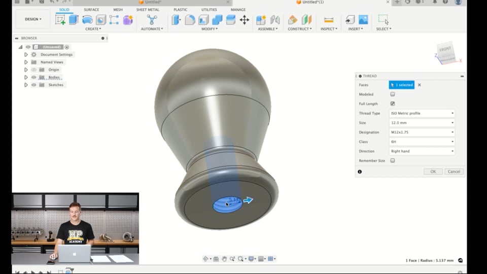
| 53:27 | So the only last thing here to do is add some threads to the bottom here and if we click that hole, it recognises it's a 12 mm hole and it applies a thread to that and we can change it again to the 1.25 pitch we had on the other one and there we have it. |
| 53:48 | Rather than a fillet on this one, I'll add a chamfer to the bottom edge of 1 mm as a lead in to that thread. |
| 53:57 | And that is that model for the other shift knob. |
| 54:04 | So similar thing, just modelled with a different approach. |
| 54:07 | And there's no right or wrong way to do it, I could have used a revolve for the first one as well, it's just whatever works out best in the end is more stable to modifications, most efficient, there's no right or wrong way, it's just what works for you and the more experience you get, you'll find more efficient ways to do things and ways that you like to model, might just be different to someone else. |
| 54:35 | So that's two different approaches. |
| 54:37 | From here, we could then move onto, for example, if I go to the mesh tab and go export, 3D print, I can then send it straight to the UltiMaker Cura program which is a slicer for our 3D printer that we have and I could 3D print this part, probably within an hour or two so you can see, 5 minutes to model, an hour or so to 3D print it if we wanted it to be 3D printed and then we have the shift knob, so pretty quick turnaround really. |
| 55:17 | Maybe the 3D print would just be the prototype or it could be the final part for a shift knob, 3D printed one would be fine. |
| 55:24 | So, or from there we could go to the manufacture workspace and for example if we had a CNC lathe, we could produce a G code toolpath to make this part from there. |
| 55:40 | Or make a technical drawing, send it to a shop where someone would make it themself on a lathe as well. |
| 55:48 | So that basically wraps up the lesson and I'll move into answering some questions. |
| 55:58 | If there are any. |
| 56:02 | OK so I'll start with this one from Diamond Star Works. |
| 56:07 | So advise on best methods of using picture inserts or multiple picture inserts to accurately recreate parts. |
| 56:15 | So this is like what we were talking about at the start in the pre show when we were talking about using the canvas for the valve cover design. |
| 56:23 | So using pictures in CAD, in Fusion 360 it's called canvases and we can use 2D pictures to basically use as a reference to design around. |
| 56:35 | My advice on it really starts from the stage of actually taking the picture so it depends, if you were taking the photo on your, if you were taking the photo to use rather than using something like a PDF drawing or a scan or something like that, you need to take the photo in a way that it minimises the distortion that you get with the camera lens, so you really need to take it straight on, not from any angle. |
| 57:06 | From further away is good, the closer you get to something, the more distortion you get and the higher the focal point of the lens you use, for example, if you're using your iPhone with three lenses, you want to use the most zoomed in one from as far away as possible, so you still get the part in the picture. |
| 57:32 | And that will give you the most true to shape basically profile to copy around. |
| 57:38 | When you go into Fusion 360, I'll just jump back into my laptop again here into Fusion 360 and go to the solid modelling tab. |
| 57:50 | I'd also recommend the picture file being a PNG image because sometimes when I've been importing JPEG files, it will scale it in different ways on the X and Y axis, I've found that PNGs tend to hold their shape a lot better. |
| 58:07 | We go insert here and canvas and then we can find, for example, yeah strut tower front view here, this would be a good one. |
| 58:26 | And then apply it to a face which would be this plane, I'll just hide the model for now. |
| 58:33 | And it will bring it in. |
| 58:40 | Yeah and then from here, we just have it centred here and this is an image looking straight at a strut tower in the FD3S RX7. |
| 58:51 | So from here it's in, we've got it on whatever plane we want and the key point here is to calibrate it so this will scale it to the correct size, so we need to take some measurements that we can copy in this when we're actually taking the photos, or in the engine bay, need to measure something to understand something, we can use to scale it. |
| 59:14 | So if I click calibrate, for example if I knew the distance from the top of this stud to the top of the strut tower here was 20 mm and click that, it'll scale this up, so now it is the correct size and basically from then I could sketch on that plane, oh maybe not, oh yeah sketch on that plane and use that as a reference, for example to design something like a strut tower brace or something like that. |
| 59:49 | Yeah canvases can be really useful for that. |
| 59:52 | So that's my advice on using those canvases. |
| 59:56 | The other way you could do it is if you had a technical drawing. |
| 01:00:01 | For example the photography side of things doesn't matter then. |
| 01:00:06 | If you have a PDF of a technical drawing you can also bring it in, apply it to a plane and then sketch around things as well that way. |
| 01:00:15 | So that's another good use for it. |
| 01:00:19 | Look back at the questions. |
| 01:00:23 | So Sergio says, if I wanted to highlight a moving part like a bearing between two static parts, how would you do that? Hope that makes sense. |
| 01:00:35 | So if you wanted to highlight it just for a visual kind of thing you can always come into the design file, I'll just hide that canvas again. |
| 01:00:50 | And what you can do is hit A or actually I'll do it this way, right click on a body and hit appearance. |
| 01:01:00 | And this will bring up the appearances tab and from here, I can basically have a range of different appearances in this design. |
| 01:01:12 | So for now the Fusion 360 thinks that the model of the shift knob is made out of steel and it has its own colours, being the grey colours applied to that. |
| 01:01:27 | If I just duplicated this, if I had multiple bodies in the design, I might want to do this. |
| 01:01:33 | And right click and edit it, I can for example change the colour to red, hit done and then I can just drag that onto that body. |
| 01:01:45 | So if you had the bearing between two things and you just wanted to change the appearance of it for that reason, that would be an easy way to do it, just change the colour of it and that way, and then have the two static parts either side that you're talking about in another colour, that's a pretty simple way of doing it, changing the way it looks to make a point I guess. |
| 01:02:14 | Otherwise, simply selecting the entire body if it's just a temporary thing also highlights it blue. |
| 01:02:23 | Moving back sorry to the questions. |
| 01:02:31 | Diamond Star Works is asking about using the snap feature for designing plastic parts. |
| 01:02:44 | Always want to add a snap tab at a 90° horizontal on the part instead of vertically down, any advice on the snap feature would be awesome. |
| 01:02:56 | I haven't actually used this much myself, I'll just have a really quick look at it now. |
| 01:03:03 | Ah it seems like it is an extension that I don't actually have. |
| 01:03:07 | So sorry I can't answer that one. |
| 01:03:11 | What I would say is maybe it requires some reference in the form of a 2D sketch or something like that, if there's no preferences inside the tool that allow you to change that angle, maybe something like a sketch would help there to use as a reference for the snap tab but I'm sorry I can't help with that one, I haven't used Fusion 360 to model any plastic parts with snap fits anyway. |
| 01:03:48 | So I think that basically, oh we've got one more. |
| 01:03:56 | What would be, so JG320 says what would be the best starting point for someone with little to no experience with CAD? The best starting point would be to get a CAD program, for example the free personal use version of Fusion 360 since it's free, open it up and just start designing. |
| 01:04:17 | Obviously our course is a great place to start. |
| 01:04:21 | It's really been designed to take you through to having no experience at all, through to being a proficient CAD user. |
| 01:04:30 | We cover a lot of other topics in our 3D modelling and CAD for motorsport course around the CAD in general, how to get set up designing for motorsport applications. |
| 01:04:45 | All the modelling processes as well as analysis, post processing, technical drawings, more advanced topics like surface modelling, generative design, simulation as well as 3D scanning, 3D printing and things like that. |
| 01:05:03 | So that's a great place to start but the only way to start really is to get a program, find something you want to design, like the shift knobs for example that I just did, and just start modelling. |
| 01:05:16 | The only real way to get good at it is experience modelling, practical experience and the more you do, the better you'll get at it, the faster and the more efficient you'll be able to work through problems. |
| 01:05:28 | So that's how I would recommend starting, definitely don't go and buy a Solidworks, you know, $10,000 subscription just to get started, that's not the move. |
| 01:05:41 | So that's all the questions we've got, so I'll finish it off there. |
| 01:05:44 | And thank you for listening, cheers. |
Timestamps
0:00 - Introduction
0:10 - What is CAD?
0:40 - How is it useful in motorsport applications?
4:32 - What is Fusion 360?
7:49 - Pros and cons of Fusion 360
14:18 - Fusion 360 compared to other CAD software
19:23 - Why we use Fusion 360
20:52 - Basic software features overview
22:08 - Extensions
23:51 - Data panel
24:48 - File tab
25:17 - Workspaces
26:29 - Toolbars
32:59 - Create toolset
33:28 - Modify toolset
34:22 - Model space
35:10 - Timeline, browser and settings
35:33 - Preferences to change to speed up the modelling process
37:52 - Important terms to understand
39:46 - Create form tab
41:30 - Shift knob modelling
42:41 - Aluminium shift knob
47:35 - Duracon shift knob
54:37 - Post processing
55:48 - Questions


