321 | Introduction to Haltech Nexus R3
Summary
In this webinar we’ll take a look at the Haltech Nexus R3 and understand how it works, how to communicate with it and how to utilise it to power and control various functions on our car.
| 00:00 | - Hey team, Andre here from High Performance Academy here, welcome to another one of our webinars and in this webinar we're going to be diving into the Haltech R3 but specifically what we're going to be looking at here is the power distribution module PDM/PDU side of it. |
| 00:17 | So the R3 is a relatively recent release from Haltech, it's only been out on the market now for I think maybe a month or 6 weeks or thereabouts so it is relatively fresh. |
| 00:27 | This is the little brother, if we can head across to the overhead, you'll be able to see it. |
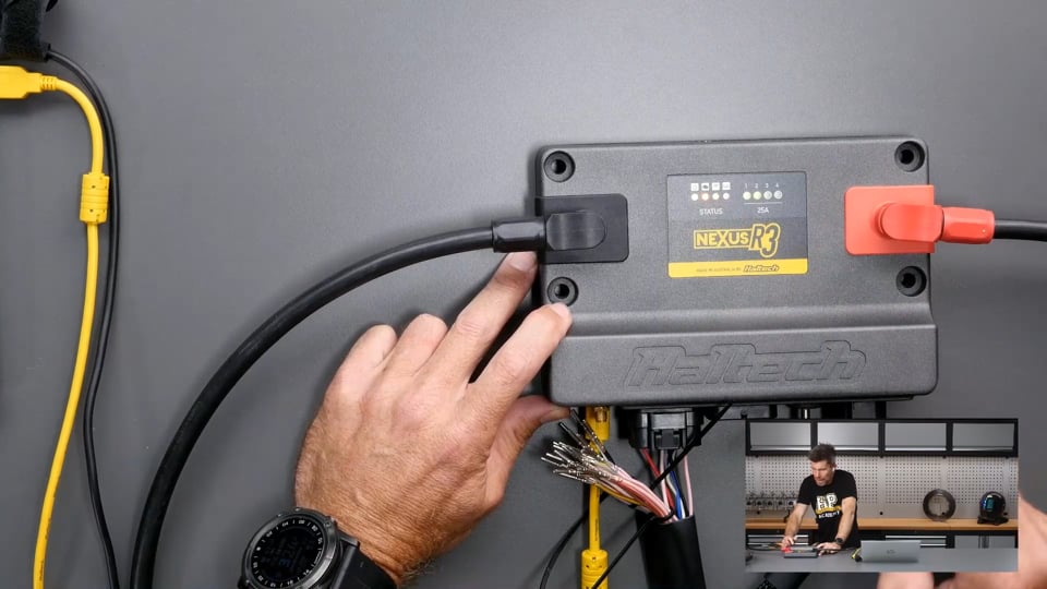
| 00:33 | Excuse our wiring mess here, obviously we've got a bit of a bench harness going on here just so I can demo one simple thing but this is the R3, little brother to the R5 that's been out on the market now for I guess probably 18 months or thereabouts. |
| 00:48 | Unique in so much as at least to the best of my knowledge right now, it is still the only ECU that's incorporating a full engine control unit and power distribution module inside of the one unit. |
| 01:00 | Now the R3 is a little bit stripped down from the R5, specifically it's got four dedicated 25 amp outputs and again if we jump to our overhead here, we've actually got LED indicators here for those 25 amp outputs, we've got some status indicators over here as well and a little hard to see but this particular connector here on the side of the unit, this is for our 25 amp outputs. |
| 01:27 | That's quite important because the rest of the connectors which we can see here, we can see some of the wiring that we've stripped out there for our bench test, these are the generic AMP superseal 1.0 connectors and the problem with those is that the maximum current you can feed through one of those terminals is somewhere around about the eight amp mark so obviously 25 is not eight so you're not going to do very well trying to get 25 amps out through an AMP superseal connector. |
| 02:00 | How a lot of power distribution modules do deal with this is that they will allow you to double up or even triple up on pins but for simplicity and given that this is a clean sheet of paper design, Haltech actually incorporated a different connector that has a larger terminal in it that is capable of supporting the heat generated with a 25 amp draw and that's why again if we go to our overhead you can see a little tricky, but you can see the gauge of wire is pretty serious for those 25 amp outputs so we've got the four 25 amp outputs, these are also capable of pulse width modulating which in the world of power distribution modules is still not the norm which is a little weird I think. |
| 02:48 | Most power distribution modules still just switch these on and off. |
| 02:54 | If you're not sure or aware of what pulse width modulation means, what we're doing is pulsing the output on and off. |
| 03:01 | You could think of it like a dimmer for your light switch. |
| 03:04 | So instead of just having your light either fully on 100% brightness or completely off, you can move it anywhere in between and we'll actually see that in action so that's quite nice for the control of the likes of the thermofan which is what we're going to be demoing. |
| 03:19 | But you could use this for fuel pumps or basically whatever you want to speed control. |
| 03:24 | So in terms of that R3, it is really designed here not as a full vehicle electronic control platform. |
| 03:35 | Obviously it is relatively limited, you've got the four 25 amp outputs, I haven't mentioned that it's also got six half bridge outputs as well which are rated at eight amp, those come out through the AMP superseal connectors. |
| 03:47 | So the half bridge outputs, we would typically be using these for drive by wire. |
| 03:51 | For a drive by wire application, the half bridge outputs, we need two of them so anything that's spare can then be used as essentially a PDM output, so you can power whatever you want off those. |
| 04:04 | But basically it's set up so that it has enough power distribution module functionality to be able to control the engine and all of the engine accessories. |
| 04:15 | Such as thermofans, fuel pumps etc, with relative ease. |
| 04:21 | You can also incorporate CAN based keypads, been having a little trouble with that which I'll talk about in a bit more detail as we go, to control these functions or you can control them automatically, there's a lot of flexibility in there. |
| 04:34 | So let's just take a quick step back as well, for those who maybe are not aware of what a power distribution module is, nothing particularly new here but these have been around in professional motorsports for decades and they were horrendously expensive. |
| 04:52 | Over the years we've seen a lot of aftermarket companies, aftermarket electronics companies come into this market and produce units that have come down in price to the point where they're a bit more accessible and they are now affordable to the point where we're seeing them used more and more in grassroots builds, street cars and club level racecars so it's no longer just used for professional level motorsport. |
| 05:18 | So essentially the power distribution module, instead of using a conventional relay to switch the power supply to a circuit, let's say our thermofan because it's going to be our demonstration here today, we're also conventionally also going to need to mechanically fuse that particular circuit so if the thermofan fails or shorts to ground or there's a wiring issue, maybe one of the wires gets cut though and shorts to ground, we need to protect that circuit so that we don't go overcurrent and end up causing a fire or something of that nature so that has conventionally been done with a normal fuse. |
| 05:57 | Problem with those fuses is that while they work, they will protect the circuit, once the fuse blows, that's it, you can't really fix that circuit and reintroduce voltage, current flow to it without actually replacing the fuse. |
| 06:12 | Now that might not be so much of an issue if you've actually genuinely got a problem in your road car, going to be sidelined on the side of the road which is frustrating but it's definitely not the end of the world. |
| 06:23 | However in a race application, this could end up being a real problem for you so with power distribution modules we get a little bit smarter and instead of mechanically switching the circuit using a relay, this is done using solid state electronics which is all housed inside the ECU in this case or power distribution module. |
| 06:46 | It is then electronically fused and the benefit of this is that we can set the fusing point, or current that it's going to electronically blow that circuit at and then we can also make it retry. |
| 07:00 | So this is great if you've got something that is just on the brink of failing and it's pulling a little bit more current than it should, we can basically retry that circuit and it might just be enough to allow us to creep that vehicle back to the pit. |
| 07:14 | So that's the idea here, standalone PDMs or built in like the R3 and R5, really no different. |
| 07:20 | And while again we are demoing here on the R3, the Haltech PD16 which is an add on unit which we can also use with the Elite, the process of using one of those is really no different. |
| 07:35 | So that's a bit of a background on what these are. |
| 07:38 | I will mention here, as usual, we will have questions and answers at the end of the webinar, this will probably be a slightly shorter webinar as well because it is a relatively straightforward topic so if you do have questions, I'll put a shoutout for them but I'd suggest you get in reasonably quickly. |
| 07:56 | Alright so let's head across to our laptop software here, so this is the NSP software. |
| 08:02 | This is for programming and controlling the Haltech Nexus range of ECUs, plus the R3 and R5 and you can also update your existing Elite to run on the Nexus platform, the NSP platform I should say. |
| 08:20 | Probably for existing Haltech users who haven't made that switch, there is absolutely no reason not to, it's a great piece of software, really nice to use in comparison to the existing ESP software. |
| 08:33 | The biggest benefit you're going to find off the bat, and it might seem like a slightly irrelevant one but I assure you it isn't, it's the time that it takes for this to connect to your ECU is lightning fast, that was one of my real pet peeves with the older Elite ESP software. |
| 08:52 | It is absolutely frustrating when it takes so long to connect so that fixes what was one of the biggest gripes so let's go through things here. |
| 09:02 | This will not be a lesson on how to navigate and use the NSP software, we'll do another webinar on that once we've got a vehicle up and running with the NSP. |
| 09:12 | So let's just close everything down here, we've got our menu structure out here on the left, let me just get my little pointer up and running so that I can, there we go, I can point things out. |
| 09:30 | So our menu structure over here on the left hand side of the screen, that's going to allow you to navigate to everything that you want to control. |
| 09:38 | So we can expand that out and basically we've got everything in our little menu structure here, what we can also do in this little search box here, if you're not 100% sure where you're going to find a particular function, you can just type that in. |
| 09:53 | So what I'll do for a start is just show you what I've done here because obviously we don't have this in a vehicle, I haven't got it connected to a simulator which would be ideal and what we want to do here is be able to manipulate our coolant temperature. |
| 10:06 | You can see that's sitting at 80°, in order to do that, if we come down to our sensors here, and open that up, we've got our coolant temperature here and if we click on coolant temperature, we can see here, this is the calibration for our non existant coolant temperature sensor. |
| 10:26 | What I've got here is just the ability to set that to whatever I want. |
| 10:29 | So this is how I'm going to be basically manipulating this, change that all to 50° and you can see our coolant temperature updates while we're doing that. |
| 10:38 | Now we did also have a bit of an issue with this, one of the last times I went to actually run this, we struck a problem just before we were about to go live, there's a non documented safety limit here for the coolant temperature sensor which defaults to a certain value if you're above 4.9 volts I think, or below 0.01 or something like that so obviously we were open circuit so that's just something to keep in mind there as well. |
| 11:11 | Right so we've got our coolant temperature set up to 50°, just for the time being, we'll come back to that in a moment but if we close that down and we come down to electrical. |
| 11:21 | So this is where we're going to basically have access to everything we need for our electrical system for our PDM. |
| 11:29 | And sorry where are we going here, vehicle functions, no, just managed to get myself, engine functions, that's what I'm looking for. |
| 11:39 | Right, engine functions, we want to set up a thermofan which we'll find here in our menu structure. |
| 11:47 | So if we come down to our thermofan, first of all we want to assign the wiring, basically an output for it and this is really as easy as it is with our power distribution module side of things, it's no different from the Nexus R3 perspective, setting up a PDM output which is internally switched compared to an existing switched output. |
| 12:13 | So let's just clarify what I mean by that, a conventional existing switched output. |
| 12:18 | So with every other ECU on the market except for the R3 and R5, if you want to set up your thermofan, what you're going to do is have a switched output set up and what that's going to do is switch to ground when the ECU triggers the fan to operate. |
| 12:36 | Problem with that is that the output will only be able to handle very very low current. |
| 12:44 | I don't know for the R3 what that specific current limit is but might be in the order of maybe 200 mA, maybe 500 mA so absolutely not sufficient to support the operation of a fan, thermofans could easily draw 8-12 amps depending on the specifics of the fan. |
| 13:05 | So if you tried to run the fan directly off the ECU output or for that matter a fuel pump or anything else, when it switches on, you're going to instantly melt the transistor inside of the ECU and fry it and that's dead so that's why we need to incorporate with a conventional ECU wiring, the relay and the fuse that I mentioned earlier. |
| 13:26 | You can think of that relay just like an external switch that is electromagnetically controlled by the ECU and that then switches, it uses low current from the ECU to switch the high current side of the circuit that then feeds power to the fan so hopefully everyone can understand that. |
| 13:44 | So anyway, let's get back into this here. |
| 13:47 | So we've got the wiring here, nice thing with the Haltech software, and this is not new, this has been the way they've done it for a while and if you are using one of their flying lead looms, they're all colour coded so you can see there that the pin that we've chosen which is the 25 amp, output number four, that is red and green and that is exactly the colour that is going to our fan. |
| 14:16 | So really easy to get a bit of a visual indication on that, we can click assign and this will allow us to go through and have a look at the available outputs. |
| 14:27 | So we've got our digital pulsed outputs on the ECU so these are our conventional outputs which I was mentioning. |
| 14:34 | We've also got our half bridge outputs, these as I mentioned can support up to eight amps so not realistically going to be sufficient for the majority of fans or for that matter probably the majority of fuel pumps but plenty of circuits on the engine will be drawing less than eight amps so we can also use the PDM side of the R3 for controlling the power supply to our injectors, our coils, all of that's relatively low current draw, also power supply to things like wastegate, boost control solenoids etc so pretty flexible there. |
| 15:13 | And if we scroll down we've got our high current outputs here and I'm obviously not going to change that, we've got it set up on our output number four as I already mentioned so we can click cancel and we'll leave that. |
| 15:27 | So we've also got the active state, so when it's going to be active. |
| 15:32 | If you're wondering about any of this, you can also click on the little blue question mark and that will give you a little bit more information. |
| 15:40 | Drive type, whether it's going to switch high or low, particularly for the half bridge outputs, these can switch to 12 volts or switch to ground. |
| 15:48 | We've got the fusing current here. |
| 15:51 | So this is important here to just keep in mind. |
| 15:54 | We want to choose a current that is going to be realistic to protect that circuit. |
| 15:59 | I've got this set to 25 amps, obviously, at the moment which is the maximum. |
| 16:04 | Generally I would be setting this a reasonable margin above what the normal operating current is, nice function with this is that when it is operational you can monitor up here what the actual current draw is, you'll be able to datalog this as well so you can see exactly what's going on. |
| 16:23 | Another aspect here is our soft start current. |
| 16:27 | So what we need to understand is with an inductive load like our fan motor is that if we monitor the current, log the current in real time, as we switch it on, when we first switch it on from stationary, what we're going to see is a very large, very brief current draw which is called in rush current and that's only going to be there for maybe two to 500 milliseconds, maybe up to half a second essentially and then once the fan actually gets up to speed, we'll see that current quickly drop away to its normal operating current. |
| 17:02 | So what we can do is set a soft start current, so basically a current limit for that soft start and then we can set an operating current. |
| 17:11 | We can also set a duration for when we'll be able to use that soft start limit as well so again that might be 200 or 300 milliseconds, something of that magnitude. |
| 17:23 | So just gives you a little bit more precise control rather than setting an overall limiting, current limiting value that will allow that in rush current which is going to be much higher than the operating current. |
| 17:35 | Let's say normally the current is 10 amps, it's quite possible that it might draw 30 or more amps, 40 amps very briefly so we'd need to basically set a current limit that will allow for that in rush current which is then going to be much much higher than it actually needs to be for operation so it doesn't give us that safety so this gives us a little bit more control so we can precisely manage that and make sure that it's only going to actually fuse when it needs to. |
| 18:06 | Now we get into the other elements of a conventional power distribution module, we've got our maximum retries and we've got our retry delay. |
| 18:16 | So this is when the current exceeds the limit, what's going to happen is that when that occurs the Haltech Nexus will switch the current flow off to the device and it's going to then wait the retry delay, in this case two seconds and then it's going to try again so that retry delay is going to allow everything to cool down a little bit, it'll switch the supply back on, it'll try again and basically it's going to try in this case up to 10 times. |
| 18:47 | So by carefully selecting your retry limit, maximum retries I should say and your retry delay, this is going to allow you the flexibility with a racecar to hopefully creep it back to the pits if something is just starting to fail. |
| 19:03 | Obviously if it's a dead short in the fan, it is what it is, it will retry, it's not going to damage anything but of course the fan's still not going to operate so you're not going to get any cooling but you know there's levels to this and a lot of times, particularly if you've got a fuel pump that's just on its last legs, you'll start to see the current, if you're looking at it historically, which is another element that's worth considering here, if you're looking at the current historically, what you're going to see is over time it's going to start creeping up and you might just start banging into that current limit and obviously if your fuel pump fails out on track and pops a conventional fuse, that's your day done, you're going to have to get back to the pits and physically change that fuse. |
| 19:47 | Car's probably not going to run too well if your fuel pump is switching on and off, fuel pressure's obviously going to not be where you'd like it to be but again, might just be enough to get you back home. |
| 19:59 | Right now another element that's worth just covering off here is the fan one mode, so how we are going to actually operate this fan and at this stage you can see I've set this up to digital and duty cycle. |
| 20:15 | We'll have a look at that first, click the wrong button there, we can set this up as duty cycle or switched output. |
| 20:21 | Switched output would be how a more conventional fan output would be switched. |
| 20:26 | We can also have a CAN output switched as well but we're not going to be dealing with that so let's leave it on duty cycle at the moment. |
| 20:33 | So this is our basic setup here. |
| 20:37 | When we've got that duty cycle mode enabled, what that gives us is over on the left hand side it gives us our duty cycle table option, that won't be there if are looking at a conventional switched output but let's have a look at our duty cycle table and we've got that set up there with axis break points every 2° from 90 through to 100 and we've got our duty cycle that we can set up so at the moment again we've got our temperature set to 50°. |
| 21:09 | This from memory though will apply this below 90 so what we can do is just try this, I think this works, I'll bring our fan into shot here and let's just start with a relatively low duty cycle, we'll set it all to 10 and our fan is going. |
| 21:30 | So we can step this up obviously. |
| 21:35 | And we'll go all the way to 100%. |
| 21:42 | Quite nice doing it like that because when we do it switched which I'll do in a second, when it goes from 0 to basically 100% duty cycle instantly it's actually quite a torque reaction so I'm going to have to hold onto that a little bit tighter. |
| 21:54 | The duty cycle control is actually a really nice way of doing this and given that it's got this option, I really don't see why you would want to switch it. |
| 22:04 | What it gives us is a little bit more granularity around the control so what we might want to do here is start at maybe 90° with 20%, obviously that's going to run there. |
| 22:17 | Turn it off so it's a little bit quieter. |
| 22:19 | Then maybe when we get up to 92°, maybe we want to step it up a little bit higher, go to 40, then 80 and then maybe from 96° and above, we might want to set that up to 100. |
| 22:30 | Basically what you want to do is set this so that you've got good control. |
| 22:34 | Using the duty cycle control like this, you don't tend to get that in rush current because it's not trying to go from 0-100% in an instant like that so it's a little bit quieter, there's less electrical load change on the vehicle and all around it's just nicer which is why we see that this is generally the technique that most OE vehicles are using. |
| 22:57 | So that's our first option there. |
| 22:59 | If we come up to our digital fan, we can also set up the frequency that that pulse width modulation is occurring at, 250 Hz there which seems to be a pretty good place to have that set up. |
| 23:13 | We've got the trigger source here which, coolant temperature sensor obviously makes sense. |
| 23:18 | We've got the ability here to also disable the fan when the engine is stopped if you want to. |
| 23:25 | Obviously going to stop that fan running, potentially running down your battery voltage if you've got the vehicle at a hot operating temperature and you've got the engine shut off but the ignition on, something that can be quite handy, I see this a lot when I'm downloading datalogs or making programming changes to an ECU at a race meeting, car will come back in from a session out on the track, everything's hot, we shut down the engine and particularly with little batteries it doesn't take a lot of fan operation for the battery voltage to start dropping down. |
| 24:00 | It's also not particularly effective because unless you've got an electric water pump, when you've got the engine shut off, you're actually not doing much to cool the water that's flowing through the engine past the coolant temperature sensor, essentially the fan's only got the ability to cool the water that's sitting in the radiator so it actually won't shut off very quickly either. |
| 24:21 | Now the other option we've got here is an override switch enable and of course, when I tested this prior to this webinar, everything worked absolutely flawlessly and today, it hasn't but I can still talk through how this works. |
| 24:37 | So essentially you've got the option, you can do this however you want but how I wanted to demonstrate this, which is now not going to work is with one of Haltech's Gray Hill CAN based switchpads. |
| 24:48 | So obviously we can use these for a variety of other functions on the vehicle anyway and this is again becoming a lot more common to incorporate a CAN switchpad into cars with the current crop of ECUs, particularly with PDMs for function control. |
| 25:05 | So what you have to do for a start is make sure that under the CAN connections down here, under the Haltech CAN system we actually have the CAN switchpad enabled. |
| 25:19 | And then we do have this not connected which obviously it isn't connected but again prior to this, I was having a little trouble with it so I'm just going to talk through it. |
| 25:29 | So once you've got that keypad up and running, set up, wired up to the CAN bus, nice thing with this is it is only four wires, 12 volts ground, CAN high and CAN low. |
| 25:39 | If we come up to our fuel pump, sorry thermofan and click the override switch here, this will flash this little weird warning up here, this little red icon I should say, just telling us that we do need to reboot which is fine, we can click that and that will happen. |
| 25:58 | So it will give us the override duty cycle probably you're going to want to run the fan at 100% if you are going to use this override. |
| 26:08 | Then what you see is that the little wiring option menu on the left hand side is now turned red. |
| 26:15 | Bringing our attention to the fact that this needs something done so we'll click on that. |
| 26:20 | And we now get this thermofan override input option that wasn't there before and that warning is telling us that this is not assigned. |
| 26:29 | So what we can do is click assign. |
| 26:32 | So we can assign this to a switch input but if we scroll back to the bottom we can see that we can now assign this to any of the keys on our keypad. |
| 26:44 | So we'll assign it to our top left key and our job is done, oh we've also got how that mode will work, so whether it's momentary which would probably be a little bit useless, basically momentary, the fan will run when we're touching the button, so if we come down here, so we would probably want to have that latching, essentially push on and push off. |
| 27:07 | Alright so that should set up our override but as I mentioned, today not so much but the principles will remain even if I can't demonstrate that particular functionality. |
| 27:18 | That also does again require a reboot. |
| 27:22 | OK let's show the other option here which we want to come back up to our fan one mode, I'll just check my temperature is OK here and what we'll do now is change from duty cycle to our digital switched output. |
| 27:38 | Again tells us that we need to reboot so we'll go ahead and do that. |
| 27:46 | Now what we need to do, if we go back to our thermofan, we've got a few other options here that are now relevant so we can see we've got our enable above and disable below. |
| 27:58 | So this is important to make sure we've got a little bit of a difference here in our switch on and switch off temperatures which is called hysteresis just to make sure that if our coolant temperature is sitting at the switch on point, the fan's not going to be constantly cycling on. |
| 28:13 | So what this means is that in this setup here, it's going to switch on above 88°C and then the coolant temperature will need to drop down below 86 before the fan switches off. |
| 28:26 | So that's how that is going to work. |
| 28:29 | So let's have a look at that. |
| 28:32 | And we want to basically come up to our sensors here, come up to our coolant temperature, I'm just going to have to hold onto this fan so it doesn't take off on me because it does create a bit of torque as I mentioned, just make sure I've got that but do not have my fingers in the way, that could end badly. |
| 28:50 | Let's set all of that to 90°, oh 90° and our fan should now switch on. |
| 28:59 | There we go. |
| 29:02 | And we can see that our coolant temperature is now showing 90°. |
| 29:08 | Let me just, while I'm doing this, you can see here we've got some channels set up here which is showing all of the relevant information for that output, high current output for. |
| 29:25 | You can see at the moment that that is pulling five amps. |
| 29:29 | So let's just set that back to 50° and it will switch off. |
| 29:34 | So just, I should have mentioned that before, what I will do I think is just for completeness, let's go back to our thermofan wiring here and we'll set this back up to our nice little duty cycle control 'cause it's a little bit easier to use. |
| 29:53 | Let's get our duty cycle here set to something like 30% so it's not going to be too loud, not going to be too obnoxious. |
| 30:06 | And now if we come up to our coolant temperature... |
| 30:13 | No I have not got that information now but that's OK, if we come down to our wiring here, we can see that if we look here, 250 Hz, so we know that it's being pulse width modulated, 30% so we know that's the duty cycle it's being pulsed at, it says it's pulsing and we can see the voltage cycling there but that's not really too relevant, it's showing us the current load sitting at 7% and the current, peak current there at 8.5 amps so we've got the ability to basically monitor everything that is going on. |
| 30:48 | Let's come back to our duty cycle and we will switch that off. |
| 30:53 | Right as I mentioned, it is a relatively straightforward procedure there. |
| 30:57 | Wasn't going to take too long to demonstrate this, I will get into questions in a moment so this is a good time to just mention if you do have any questions, please ask them now. |
| 31:08 | But essentially the ability to set the PDM outputs up on this really looks no different to an existing digital pulsed output, the process is exactly the same there but we do have the benefit of being able to set the duty cycle control there for our fan as mentioned also you could do this for something, basically any of the outputs that you want to speed control and then you can also monitor the current, the voltage at that output, you can datalog all of this as well and again that's really quite useful if you want to get that historic data over time of how a component like a fuel pump or thermofan is operating and start taking note, maybe be a little bit proactive if you start to see that the current draw is slowly creeping up event after event, that can be an indication that something is not right, maybe your fuel pump is on its last legs and about to die or maybe you've got a blocked fuel filter or something of that nature and the pump is working harder than it normally should. |
| 32:17 | Right I'll head across and just see if we do have any questions. |
| 32:23 | And it doesn't look like we do. |
| 32:26 | Hopefully that means that I've done a stellar job of explaining this and it's absolutely crystal clear to everyone. |
| 32:33 | Oh no we've got one here from Jason who's asked, can a PDM output, current, voltage etc be diagnosed with the software oscilloscope? Yes it can, you can monitor the current with, or the voltage for that matter, with the built in oscilloscope in the NSP software so that's another way you can monitor that. |
| 32:55 | Either the scope or datalog it and view the datalog file. |
| 33:02 | Nothing else so we will leave it there. |
| 33:04 | As usual, if you are viewing this at a later point in our webinar archive, feel free to ask any questions you may have in the forum and I'll be happy to answer them there. |
| 33:13 | Thanks for watching and we'll see you next time. |
Timestamps
0:00 - Physical overview
4:34 - What is a PDM
7:56 - NSP vs ESP software
9:12 - Menu structure
9:53 - Thermofan setup | Assign output
15:27 - Thermofan setup | Active state
15:40 - Thermofan setup | Drive type
15:48 - Thermofan setup | Fusing current
16:23 - Thermofan setup | Soft start current
18:06 - Thermofan setup | Maximum retries
19:59 - Thermofan setup | Duty cycle control method
22:59 - Thermofan setup | Operation settings
24:21 - Thermofan setup | Override switch enable
27:22 - Thermofan setup | Digital switched control method
30:53 - Summary
32:17 - Questions


