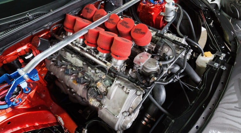
It's not very often that you will come across an engine with 6 individual throttle bodies and a turbocharger. A lot of tuners won’t even experience this and if you aren’t aware of how to handle it, it will be practically impossible to achieve an accurate tune that will give you good fuel and ignition timing control as you vary throttle position and boost pressure. In this article, you will learn the steps required to achieve an accurate tune with a turbocharged individual throttle bodied engine.
In this article: The Issue With MAP Tuning | Using Load Axis of Throttle Position/Alpha-N Instead | Injection Time-Based Fuel Model Solution | Volumetric Efficiency Fuel Model Solution | Using 4D Fuel Compensation Tables| Conclusion

The Issue With MAP Tuning
The problem with individual throttle bodies, regardless of whether your engine is turbocharged or not, is that when they are fitted and the large common plenum chamber and single throttle body are removed, manifold air pressure can no longer be used to indicate engine load. Instead, you will be using the speed density tuning principle whereby you calculate mass airflow using manifold absolute pressure and the ideal gas law instead of measuring it directly, but why is this the case?

A naturally aspirated engine with individual throttle bodies has a very short runner length post throttle body as there is no large common plenum like that of a single throttle body engine. Because of this, the manifold pressure after the throttle bodies may reach atmospheric pressure from as little as 30% throttle so if the MAP signal is used as your load axis, once 30% throttle opening is reached you are operating in the top row of your fuel table and will stay there as you move from 30% to wide open throttle, giving you abysmal control of the fuel delivery. If you have the air/fuel ratio correct when you first get into that row, by the time you get to wide open throttle the airflow will have dramatically increased and you will be running extremely lean. On the other hand, if you tune the engine so that the air/fuel ratio is spot on for wide open throttle conditions, when you back off the throttle you will be running extremely rich. A turbocharged engine will give the same results only magnified.

Using A Load Axis of Throttle Position/Alpha-N Instead of MAP
In order to get good control fuel and ignition timing control, you will need to use throttle position, also known as Alpha-N, as your load axis instead of manifold air pressure. When using throttle position, it is important to consider the resolution since airflow through the throttle body is non-linear. When you first open the throttle body, you will get a large increase in airflow but the further you open it, the less it increases. It is therefore important to have small breakpoints around the closed throttle area.
If you are running a naturally aspirated engine, using throttle position as your load axis is the end of the story however if you have a turbocharged engine, there is a lot more to it since your airflow can vary dependant on manifold pressure as well as your throttle position. This means you need to be able to vary your fuel delivery based on both parameters which on face value seems difficult as you are now looking at a 4Dl fuel table with fuel versus throttle position, RPM and manifold pressure. To further complicate matters, you might also want to change your target air/fuel ratio as your boost pressure changes
Whenever you are tuning an individual throttle body turbocharged engine, you need to consider the fuel equation that the ECU will use. For example, with a Link ECU, this is described as equation load source which for most engines will be set to Load=MAP meaning that if the manifold pressure is doubled, the ECU will double the fuel supply which should maintain a consistent air/fuel ratio. Other ECUs will have a 1:1 absolute pressure compensation table to achieve the same result.

Injection Time-Based Fuel Model Solution
There are three solutions to the issues caused by tuning with turbo and individual throttle bodies that we will discuss here. There is no right or wrong way of doing this, it comes down to the ECU you are tuning and your personal preference.
The first solution is using an injection time based fuel model. Running in this mode, coupled with having an open loop lambda table, makes this operate more or less the same as a volumetric efficiency based fuel model. The only difference being that you don’t take into account engine size or injector flow characteristics which means the numbers in your fuel table don’t represent accurate volumetric efficiency numbers.

As with a lot of injection time based ECUs, in the Link ECU we are using, you have a master fuel number that is currently set to four milliseconds which means that if you have a number in the main fuel table of 100% and you’re running at 100kPa, before any background compensations are applied, the injectors will be open for four milliseconds.

To see how this works and enables you to maintain your air/fuel ratio as manifold pressure changes, let’s look at the air/fuel ratio lambda target table. The important thing to note here with this overlay table is that the load axis is now set to manifold pressure, as opposed to your main fuel table that is working with throttle position. This gives you the ability to change the target air/fuel ratio based on manifold pressure, so it is important to set realistic targets. In the above table, for example, a large area is set to a target of lambda one as this is a street engine that will spend a lot of time cruising, so good fuel economy is desirable.
In case you were wondering, the ignition table is just set up with the conventional manifold absolute pressure axis. It is the fuelling that is the difficult part with an individual throttle body engine.

Next, you can make tuning changes which involves exactly the same process as tuning any speed density system, you can simply make adjustments to the numbers in your fuel table until you are on target. It is very easy for you to accurately access each of the zones since you are only dealing with throttle position, not manifold pressure which is just automatically happening in the background due to the calculation you have set up.
Just like with a volumetric efficiency based fuel system, if you make a change to your air/fuel ratio target in your air/fuel ratio table, it will affect your injector pulse width which means your fuelling will change. This is due to the open loop lambda table setting that we discussed earlier, being set to “on”, which applies a correction factor in one adjustment so that if your air/fuel ratio is too rich or lean, this is corrected.

Next, let’s have a look at a couple of runs on the dyno. Above you can see we have air/fuel ratio at the top in lambda with a target of 0.82, manifold absolute pressure and then power at the bottom. For our first run (shown in purple), we ran on wastegate spring pressure, around 10 psi and as you can see above, the air/fuel ratio tracked just above the white reference line which is exactly what we want to see. The ECU is doing its job even though we are only running in one row of our throttle position fuel map. As you can see from the second run in red, where we extended the wastegate duty cycle table out into the areas we were running in and targeted 220 kPa, apart from a lean hole at the start of the run, we were on target, however, there is a little more to it than that.

The issue we have is that at the top end, the air/fuel ratio is drifting slightly rich but this effect isn’t too dramatic because we were only running at 220 kPa. If you want to correct that rich area, you have to go to your fuel table and remove a bit of fuel in the areas that were rich but this presents a problem as this will also lean out the air/fuel ratio when you are at your low boost setting. You cannot resolve your high boost problem without affecting your low boost. What you will see is from you minimum wastegate pressure up to about 15 psi of boost, everything will track nicely but as you increase the boost pressure and the turbocharger starts to restrict the exhaust flow, the air/fuel ratio will taper off richer. We obviously need a way of dealing with this situation.

To deal with the air/fuel ratio tapering off richer you can add another compensation table, in this case, we will use the 4D fuel table which was previously set up. This has a load axis of manifold pressure and provides a percentage change to our main fuel delivery, in this case at high RPM and boost, it is set up to remove a bit of fuel.

Volumetric Efficiency (VE) Fuel Model Solution
In more modern ECUs, you can achieve the same as we just looked at by using the volumetric efficiency fuel model. As we alluded to earlier, the ECU will require more information when using this model such as injector size, fuel density and stoichiometric air/fuel ratio. In a volumetric efficiency based fuel model, the air/fuel ratio target table acts to adjust the fuel delivery. The setup, however, is the same as with the traditional model in that the volumetric efficiency table is set up based on throttle position and the air/fuel ratio table is based on manifold absolute pressure. You will also still need to use the 4D fuel compensation table to correct the air/fuel ratio at high boost, high RPM. Really the only difference is that the numbers you enter into fuel table should be representative of true volumetric efficiency.

Using 4D Fuel Compensation Tables
The last solution we will look at is one you can use if you don’t have an open loop air/fuel ratio target table. This starts off exactly the same in that the main fuel table is tuned relative to throttle position but there are a couple of things to check in your fuel main settings. You still need to make sure that your equation load source is set to Load=MAP but this time we will need to disable your open loop lambda target table which means the air/fuel ratio target table will have no impact whatsoever on your tuning, meaning you will be tuning solely via throttle position. As we have discussed, the problem that comes with this is that you will have no way of adjusting fuel delivery as the manifold pressure changes. You could have 100% throttle at 100 and 150kPa but you obviously want different air/fuel ratios.

This is where the 4D fuel compensation table comes in again in order to make a percentage change to the fuel delivery, it basically does the same as an open loop air/fuel ratio table would. To calculate the correction, you need to use the correction equation which is measured air/fuel ratio divided by your target air/fuel ratio. In this case, we are assuming that you have tuned to lambda one and your target air/fuel ratio at 220 kPa is 0.80 so you would divide 1 by 0.8 which gives you a figure of 1.25. This means that you need to add a correction factor of 25% to that row in your 4D fuel table and then continue on for each point. You will also need to correct the same issue we discussed previously at high boost pressure where your turbo becomes restrictive.

Conclusion
As you can see, this is quite a complex topic and that, combined with the fact that a lot of tuners won’t ever come across this type of engine makes it unsurprising that few people know how to deal with it. Hopefully, you can see that if you maintain a methodical, precise approach, you can achieve an accurate tune with your turbocharged, individual throttle-bodied engine and this is a topic covered here at HPA in detail both in the EFI tuning course material and members-only webinar lessons.