Sale ends todayGet 30% off any course (excluding packages)
Ends in --- --- ---
Just wanting to clarify my CAN network wiring.
In the example on the course all the wires are crimped into 1, a star pattern if you like. Easy way to do it, but not entirely suitable to go across a dashboard.
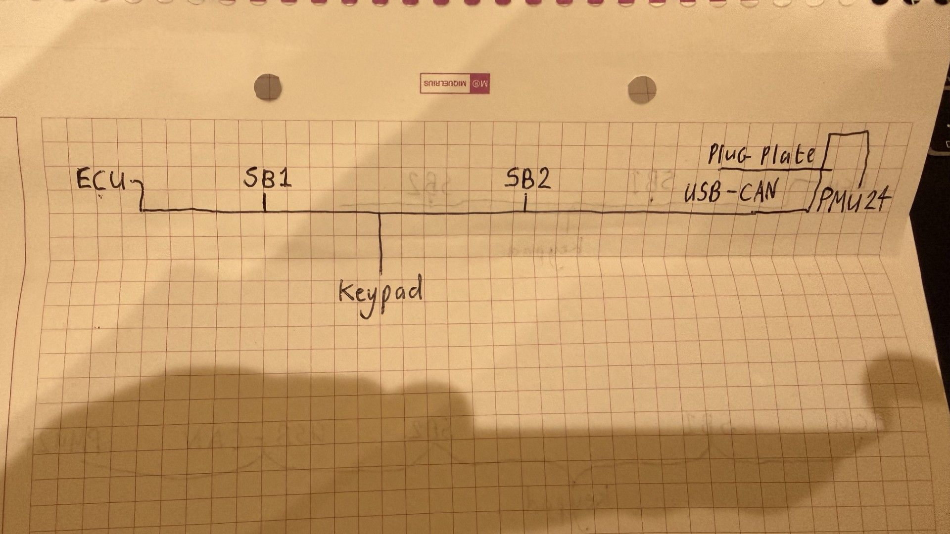
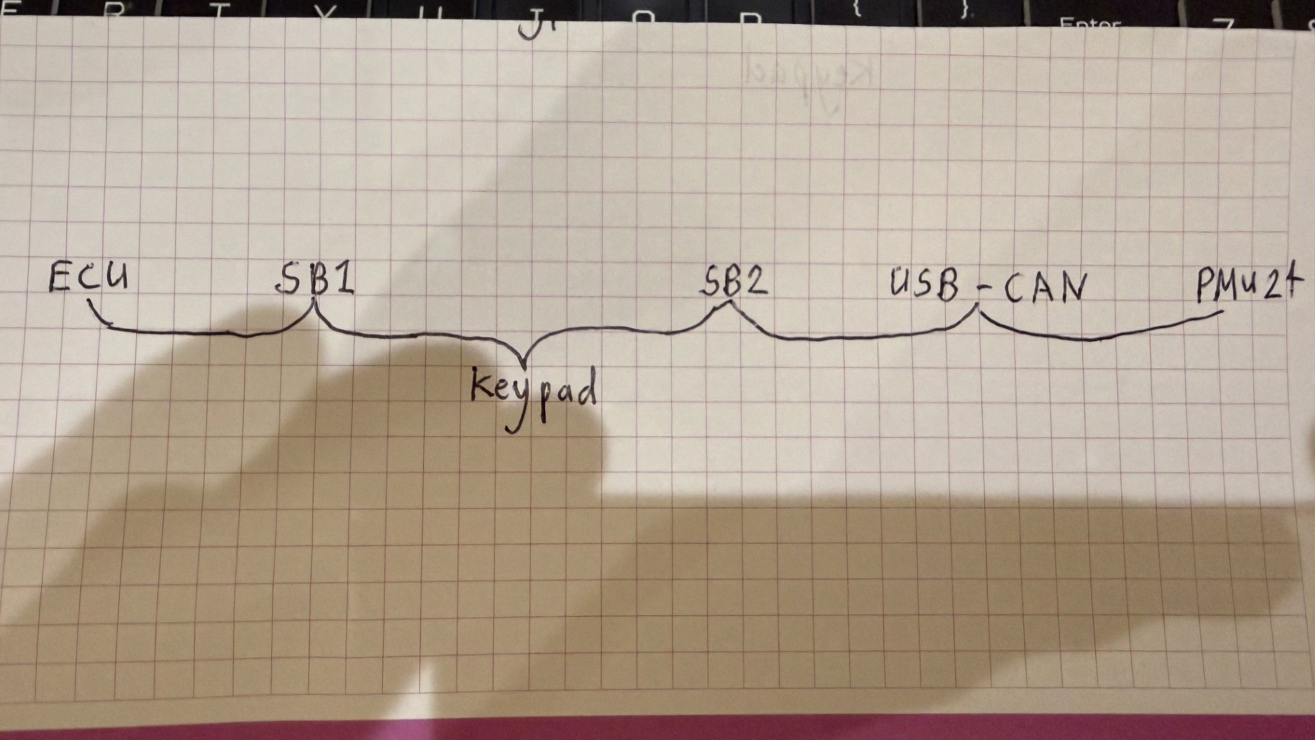
I plan to run mine from left to right. ECU > Switchboard 1 > Keypad > Switchboard 2 > USB-CAN > PMU24. They are mounted in that order under the dashboard. ECU has resistor, its not switchable, so makes sense to have that first. PMU24 has a switchable resistor so that works well at the other end.
Is it better to have effectively 1 wire running the whole way across with all the wires from the devices spliced into it at right angles or is it better to have them wired in more of a daisy chain fashion, spliced into each other at the connector pin? I have a feeling both ways would function, but some clarification would be useful.
If I choose to splice them into a main wire, is it better to cut the main wires at each open barrel splice and effectively crimp the continuing wires together or is ok to try and strip just enough sheathing to allow the joining wire to be spliced into the main wire without cutting it at each adjoining wire?
Spliced from the side:
.
.
Daisy Chain
I have also considered using a 6 port CAN hub, this would be easy, but would add extra wires that could be avoided. I may still add a small hub, to allow easy future installations. Otherwise I guess I just leave a free floating DTM plug somewhere close to the SB2 input where I can easily plug additional devices into. Its quite likely I will also add in a CANChecked CAN gauge, so perhaps best to leave 2 blank empty plugs.
Thanks for any advice.
Hey Ian,
It’s best to think of the CAN network as a single main trunk. It starts at one terminating resistor and ends at the other. These can either be standalone resistors or built into components, and since your ECU can’t switch its resistor on or off, you’re spot on treating that as one end.
Everything else on the network is effectively a node that branches off that main trunk. The big thing to keep in mind is branch length — ideally under about 200mm, 300mm max. That’s one of the biggest factors in keeping the network stable.
In terms of layout, both of your approaches will work. Daisy chaining through connectors is effectively just extending the trunk through each device, and I’ve seen plenty of setups like that work fine. That said, my personal preference (and what you’ll generally see in OEM-style harnessing) is to keep a clean main trunk running the length of the harness and splice branches off to each device. In practice, you’re usually branching power and ground at those same points anyway, so it makes sense to bring CAN in there as well and keep everything neat and consistent.
For the actual splice method, again both ways will work, but I prefer treating each section as its own wire and doing a proper splice rather than stripping into the side of a continuous wire. I find it easier to build, easier to manage in the harness, and you can add a bit of length or loop back slightly which helps with strain relief. It also gives you a bit more flexibility if something ever needs to be changed later. Long story short, as long as the connection is solid and protected, it’ll work, but I find the “cut and splice” method more practical.
I’ve used CAN hubs before and they definitely make things easier, especially if you’ve got a few components in a small area. The only downside is, as you said, they can add extra wiring that you might not really need, and you still need to be mindful of how long those runs are getting, since it’s effectively the same as adding multiple stubs.
Planning ahead for more CAN devices is a really good idea. Leaving a spare connector with power, ground, CAN H and CAN L somewhere accessible (like behind the dash) makes adding things later super easy. Just remember that’s still a branch, not a continuation of the trunk, so it should only feed one device.
One thing I like to do when designing a harness is have one end of the CAN trunk terminate through a connector rather than permanently in the loom. You can get Deutsch connectors with resistors built in, or just bridge it yourself. That way if you ever want to extend the network, you just unplug the resistor, keep running the trunk, and terminate it again at the new end. Makes future changes way easier.
I’ve attached that Link example as well because it’s a good visual of what’s going on.
Hope that helps a bit — happy to go into more detail if needed.

Hi Caleb
Thanks for the reply. That clears my ideas up for me.
.
I'll run a main trunk along the inside bulkhead behind the dash and splice off that for each device. The only device that could end up further away than 300mm is the keypad, but I can reduce this a lot by moving the main trunk as close as possible to that before the node for that splices in.
.
Before I go ahead with making the harness I will have decided where the gauge will go, so I can add a node in for that also. I plan to make a connector plate for the PMU, using DT/DTM panel mounts for servicing of all the inputs and outputs from the various sub harnesses. The CAN connector on this was going to feed straight into the PMU, but I could easily make the node going to the PMU be second to last and add an additional panel mount DTM4 there as the end of the CAN network and add a resistor to a DTM there.
.
.
For the splicing, I am still at the planning stage for all my chassis harnesses, but I noted that keeping a large earth wire as one piece, then stripping back a section of insulation and open barrel splicing the smaller earths into that is how the OEM chassis harnesses were done. I think I shall make my replacements in the way you suggested and treat each section as its own wire.


