Sale ends todayGet 30% off any course (excluding packages)
Ends in --- --- ---
I am hoping that some of you can help me out. I am working with the Bosch 0 261 230 093. I have attached the data sheet. I am working with a Holley EFI system which offers a great deal of flexibility with the sensor configuration.
I wired the sensor as per the data sheet:
Pin 1: sensor ground
Pin 3: 5v reference
Pin 4: signal back to the ECU
I configured it as 0.5-4.644v 0-500kPa linear as the data sheet calls for.
The issue is that I am not getting any readings on the sensor. I have another fuel pressure at the rail that shows rail pressure when the fuel pump is turned on.
I am wondering if I need to wire pin 2. I am not exactly sure what it is. My guess is that it is a fuel temperature sensor wire, but I am not certain.
Any help is greatly appreciated.
Andrew
"NTC (Negative Temperature Coefficient) thermistors are thermally sensitive semiconductor resistors which show a decrease in resistance as temperature increases."
Not something I'm familiar with, but it looks like it may be a correction/regulating circuit for temperature variations, a voltage/current stabilising circuit and/or something else.
Thanks for the reply. It makes sense that there would be a temperature correction for the fuel differential pressure. The question is how this is wired, as the PDF is not clear, or I just don't understand it. It would be really great to have this sensor figured out since what most of us are interested in IS differential fuel pressure and not just rail pressure.
Any other inputs and suggestions are welcome!
Andrew
I would verify the raw voltage the ECU is logging from that sensor input to narrow things down a bit. For example, if it's getting 0.0 Volts, then you'd want to check your 5 V supply to see if you have power on the correct pin.
I did verify that the sensor was getting 5v across pins 1 and 3, which are the sensor ground and 5v reference, respectively. I did not check the raw voltage at the sensor, but I did change the calibration so reflect a different value at .5v and it read that value, so I know it is getting at least .5v on the sensor wire.
I feel like I am missing something here with the NTC circuit...
Andrew
Many systems output the minimum calibrated value while the sensor input voltage is equal to or less than the minimum calibration voltage value. That does not confirm current input voltage. It only take a moment to actually check and that's the first step in diagnosing an issue like this.
You certainly may have a more complex issue, but let's start with the basics and go from there. If the sensor voltage isn't reaching the ECU, no sense getting into more work adding a temperature sensor unless you want temperature data. Your pressure sensor's analog voltage out may simply be wired to a different input that your software configuration is expecting, for example.
I had a chance to fiddle with this thing again. My friend Vic made a sensor holder and we addd a 1/8" NPT port to it so that we can pressurize it with regulated shop air.
Everything was wired as before. I got a consistent 4.91 volt across pins 1 and 3, which are sensor ground and 5v reference, respectively. The signal wire was on pin #4, and regardless of the pressure, it consistently had 0.49v
I then looked at the data sheet again, and noticed that perhaps the signal wire need a 680kOhm pull up resister (see PDF document in the original post). I added a 680kOhm resister from the main power fed to the ECU.
Zero change...Same 0.49v no matter the pressure that we fed it.
This shouldn't be that hard. I am open to suggestions.
Andrew
I did a little more Googling around and I found some conflicting pin-out information for the sensor. I reconnected the wires as follows:
1: Sensor signal
2: 5v reference
3: (This is the temp and it does not seem to work for now)
4: Sensor ground
With the above connections and a regulated air supply, the sensor read accurately and followed the pressure as I changed it on the air compressor regulator.
Hopefully this will be useful to anyone using this sensor.
Andrew
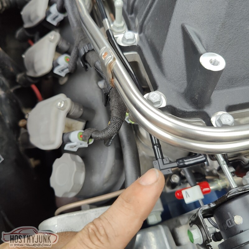
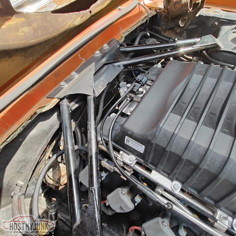
I just wanted to add a little more information in case anyone wants to use this sensor on their project. Here are a few pictures of how the sensor was connected. This sensor is being used on a LS3 engine with a LSA supercharger. The supercharger has a port that has both engine vacuum and boost. I used a small rubber elbow and a plastic fitting that is connected to a length of nylon hose.
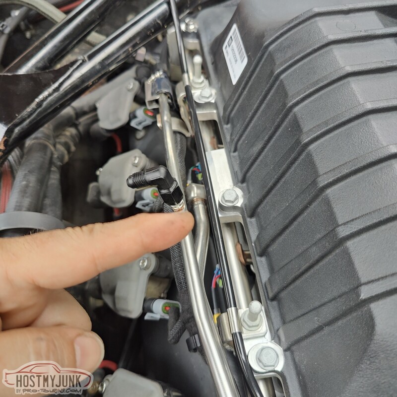
The nylon hose runs along the fuel rail and is held in place with some stainless P-clamps.
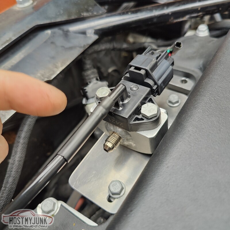
The sensor is mounted to a plate that is bolted to the back of the intercooler lid.
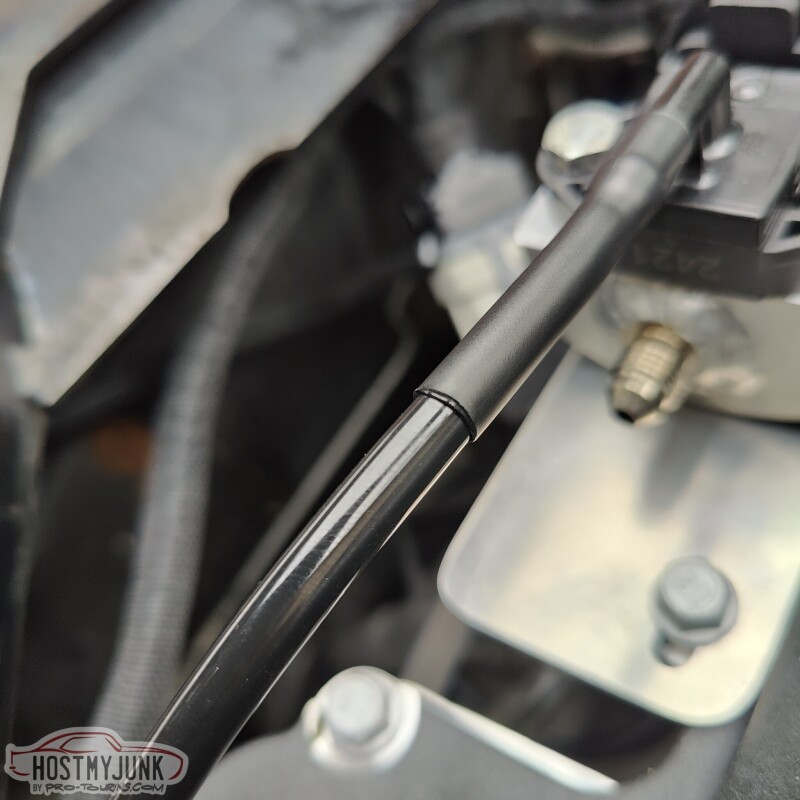
I used Raychem SCL (thanks to the wiring fundamentals course for turning me on to this stuff!) to mate the sensor nipple with the nylon tubing.
The last part was connecting a fuel supply line to the sensor. This was done using a pre-made brake hose that is 13in long and has a straight AN-4 fitting at the sensor and a 90 degree fitting at the Schrader valve.
Andrew
I'm glad you've got it sorted! Well done.