Sale ends todayGet 30% off any course (excluding packages)
Ends in --- --- ---
Discussion and questions related to the course Practical Motorsport Wiring - Club Level
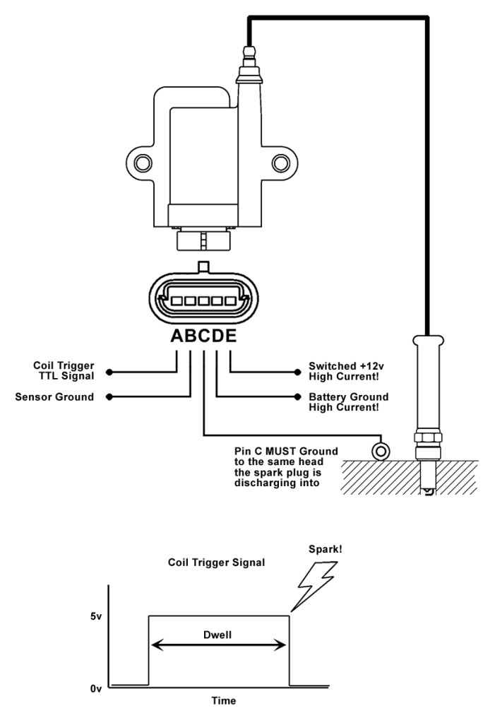
Yo, I'm building an entire engine loom from scratch for my modified RX7 FD, I've done all the design and bought all my required components. But have a question about grounding and interference regarding the popular IG1A 5 pin coils, that's keeping me awake at night! I've attached the below diagram from the AEM manual, for reference, I'm using a Link Fury ECU.
So clearly pin A is the ECU signal from the 4 different pins on the ECU, and clearly pin E is power from whatever relay (I've sized as 16AWG), and also its clear that pin C needs to go to each respective housing ground point, I'm happy with that.
My old loom had pin C and pin B to the engine block, and pin D back to the battery, however after seeing this article about grounding, I'm not sure that is right?: https://adaptronicecu.com/blogs/modular-instructional-videos/ecu-grounding-tips this article completely contradicts what the AEM manual tells you to do with pin D (straight back to battery).
My current plan is to run all three grounds back to the engine block ground point (with the other 2 C pins going to the other housing) (all integrated into the main engine harness trunk through the bulkhead), but this has now got me worried about high current flows in my engine loom creating interference. I'm using shielded cabling for the RPM/knock, but not for things like MAP.
Should I be running separate power and ground cables from my main engine harness trunk to protect from this? this would mean I would need some sort of shielding for the high side ground if that is going to the engine block, or should I be following the manual and feeding pin D back to the battery?
I could do this by running cables the same way the horseshoe loom came as my coils are mounted where the ABS used to be
I'm not keen on running the sensor ground back to the ECU sensor ground, as with no details about the internal setup of these coils, I don't want to subject my ECU to any high current flows, however I see in the sample documentation from the course that is what HPA have done.
Happy to hear any experiences of either configuration, I've heard conflicting ideas from the FD community
Ahh just checking my old messages when I wired these up first time, had this back from Adaptronic tech support: "we actually recommend all three grounds (pins B,C, and D) to be grounded directly to the engine and not to the chassis, battery, or ECU.
And an email from AEM saying do as per manual, sensor ground back to ECU, and power ground back to battery.
I have personally always wired the earths to the head even engines around 2000+hp with no issue
Adam from Link has written a post somewhere saying to wire as per the AEM directions so here you have another two opinions that Work at the same place
I don't think it matters at all which way you choose because in the real world they both work just fine
Regards Ross
Thanks Ross,
I've been thinking to avoid running high current grounds in my main engine harness trunk (ie to the block). I'll just put a two way connector onto the loom for the coils and run two cores, power and one back to the battery, through the body. that way I'm as per AEM instructions and avoid high current cables in my main harness potentially causing interference.
Found a few bits of info online yesterday that said make sure to but pin B back to sensor ground, although still not sure about this.
Just to update this for anyone searching, it does matter how the earths are wired
I originally wired all 3 to the engine block. this basically only made 3 out of 4 working. any combination of swapping leads and connectors wouldn't get all four working at the same time. This is because it's creating ground loops. e.g if pin C and D are connected together at the block they can not ground and just ground through the other pin, causing the coil not to fire.
I changed this to as follows, and my car now runs on all 4 coils:
D to chassis
C to block (I did this to each individual block, e.g. rotor 1 coils to housing 1, although I've been told it works with all on one housing)
B to coil mounting plate
Its important that C is to the block and that all 3 grounds are ground to separate locations, so you could go all the way back to the battery with D, or sensor ground with B (wouldn't recommend)
The reason for the 0v to ECU is so that the coil has a referenced ground, to help avoid over-dwelling.
95% of the time you will not run into any issues grounding B - D, But any grounding issues, or voltage offsets and you will probably smoke a coil.
This seems to be a topic in the RX7 community (among others I'm sure) that is consistently brought up due to a few vendors suggesting incorrect wiring configurations. Glad you saw the light/got it figured out!


