Sale ends todayGet 30% off any course (excluding packages)
Ends in --- --- ---
Discussion and questions related to the course Practical Motorsport Wiring - Club Level
Hi guys,
so i'm currently wiring my s14 with a pdm, i'm basically replacing most of the OEM wiring. Currently i'm working on the wipers,
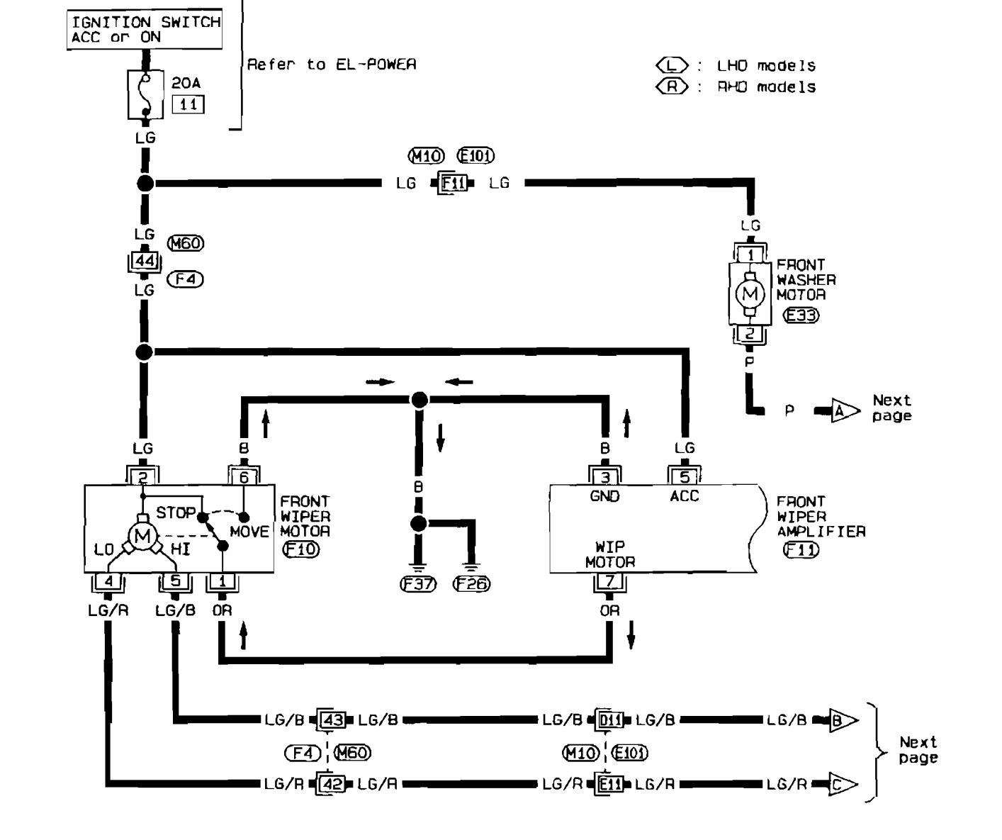
the original is wired like this:
page 1:
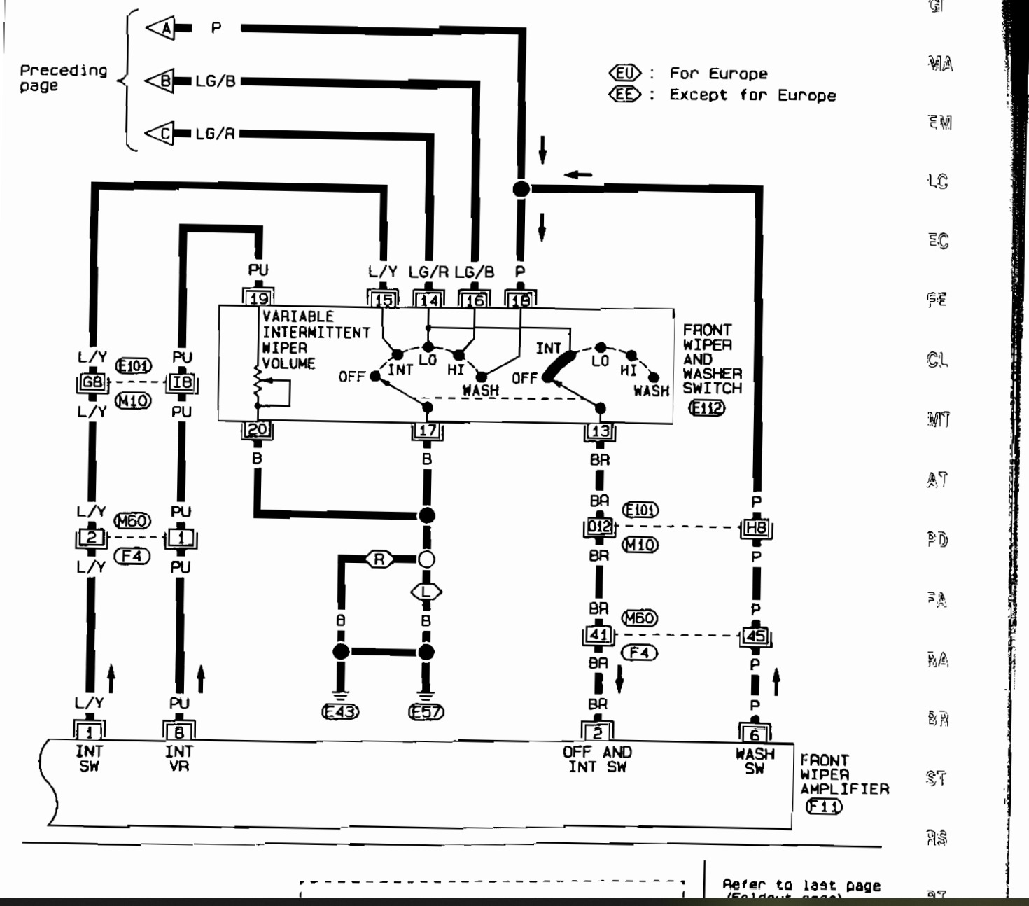
page 2:
the PDM i'm using is maxxecu PDM20 and it has wiper function for wipers high, wipers low and intermed,
Since it seems its just a DC motor, instead of wiring the front wiper motor with +12 from the LG and then grounding either lo or hi, i grounded
the LG wire(2) and i'm feeding power to either LG/R(4) or LG/B(5). the B(6) wire is grounded and OR(1) i'm using as wiper park signal. (altough its kinda inverted).
So i'm ditching the "front wiper amplifier" from the original setup and just using the PDM to run the motor.
The wiring seems to work, but i noticed thaat the wiper motor is drawing almost 15A on the low setting and only 5A on the high, this makes
me think something is not happy and will let out the smoke.
Any ideas what could be wrong ?
Yeeeeah 15 amps seems like a lot. I usually see maybe 4 amps with the motor running on a dry windshield.
For the Nissans I generally use a relay to flip the motor's ground path between Low and High speeds. I've found putting it backwards as you have done doesn't park in the same place, especially if the wiper linkages/bushings are worn.
yeah, just noticed the park issue also, which is frankly kinda bummer. Tried adding a internal output function which had a 0.1s delay on the activation to get it to park correctly, but it acutally goes over the parking limit. What i might do is just wire it the correct way around and just wire the high speed in. I can use the intermitten wiping motion for the lower speed and high when its actually raining.
Looks like the decision to only put DT connectors on my main harness and do the wiring to the OE connectors with small sub assys really pays out now, so easy to switch pin positions. :)
Alright, this one is now sorted. I switched from using two outputs from the PDM to using a single output with PWM.
Connection:
LG wire (2): PDM output
LG/B wire (5) : GND
OR wire (1): Wiper park, PDM input.
PDM setup:
Output configured as Controlled from ECU
CAN KB button defined as Momentary, function increases a counter.
PDM internal output 3 configured as follows: active if wiper park < 5V OR counter > 0
PDM counter configured as "reset at limits" min value 0, max value 6
ECU PWM output configured as: active condition: PDM internal output 3 > 0
duty table as follows:
counter: 0 = 70%
counter 1 = 60%
counter 2 = 70%
counter 3 = 80%
counter 4 = 90%
counter 5 =100%
So now depending on the counter value, the PWM is ranging from 60-100%, and then when the counter is 0, the pwm will be 70% until the wiper reaches the park position, then the output will turn off. So i have now multiple wiper speeds with only 1 output wasted from the PDM.
I really like this PDM and ECU combination when i can just combine the functionality like this.


