Sale ends todayGet 30% off any course (excluding packages)
Ends in --- --- ---
Ask questions about webinar lessons here. To see the Previous Webinars for a complete list of archives tuning webinars.
Electronic boost control can be used to adjust the turbo boost pressure, as well as the shape of the boost curve. Often electronic boost control can also help reduce lag, providing a wider powerband. Boost control however can be difficult to setup in order to get the best results. In this webinar we will be looking at the settings available in the Motec M1 range of ECUs and we will demonstrate how these can be configured on the dyno. For this webinar we will be using our Toyota 86 fitted with the Motec M150 ECU.
Watch the webinar lesson: How to set up Boost Control in a Motec M1
English Captions: Coming Soon
Ask your questions here in this thread.
Hi,
What is the best way finding correct duty cycle for different boost levels (in feed forward table)
using dyno - steady state or ramp runs?
There are a couple of options. My preference is to do this manually. I start with the PID gains set to zero and the feed forward table set to zero to get a feel for the minimum or wastegate boost pressure. Next I will start increasing the feedforward table by 5-10% at a time and doing a run on the dyno to see the effect. It's a case of making a small change and seeing how that effects the boost. After a couple of attempts you will get a feel for what sort of duty cycle change results in how much boost.
The other option is to use the integral gain to help you along with the time graph function. If you set the integral gain at 0.500 for example, this will make a change to the wastegate dutycycle of 0.5% per second per kPa error. What this means is that the integral gain will slowly adjust the duty cycle until you reach target. You can hold the engine at WOT in steady state on the dyno and the boost will step towards your target. Once it's reached your target you can simply transpose the wastegate duty cycle number from the time graph into your feed forward table.
Thank You for answer.
as You mentioned in webinar some cars need for linear boost (2wd turbo) - throttle position when boost is going up more!
is it case to case and need to check what boost is reached at constant TPS with just (spring - pressure) or +/- aproq 50% when start to go up in pressure?
hope You understand.
It's always a good idea to use throttle position as an axis on the boost aim table, particularly if the car has low traction. The tuning of this table will really depend on how much traction the car has, as well as how much power the engine produces. I always tend to start with low boost, somewhere close to the wastegate boost pressure and then slowly start increasing the boost targets at part throttle. The correct boost target will need to be confirmed by the driver as to where he/she is happy with the power delivery and throttle control of the engine.
Hey Andre, I just watched this webinar and had a quick question as I'll be setting up closed loop boost control for the first time on a Haltech Sport 2000.
Say you set your boost level to 14psi and get all your PID settings spot on will these settings still be spot on if I change the boost to 20psi or do the PID usually need abit of adjustment for different levels?
In my own experience the PID settings aren't that sensitive and while yes, in theory there may be some difference between the response at 14 psi and 20 psi, the closed loop system should be able to function adequately with the same PID gains.
When setting up your PID's do you find it best to do ramp runs or hold it under full load in steady state?
I always tune the gains using a ramp run, however before I call it done, I will also do some steady state running at 4000-5000 rpm and go in and out of the throttle repeatedly. This replicates how the car will be used when driven hard around corners (backing off and then accelerating again) and hence this is an area that the car may be prone to overboosting if your gains aren't right. If you can do this with stable control then you can be confident the boost will be on target in the real world.
Thanks Andre, I did this on the weekend and using the info from the webinars etc got it all to work great!
I did notice on the dyno it was working perfect with just about 0 overshoot, but when road testing in the morning it was overshooting and hitting the boost cut (the cut was set only 2psi higher then the targeted 20psi) But by reducing the base duty cycle (feed forward value) a couple % it cured the problem and still reached target and held nicely.
Next time ill try what you said with the Steady state and hopefully it finds things like above before getting out on the street.
Depending on how you have your dyno setup, often it isn't going to perfectly replicate the load applied to the engine when you accelerate out on the road. I do often find that it's necessary to reduce the base duty a small amount between what works on the dyno and what works on the road.
Hi Andre - in the webinar I think you mention BOOST ACTUATORY POLARITY depends on how it is "plumbed" up and wanted to confirm this is in reference to how the boost solenoid (actuator) is wired and NOT how the wastegate pressure lines are "plumbed".
I've been testing my configuration and was hitting boost cut on low Feed Forward values / duty cycles, so I switched the setting and on 15% it essentially mirrors waste gate only pressure. However, if I increase the Feed Forward values progressively e.g. to 20 or 25% my Boost Actuator Main Output Duty Cycle is still only hitting 15% (or doesn't seem to change). My minimum and maximum are 15% and 85% respectively. Based on the firmware help menu it seems the M1 will compensate for the polarity setting automatically and I shouldn't have to change the min and max based on polarity configuration. I'm sure I am missing something simple.
Thanks in advance
Edit: thinking through this more the solenoid wiring is not polarity specific and is either energized or not when the electrical circuit is complete.
So assuming the term “plumbing” is based on how the pressure lines are routed.
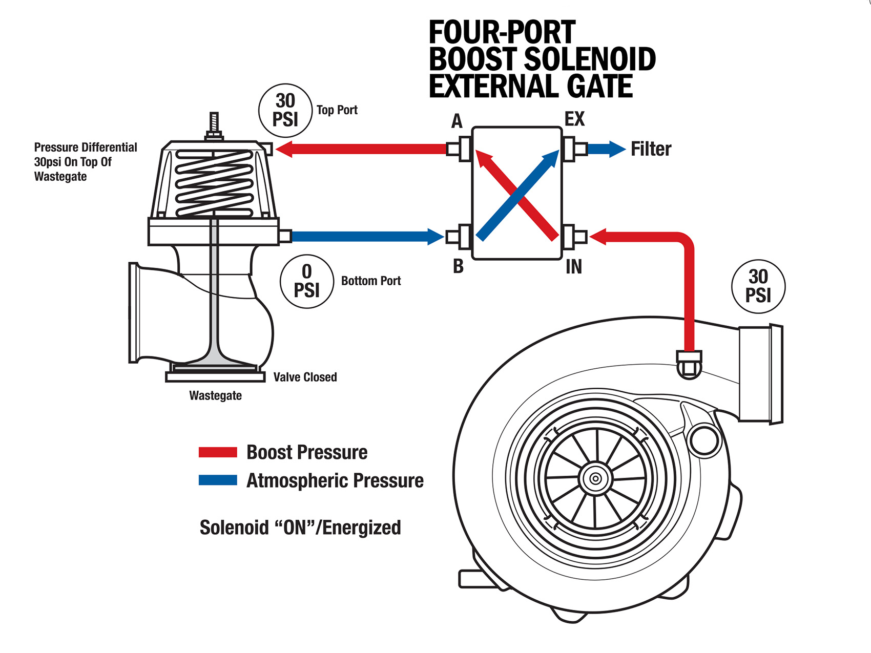
So in my case with a 4 port solenoid “plumed” like the Turbosmart instructions here:
https://www.turbosmart.com/wp-content/uploads/2011/12/WG_Powergate60.
When the solenoid is NOT energized the pressure/air flows to the bottom of the wastegate and the top of the gate is vented to atmosphere. This would generate the least boost or essentially the same as wastegate only spring pressure and is the most conservative since if something happened to the solenoid as a fail safe it would be at the lowest setting.
Conversely as the solenoid is energized it diverts air pressure from the bottom of the gate to the top of the gate helping apply pressure to keep the gate closed beyond spring pressure. Here is a good diagram I found:
https://dsportmag.com/wp-content/uploads/science-of-boost-solenoids-140-010.jpg
Hope this helps someone else.


