308 | Injector Scaling - Reflashing with Larger Injectors
Summary
Fitting larger injectors is a common upgrade when modifying a car, however scaling these new injectors correctly inside a factory ECU is a key step to getting your tune dialled in. In this webinar we’ll look at how this can be done on the Subaru platform using Ecuflash and Romraider.
| 00:00 | - Hey team, Andre from High Peformance Academy, welcome along to another one of our webinars and this time we're going to be looking into injector scaling. |
| 00:07 | We'll find out what that term actually means and why we need to understand it. |
| 00:12 | Injector scaling is something we're going to be doing a lot of when we're tuning any engine management system, factory engine management system where we have upgraded the injectors. |
| 00:22 | Essentially what this is is information that allows the ECU to understand the relationship between the pulse width that it delivers to the fuel injector and the volume of fuel that is delivered. |
| 00:36 | Why that's important is that understanding how much fuel the ECU is able to deliver for a given pulse width is critical in order to achieve a target air/fuel ratio. |
| 00:47 | Essentially what the ECU has is an input in the way of, most likely a mass airflow sensor if it's a factory engine management system, that's telling the ECU what mass of air is going into the engine and we're also telling it what air/fuel ratio to target and in order to achieve that air/fuel ratio it needs to know what mass of fuel to deliver, there's a relationship there between the fuel mass and the fuel volume but essentially this comes back to what pulse width do we need to deliver to the injector in order to achieve the correct delivered mass of fuel? So of course if we're dealing with a factory engine management system and everything's stock, all of that data for the factory injectors is going to understandably be correct. |
| 01:29 | But when we start running out of fuel system head room when we're modifying our engines, we're going to quickly find that we need to upgrade our injectors and this is where it comes to providing that correct information back to the ECU in order to get everything working again. |
| 01:45 | Now there's a couple of elements that go into this and it really depends on the type of engine management we are tuning. |
| 01:54 | Now we're going to be looking here at our version 11 Subaru STi, we're going to be using EcuFlash for making our tuning changes. |
| 02:02 | I can't actually make those changes live here, I don't have the time to do that and then show you the outcome but we'll be talking through what changes we make and how we go about them. |
| 02:11 | I'm also going to be using RomRaider for our logging. |
| 02:14 | What we'll look at here is also broadly applicable to the Mitsubishi range of Evolution vehicles because they work in a very similar way with the way they do their scaling. |
| 02:25 | So how does that scaling work? Well in these ECUs it's actually relatively straightforward, we've got two parameters essentially, we've got a scaling value and then we've got a latency table and so that we sort of have an idea of what that looks like, let's head over to my laptop screen. |
| 02:43 | This is our Subaru STi ROM open and I've got everything open here so it all sort of all looks a bit of a shambles but we don't need to worry too much, I'll just come down until I find my injectors tab, injectors menu and that's the one here and basically the two pieces of information that we want, I'll just open them up here side by side. |
| 03:05 | First of all, primarily we've got our injector scaling value. |
| 03:10 | In EcuFlash this is displayed in cc's per minute, obviously 562 cc's per minute and then we've got our latency table over here on the left hand side. |
| 03:21 | This is a 3D table interestingly enough, it won't always be but the horizontal X axis there is our battery voltage and then the manifold pressure is our vertical axis. |
| 03:33 | What you can however see is that that vertical axis, the manifold pressure essentially isn't being used, the 3 rows of data are the same so it's there but it's not actually being used. |
| 03:44 | In essence, this system though is a manifold pressure referenced fuel pressure system. |
| 03:52 | Bit of a mouthful, essentially what it means is that as the manifold pressure goes up and down, so too does the fuel pressure. |
| 03:57 | The key element with that is that this system should maintain a consistent differential fuel pressure which is the difference between the fuel pressure above the injector, manifold pressure below. |
| 04:10 | The key for that, why that's important is that our dead time or latency will vary with not only battery voltage but also the differential pressure across the injector. |
| 04:19 | As we raise the fuel pressure or the differential pressure, that makes it harder for the injector to open and flow fuel and hence our deadtime or latency value increases. |
| 04:31 | Now let's jus,t take a moment now to talk about latency deadtime, battery offset is another term you may hear it reffered to as. |
| 04:39 | We need to understand what this actuall means so that we can go ahead and actually do our job properly. |
| 04:45 | So you may consider that when the ECU asks the injector to open, it provides a pulse width, just essentially turns the injector on by earthing one side, it's got 12V going to the other and fuel starts flowing. |
| 04:58 | The problem is that this is a mechanical device so the valve inside of the injector has a mass, we've also got the fuel pressure that I just talked about which is trying to force the injector closed. |
| 05:11 | So there's a latency or a lag between the ECU signalling the injector to open and then the injector actually opening. |
| 05:20 | And then at the the other end of the scale, when the injector closes, it also doesn't close instantaneously, there's a very small delay there so latency, the easy way I like to explain this is the difference in time between the length of the pulse width that the ECU provides the injector and the length of time the injector is actually open and flowing fuel. |
| 05:42 | And if we don't account for this properly, it's going to bring in some really weird problems with our fuelling, particularly as our battery voltage changes and particularly as our pulse width changes, specifically if we're asking for a correction for example, maybe we're trying to do a correction based on our inlet air temperature, if our deadtime isn't correct, we're going to be compensating the wrong value of our injector pulse width and hence our corrections aren't going to work properly so it brings in all sorts of weird problems with our tunability. |
| 06:14 | On a bit of a tangent here, because a lot of people put a lot of emphasis on deadtime values, particularly in the aftermarket ECU industry. |
| 06:23 | I'll just point out that when I first started tuning, there were a number of ECUs that actually completely ignored deadtime. |
| 06:31 | Simpler times, people didn't really have a good comprehension of what was going on with the injector and how it operated and they just blindly ignored that deadtime. |
| 06:39 | Now yes the results were not as nice as what we can get these days with proper understanding, proper ECUs with full compensation for deadtime but we got the engines running and they ran relatively well so there's levels to this. |
| 06:55 | Where it gets more important though is when we start getting sophisticated factory engine management systems. |
| 07:01 | If we start building in errors into the systems, there's a lot of knock on effects from those errors so we really do want to do as good a job as possible when we are doing this. |
| 07:11 | Now we are focusing obviously on our Subaru STi but just for the sake of completeness, what I want to do is just show you how this data is used in some other factory engine management systems where they get a little bit more granular and down in the weeds with this. |
| 07:28 | So let's have a quick look over at VCM suite from HP Tuners and I'll just show you, just close this one down, don't need two open. |
| 07:41 | Right, so this is a calibration on an E38 engine control module for a 2006 Holden Commodore SS. |
| 07:52 | And, bunch of information here, really what I want to show you here is we're on this fuel tab and we've got all of these parameters here for our injector control. |
| 08:01 | So for example, if we look at our flow rate vs pressure, so this is essentially the injector scaling if you like. |
| 08:10 | We're telling the ECU what the flow rate of the injector is going to be relative to the pressure delta. |
| 08:17 | Then if we come down here we've got also our offset, this one here, offset vs pressure vs voltage so this is our injector deadtime and then we've also got another parameter here which is called a short pulse width adder, which is this little guy here and basically this defines the difference between the theoretical perfect linear flow of the injector and what we find is that at very small pulse widths, typically what we get at idle, the actual flow from the injector varies from this a little bit so basically this is a adder that goes in to basically correct it. |
| 08:59 | So obviously this is getting quite down in the weeds as I mentioned, and GM are trying to do a really good job of this and get really really accurate control, not every engine management system, factory engine management system does it to this degree, like the STi we've just looked at but I just want to mention that this exists. |
| 09:15 | If we're dealing with this, there's pros and cons with it. |
| 09:18 | On face value you might be thinking well where on earth are you going to get this sort of data? Well this really comes down to purchasing your injectors from a supplier that can give you this data. |
| 09:29 | For the likes of Injector Dynamics, they do a really good job of this. |
| 09:33 | For all of their injectors, you can download data in GM format or Ford format, Ford do a slightly different job of characterising their injectors but essentially we can have our flow rate data here, then we've also got the offset table that we looked at just earlier, then we also have the short pulse width adder. |
| 09:54 | It's in a few different formats depending on what particular controller you are dealing with but the nice aspect of this is it's literally copy and paste just copy the relevant table, paste it into your VCM Editor or EFI Live, whatever you're using, job is done and because it does such a good job of basically characterising the injector flow versus injector pulse width, you can go to a 1000cc injector, put the right data in, the engine will start up, it's going to run exactly the same, your short term and long term fuel trims are going to be probably within a couple of percent of what you were seeing stock, it is that good. |
| 10:33 | So obviously when it works like this, it makes our job as a tuner much much easier. |
| 10:39 | Alright just give me a second, we'll just head back across to my notes now. |
| 10:47 | Now when we are dealing with the likes of the STi, we just looked at the data there for the injector scaling which looks like a number that is very very close to our injector size and in most instances it's going to be there or there abouts. |
| 11:05 | Depending on the exact resource you look at for these version 11 STis, I haven't actually flow tested the injectors myself, I think most people sort of rate them or expect them to be 550cc so we're there or there abouts, the scaling number is 562 but in the Evo world, there's a bit more of a variation between the scaling number and the size of the injector. |
| 11:24 | What I mean here, what you need to understand is the scaling number will be pretty close to the injector flow but it's not necessarily going to be exact. |
| 11:33 | The latency, I usually find there's a bigger variance as well so it can be very tempting to go to your injector manufacturer or supplier and they'll provide data, copy and paste that data in and kind of like we just looked at for GM and it doesn't quite work that simply. |
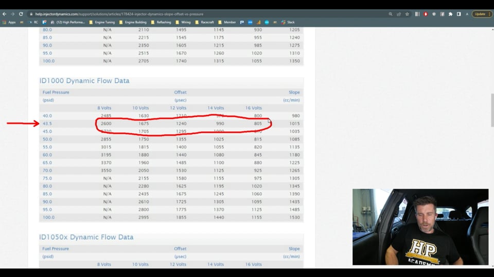
| 11:51 | So let's have a quick look here, this is the data for the injector ID1000 injectors and yeah again we can use this data for an aftermarket ECU and that's what we do but it's not going to work perfectly if we use this just blindly and copy and paste. |
| 12:07 | So what have we got here? We've got the offset numbers, latency, battery voltage, whatever you want to call it. |
| 12:14 | In this case they've called it offset, obviously Subaru call it latency but 8, 10, 12, 14 and 16 volts and then we've got what Injector Dynamics have referred to as slope, basically flow in cc's per minute. |
| 12:25 | Now the other aspect of this is we do need to know what our fuel pressure is, our differential fuel pressure. |
| 12:32 | In a port injected engine, typically in factory form it's going to be 3 bar or 43.5 psi, that is what the Subaru base fuel pressure should be. |
| 12:43 | So what that means is that we are looking at this row here. |
| 12:48 | So again can be really tempting just to copy the data from this table here for that row and paste it in. |
| 12:54 | And again it's not going to necessarily work perfectly, we'll show you how we should be developing that. |
| 12:59 | What we can see is at 43.5 psi, we should be expecting about 1015cc per minute of flow. |
| 13:08 | Now there are a few things to watch out for here as well that can trip you up. |
| 13:14 | The scale, you can't scale the injectors for your calibration and your mass airflow sensor simultaneously. |
| 13:24 | So what do I mean by this, we've talked about why we would upgrade injectors but at exactly the same time when we maybe fit a larger turbocharger, increase the boost dramatically, we can get to a situation where we max out the flow through the factory mass airflow sensor, these are typically a 0-5 volt sensor and they will only measure a certain mass flow of air before they just tap out and flatline at 5V and we can't measure anymore. |
| 13:51 | Essentially making it impossible to tune the engine properly beyond that so a common modification is to fit a larger mass airflow sensor tube and basically by increasing the diameter of the tube, we're increasing the mass airflow through that sensor for the same voltage. |
| 14:08 | So extending our range. |
| 14:09 | So this requires us to rescale the mass airflow sensor calibration curve. |
| 14:13 | This is a topic for another day and in fact if you search in our archive we have covered this in the past but the important thing is if we upgrade our mass airflow sensor tube, and we upgrade our injectors, we're going to end up in the situation where we've got this error between our commanded air/fuel ratio and our delivered air/fuel ratio and we're not going to know where to correct it. |
| 14:37 | We could correct it with the MAF scaling or we could correct it with the injector scaling but we don't know which is wrong. |
| 14:43 | So it's really important if you're going to fit larger injectors that you have a known good calibration for your mass airflow sensor first. |
| 14:52 | It is a bit more messing around because if you are going to do both, basically you have to either stick to stock injectors rescale a mass airflow sensor and then upgrade injectors or you need to go the other way around, keep the factory mass airflow sensor, scale in your new injectors and then upgrade the mass airflow sensor. |
| 15:12 | Now for those who are doing this professionally though, what you'll generally find is that you'll stick to one type of injector and once you've gone to the trouble one time of developing the calibration numbers for our version 11 STi for example, you're not going to need to do that every time, provided you do use the same injectors, then of course you can use the same data for subsequent tunes so it's kind of a 1 time thing and it does pay to spend the time and properly calibrate this and get these numbers as good as you can. |
| 15:45 | The other aspect here is that the scaling numbers will be affected by ethanol content, they're also going to be affected by fuel pressure so these are a couple of things that can end up catching ourselves out. |
| 15:57 | Particularly if you've going to be running a dedicated E85 for example, that's going to massively affect the scaling number you need for your injectors so using the 1015 example that I just gave you for the ID1000, we're not going to be anywhere near that so we're going to be adjusting the scaling number to suit our ethanol content. |
| 16:20 | And lastly fuel pressure. |
| 16:21 | I mentioned that the base fuel pressure for the Subaru, typically 43.5 psi. |
| 16:27 | And if you upgrade the fuel pump to a high flow pump, what you'll quite likely find is that it'll actually bump up the base fuel pressure slightly, not a heap but you basically can overwhelm the return flow through that factory regulator and you might find that your base fuel pressure goes up a few psi which then of course means that your injectors will flow a little bit more fuel so these are just subtle things that you do need to understand, they will come into play and they will influence your tuning when you are scaling your injectors. |
| 17:00 | Alright I'll just get back to my notes here. |
| 17:05 | Now that we've got a bit of a background here, I'm going to talk about the process that we're going to go through. |
| 17:12 | So essentially we're going to gather two data points and we're going to use our logger to look at our closed loop trims and this is going to allow us to assess the quality of our injector scaling. |
| 17:25 | Now what do I mean by this? How does this all work? So the premise here is that the closed loop trims show us how accurate or inaccurate our injector scaling is. |
| 17:35 | And why we use two points, one at idle and one at higher load or higher RPM, light load, we're not going to be at wide open throttle but we might want to be using 3500, maybe 4000 RPM. |
| 17:48 | Part throttle, we still want to be in closed loop so we've got those trims operational but what we want to do is look at two very different injector pulse widths. |
| 17:56 | And why that's important is that the injector latency, let's say we've got injector latency in our stock calibration of 0.8 ms at 14V, probably be pretty typical. |
| 18:11 | And at idle, maybe we've got an injector pulse width, total injector pulse widths of 2 ms so 0.8 is a large portion of that 2 ms pulse width so if we've got an error in our latency it becomes very apparent, it's much more powerful at idle. |
| 18:29 | If we go up to higher RPM and maybe our injector pulse width is now 6 or 7 ms, obviously now our 0.8 ms deadtime or latency, it's a much smaller proportion of that overall pulse width so it has less effect, the error is less. |
| 18:46 | So what we're looking at here is, well what we need to understand I should say is what these numbers mean. |
| 18:54 | So again we're looking at our combined short term and long term fuel trims to guide us. |
| 18:58 | If the low and high pulse widths tests both show positive trims, that means that the closed loop system is adding fuel. |
| 19:09 | Obviously because it's adding fuel, this means that we are naturally a little bit lean. |
| 19:13 | In other words, if we didn't have those closed loop trims active, we would be leaner than our target, meaning we need to add fuel. |
| 19:20 | In order to add fuel, what we want to do is reduce the scaling number. |
| 19:25 | Why we reduce the scaling number is essentially it's telling the ECU that our injector that we've fitted to it is smaller. |
| 19:33 | And if the injector is smaller, the ECU obviously is going to open it longer to get the volume of fuel that it wants so that's going to increase our fuel delivery. |
| 19:42 | So that's going to fix that problem so that's what we do if our trims are positive in both the low and high pulse width tests. |
| 19:51 | On the other hand, naturally if our low and high pulse width tests are both negative, this means that we are rich and the closed loop system is removing fuel. |
| 20:00 | Obviously what we want to do here is the opposite, we need to increase the scaling. |
| 20:04 | Essentially tell the ECU that we've fitted a larger injector that will mean that for the same volume of fuel that the ECU wants, it's going to provide a shorter pulse width. |
| 20:13 | OK so that's when we're overall rich or overall lean, this will be our first modification that we make to get our scaling into the ballpark. |
| 20:22 | Then we can start looking at our latency table and the way we do this is we look at our idle pulse width, our idle trim I should say, versus our higher load trim. |
| 20:33 | So if our high load trims are good, and by good, I'll deal with this shortly, I'm meaning maybe +/- 2-3%, and our idle trim is negative, what this means we need to do is reduce the latency values. |
| 20:50 | Of course if the trims at idle are positive, this means that we need to add latency. |
| 20:54 | Now this is an iterative process, you are not going to get this right in the one shot so generally it'll take maybe 2-4 attemps and of course there's some knock on effect here. |
| 21:07 | While I said that the latency has less effect on our fuelling at higher load, higher RPM. |
| 21:14 | of course it's still going to have some effect so we need to obviously, when we make a latency change, go back and check that our higher pulse width, fuelling trims are still on point. |
| 21:25 | If they're OK then we don't need to touch the scaling and we can just work on our latency so there's a bit of toing and froing with this, you're not going to get it necessarily right in one go. |
| 21:37 | Alright so, hopefully you're still following me here, remembering we will be having questions as well so if you've got any questions, you can ask those and we'll answer those at the end. |
| 21:46 | So what we're actually going to do, the process we're going to go through here. |
| 21:50 | What we're going to do where possible is we're going to start by testing the current calibration with the original injectors. |
| 21:59 | And why that's important is it allows us to see what our trims were like with everything stock. |
| 22:06 | This will also allow you to kind of see if there's any built in problems that could end up tripping you up. |
| 22:13 | So there's a couple of elements here. |
| 22:15 | While I've talked about fitting a larger mass airflow sensor tube, obviously that's going to affect the MAF calibration. |
| 22:22 | I've actually seen the MAF calibration also affected by seemingly subtle changes to the air box, even the air filter element. |
| 22:30 | So basically when the factory calibrate the mass airflow sensor scaling, it's done for the entire inlet track. |
| 22:37 | Everything from the inlet to the air box, the air box itself, and then the plumbing up to the throttle body so basically, or turbocharger as the case may be. |
| 22:46 | So basically any time you change any of those components has the potential to affect your mass airflow sensor scaling so that's why we want to check this. |
| 22:56 | Also comes down to things like ethanol content and the point I made before if you've upgraded the fuel pump, you may not even have a clue that the fuel pressure is actually increased over what it should have been so you'll be seeing trims that shouldn't necessarily be there and we want to fix this sort of a problem first and foremost before we get onto adjusting our calibration for the injectors, otherwise we're trying to fix a baked in problem. |
| 23:23 | Now what should these trims be? Well generally I like to have the trims within about +/- 5%, obviously the closer we are to 0 the better but there's no point beating yourself up there either, you're never going to get them absolutely perfect and they do move around so essentially you might do one test and see the trims as +1 or 2% and come back an hour later and do essentially the same test and you might find that trim is moved by 1 or 2% so as long as we're within that +/- 5%, I'd probably prefer to be closer to +/- 3%, we're good to go. |
| 24:00 | Alright then we're going to obviously swap our injectors, we're not really talking about the mechanical aspect of swapping the injectors but obviously some precautions around the fact we are dealing with fuel here, should go without saying, one of the key ones we always want to do is bleed down the pressure in the fuel system before you actually remove the fuel rails so you don't end up spraying fuel needlessly everywhere and of course we want to test the fuel system as well once we've got the new injectors installed and make sure that we don't have any leaks. |
| 24:28 | Once we've done this, we're going to adjust the scaling value to suit. |
| 24:33 | Now what should we do with that scaling value? Well a good place to start is from a manufacturer's data there. |
| 24:39 | So we know that in the case of our STi, let's just pop back to our calibration, we had that value of 562.45, we're going to a set of injectors that theoretically should flow 1015 cc per minute at 43.5 psi so I would start by simply changing that to 1015. |
| 24:59 | Now it almost certainly won't be right but what we're trying to do at this stage is just get it close enough that we can actually start the car, get it running, we're not going to end up fouling the spark plugs in a matter of moments and then we can get the car back into closed loop mode and actually start gathering some data to fine tune that number. |
| 25:17 | So 1015, that's where I'd start, obviously the injector manufacturer will give you data for different fuel pressures so you can account for that as well. |
| 25:26 | Latency data at the moment, we are going to leave untouched, it's only the scaling that we want to change. |
| 25:34 | Now there are some other tables that we are also going to need to adjust. |
| 25:40 | Specifically there are some tables that are injector pulse width based as opposed to a percentage so for example, I can't remember all of them off the top of my head but I think we have this table here for example, our closed loop to open loop transition with delay, base pulse width. |
| 26:03 | This table here is based on injector pulse widths so we want to reduce these, so obviously we've fitted larger injectors so all of the tables that are pulse width based, and there's about 5 or 6 of them that we want to adjust. |
| 26:16 | We need to reduce those down. |
| 26:18 | Now what factor do we use here? Well we've almost doubled the injector size, gone from 550 to 1015 so you might think on that premise that halving those numbers would be a good place to start. |
| 26:30 | It makes sense, in reality from testing, going to 50% actually is a little bit over bearing so we're going to reduce that down a little bit, I normally start with a factor of about 30% reduction and that seems to work quite well. |
| 26:44 | Again I can't quite remember all of the tables, I should have actually prepped that before this, there's about 5 of them but basically the tables that are injector pulse width based, here's a couple more that are open in front of me so I will show you. |
| 26:58 | The fuel and cranking, this is a good one that if you don't understand that this needs to be changed, you're going to end up potentially flooding the engine. |
| 27:08 | So we've got a few of these, we'll just open these up, don't probably need to open all of them but you've got A, B, C, D, E and F, I think G and H in this are set to 0, they're not used. |
| 27:21 | So again we'd just highlight the entire table and multiply that by 0.7 which is obviously making the reduction of 30%. |
| 27:29 | So that's what we need to do if we've got a table that is specifically injector pulse width based as opposed to being a percentage of the fuelling for example, just get our injector latency back open. |
| 27:41 | Alright so at this point we should have a calibration that won't be perfect but it's going to be enough to get the engine up and running so we want to flash that into the vehicle. |
| 27:50 | And then we want to get the engine physically up and running and allow it to come up to normal operating temperature. |
| 27:58 | So particularly after you have flashed the ECU for a period of time, the ECU will actually not run in closed loop mode. |
| 28:05 | It needs to basically run for a period of time so we want to make sure that it is operating in closed loop mode, I'll show you how we know that that's happening in a moment. |
| 28:14 | And we also want to make sure that we allow any heat soak to dissipate. |
| 28:20 | This is really important and it affects you particularly if you are road tuning. |
| 28:25 | I should have mentioned this is something that can be very easily done on the road, you definitely don't need a dyno to perform this. |
| 28:32 | But what you're going to be doing a lot of when you are road tuning is driving the car, everything's hot, the engine's hot, you're going to pull over to the side of the road, you're going to make some changes, look at some logging, make some changes and then flash that into the ECU so you might be sitting on the side of the road for 5 or 10 minutes while the engine bay is heavily heat soaking. |
| 28:52 | Then when you get up and running again, if you start gathering data straight away, you're going to be gathering that data in a fairly non realistic form, everything's heat soaked and it's not at a normal operating temperature and this can affect our results. |
| 29:06 | So basically you want to drive the car and get airflow through, get rid of our heat soaking, give it sort of a good 3-5 minutes of driving before we start gathering that data. |
| 29:15 | Once we've got that, we can log at idle and at a higher RPM point as I mentioned and look at what our combined short term and long term fuel trims are doing. |
| 29:28 | Then we use that information that I just mentioned before, basically, whether our trims at idle and our higher pulse width are all positive or all negative and then we're going to start by adjusting our scaling. |
| 29:40 | Now we can use the combined error to guide us on the magnitude of our changes as well so let's say for example, a really nice situation would be that our combined trims at idle and at 3500, 4000 RPM are 10% positive. |
| 29:58 | Well what we could do then is use that error of 10% and we would make a relevant 10% change to our injector scaling. |
| 30:06 | Remember if our trims are positive, this means that we are lean so we need to tell the ECU that the injectors are smaller so it provides more pulse width to get the fuel in. |
| 30:17 | So what we would do is simply reduce our injector scaling value by 10%. |
| 30:22 | Now still possibly not going to be perfect but it's going to be a pretty quick way of dialling that in so we always want to take note of what that percentage error is so we can use that to help us with our scaling. |
| 30:33 | So we should be able to get our scaling, particularly at higher RPM dialled in within 1 iteration, that shouldn't be very difficult at all because as I just mentioned, we know what that percentage error is. |
| 30:44 | Then what we want to do is focus on our idle trims, look at what our idle trims are doing and then we can start dialling in our latency. |
| 30:52 | As I mentioned there, we do have that back and forth between our latency and our injector scaling so every time we change the latency, we still need to check our scaling is still in the ballpark at higher RPM. |
| 31:06 | Now the other element that's worth discussing here, if we come back into my laptop screen, is our latency values at the different battery voltages. |
| 31:16 | And this is where basically the technique of dealing with this is really up to the individual. |
| 31:23 | I personally, when I'm scaling injectors like this I will just make an overall change to the entire table, let's just have a quick look whether we can see the general shape of this table. |
| 31:35 | So we can sort of see that kind of exponential shape, obviously the latency value increases at lower battery voltages and that's because there's less electrical energy to get the injector to open so it takes longer to open. |
| 31:49 | So that general shape, we will see with any injector, the shape doesn't change. |
| 31:54 | Yes the specifics of the number will but the shape is still going to be pretty much what we've got right here. |
| 32:01 | Now the other thing we need to understand is with our alternator, our charging system in our car, it is designed so that it will maintain, or should if it's working properly, maintain our voltage pretty much bang on 14 volts, in fact sort of 13.8 to 14.2 is where we normally are. |
| 32:17 | So what I'm getting at is, 14 volts, this is really the key critical column in this table that we want to know is right and if we find that we need to increase this entire table by let's say 10%, well sorry if we find that we need to increase our latency at 14 volts by 10%, what I would do in this instance is just highlight that entire table and make that change. |
| 32:42 | We can use the multiply symbol, 1.1 is a change of 10% and that will make that change. |
| 32:49 | Now is that going to be perfect? Is that going to be absolutely correct? Probably not but the reality is we are going to be so close, it's probably not going to be worth worrying about because we shouldn't ever really be down at 11.5 volts unless we've got failure of our alternator. |
| 33:09 | The alternative, if you do want to be a little bit fussier though is that you could disable the alternator, pull out your alternator fuse and that will bring your voltage down to probably 12, 12.2 and then as the battery voltage drops down, you're sort of going to end up down in this lower voltage area. |
| 33:28 | So you could get a pretty good feel for what the 11.5 volt column is, you can turn on your headlights, your fan etc to increase current draw and that will also drop you down further. |
| 33:40 | Again, up to the individual, personally I do not see the need for doing this. |
| 33:44 | Just scaling the entire table is typically going to get you a really good result. |
| 33:50 | So once you've done that, once you've got your trims within that +/- 5%, but ideally maybe a little bit tighter than that, as I said I'd love to be probably +/- 3% at both idle and higher RPM. |
| 34:06 | We also need to just test our wide open throttle performance during a ramp run or at a full throttle acceleration run and log the air/fuel ratio and actually just see how that's relating to our commanded. |
| 34:18 | In the Subaru and the Mitshubishi ECUs we generally find that if we're within a few percent, that's good enough and then from there rather than trying to fix that with mass airflow sensor scaling or our injector scaling, I would fix any remaining errors just in the specific region of our fuel, open loop fuelling target tables and that will get us where we need to be. |
| 34:42 | Alright we'll move into questions really shortly but let's just have a look at our RomRaider logging here and we'll have a talk through the process. |
| 34:52 | Now this is a pretty good example of what not to do. |
| 34:55 | So you're going to have to trust me a little bit here but let's just talk about this logging for a moment. |
| 35:00 | We've got all of our data here that we are logging, I've actually got a few parameters that are probably unecessary for our demonstration today but what we want to do primarily is we want to log our AF correction number 1 and our AF learning number 1 and this is essentially in Subaru lingo, AF correction number 1 is our short term fuel trim and AF learning number 1 is our long term fuel trim. |
| 35:26 | So we can see our current values here and like I said, little bit outside of that 3-5% that I mentioned, what we've got here is a long term trim, it's just changed, to 8.6% and our short term trim is 3%. |
| 35:40 | So basically we've got an overall trim, because these are cumulative, it's actually going up while I'm talking, we're about it's changing all the time, it's pretty hard to keep up with, let's call it 10%, it's just gone to 0 on our short term, these trims do move around so we've got a 10% trim at idle which again is not what I want, it's not ideal but we do need to add the caveat here that, I have been sitting here for probably half an hour, 40 minutes at the moment with the engine running, I've got no fans running so we've got that exact situation that I talked about which we don't want of heat soak. |
| 36:16 | So have a look at how these trims work again shortly. |
| 36:19 | We've also got our air/fuel ratio sensor 1 so this is our front sensor in the Subaru, it is a wideband sensor so we can use this to a degree for our tuning, we can see I'm displaying this in lambda, it's sitting at 0.99, obviously we're closed loop and idling so lambda 1 is pretty much where we're targeting. |
| 36:35 | Another parameter or monitor we want to look at is our closed loop to open loop fuelling and this is just to basically prove that we are in closed loop mode which is a value of 8 or a status of 8 so if we aren't seeing that value there, we are in open loop mode so obviously at that point we can't really use the short term and long term fuel trims. |
| 36:59 | We've got our closed loop fuelling target is our next value, obviously 0.99 lambda there, coolant temperature, obviously again bit hot here at the moment. |
| 37:08 | Again we can just monitor this and if we like our intake air temperature, just make sure we are seeing realistic numbers that are what we'd expect. |
| 37:15 | We want to see our engine speed, this is helpful for making sure that we are repetitive with our testing and process. |
| 37:24 | We've got our mass airflow sensor voltage and our mass airflow and this is probably more useful for when we are scaling our mass airflow sensor but it can also help if we are on a dyno to make sure that every time we test our higher RPM load point that we are at the same mass airflow sensor voltage and RPM so we're getting really consistent and repeatable results here. |
| 37:47 | We've got our injector pulse width so we can actually see what our injector's doing. |
| 37:53 | We've got our final base fuelling, essentially the same as what we looked at before and then a few other aspects that I won't even bother talking about. |
| 38:00 | Alright so obviously, as I mentioned, not everything's quite where it needs to be here at idle but let's bring ourselves up to 3000 RPM or 3500 RPM and we'll see what we're looking like there. |
| 38:16 | I've just turned on the fan as well which hopefully will help us a little bit. |
| 38:20 | Now a point to make here is that when we first get the engine up and running after we have flashed it, I've mentioned the heat soak element there but we also need to run the engine for long enough for our trims to stabilise so they will typically move around a little bit initially and over the period of maybe sort of a minute or two, we should get stable numbers so we can see here, looking at our RPM, sitting at about 3200 RPM, this is looking a little bit better now, got our fan on, you can see our total trim there is sitting at about 2-3%. |
| 38:56 | What will happen is we'll start with a short term trim because that is an instantaneous response to an error in our fuelling and if that error, if that short term trim stays in this case positive 3%, if it stays there for long enough, what that's going to do is over time, transfer through to our AF learning 1, our long term trim, we can see that's happening. |
| 39:15 | At the same time we've just had a weird little spike in our short term fuel trim and it's jumped up to 6 or 7%. |
| 39:21 | And again this is really what I was saying we need to allow the engine to run for long enough so that we've got nice stable results and everything is consistent, we don't want to get a flash in the pan look at a value and then sort of take that as gospel so it is important to allow the engine sufficient time to run. |
| 39:39 | Alright hopefully that's explained the process, again iterative, not very difficult, just to recap, make sure that we are dealing with a known good calibration, make sure that we haven't got a MAF calibration that's out or try to calibrate both our mass airflow sensor and our injector scaling simultaneously, can't be done, need to do one and then the other. |
| 40:05 | Process there is then check that our scaling, our short term and long term fuel trims are at least in the ballpark with our existing calibration and mass airflow sensor injectors, make sure that we don't have any baked in errors that are going to trip us up later on. |
| 40:19 | Swap the injectors, do our scaling initially, just based on the size of the injector that we are fitting then once we've done that, address any other tables like our cranking enrichment tables, that are based on injector pulse width, reduce those by a proportion based on our injector size, flash that into the ECU, get it up and running, allow it to get back into closed loop mode, get rid of any heat soak, look at our fuel trims at idle, look at our fuel trims at a higher RPM point then we need to adjust our scaling to suit. |
| 40:53 | Once we've adjusted our scaling, we can then look at our latency and adjust that to suit, iterative process, aiming for sort of 3-5% positive or negative combined trims. |
| 41:04 | Alright let's have a look at our questions and we'll see what we've got. |
| 41:16 | OK so Erica's asked, is latency that I'm talking about the low slope? Talking about when you are rich on the on idle but OK in the RPM, you increase the latency? Low slope and latency are very different. |
| 41:31 | So low slope, I touched on this, there's a nice diagram which I wish I'd pulled up but I don't have it handy, which really demonstrates this, basically as far as the ECU is concerned, it's really expecting that the flow of the injector is going to be a straight line relative to the pulse width. |
| 41:50 | That's what it's expecting. |
| 41:52 | The reality isn't quite the case and down in the low pulse width area there's going to be an area of non linear flow and that's this sort of low slope area that you're talking about. |
| 42:04 | Ford do a different way of specifying their injector characterisation than GM. |
| 42:09 | They have a high slope and a low slope, the high slope is the linear area of injector operation and the low slope is in that low injector pulse width, non linear area. |
| 42:21 | So in GM lingo, that is fixed with the short pulse width adder table, in Ford lingo that is fixed with the low slope characterisation data. |
| 42:31 | So it's separate to latency, it is another characteristic of the injector. |
| 42:37 | In the case of the Mitsubishi ECU and the Subaru ECU, it actually ignores that, well the one that we are using, it ignores the short pulse width adder. |
| 42:49 | Manitou Black's asked, MoTeC injector characterisation is a full table of pulse width vs fuel delivery in microlitres, does this allow accurate fuel delivery in the low pulse width with the non linear range? Yeah that's just MoTeC's way of doing their non linear short pulse width area. |
| 43:06 | As I mentioned, GM do it with a short pulse width adder, MoTeC actually do it with a full 4D table vs differential pressure, battery voltage and injector flow. |
| 43:17 | Can't quite remember if that's right but yeah basically you've got that full table there. |
| 43:22 | Another question from Manitou Black's asked, on an ECU like that has deadtime value but no low pulse width adder, should I set my deadtime as when the injector first opens or when the flow becomes linear? OK neither, so the deadtime remember, it's the difference between the time that the injector is open and flowing fuel and the pulse width that the ECU has actually provided. |
| 43:51 | So it's not to do with the non linear region, it's not to do with the minimum pulse width, it's a separate element all together based on the design of the injector, the inertia, the time it takes for the internals to start opening and moving and then also the battery voltage because that's the electrical energy provided to the injector to open it as well as the fuel pressure which I already mentioned, that fuel pressure is really trying to force that injector closed. |
| 44:21 | So yeah very separate terms there. |
| 44:24 | That looks like it's all of our questions for today. |
| 44:28 | Remember for our members if you are watching this at a later point in our archive and you've got further questions, please ask those in the forum and I will be more than happy to answer them there. |
| 44:40 | Thanks for watching and hopefully we can see you next time. |
Timestamps
0:00 - Introduction
0:12 - What is it and why do we need it?
2:26 - Subaru STi | Scaling and latency tables
4:31 - What does latency/deadtime/battery offset mean?
7:11 - GM | Short pulse width adder
9:18 - Injector data
10:49 - Manufacturers' numbers won't necessarily be right
13:09 - Can't scale injectors and MAF simultaneously
15:45 - Scaling will be affected by ethanol content and fuel pressure
16:20 - Be aware of base fuel pressure changing
17:05 - Gather data points to assess scaling
21:46 - Scaling process
31:06 - Latency values at different battery voltages
34:42 - RomRaider example
41:16 - Questions


