001 | Link G4 / ViPEC iSeries new VE Fuel Model Explained
Summary
Link / ViPEC have just released a major firmware upgrade (5.2.2) applicable to both the Vipec i-Series ECUs and the Link G4+ ECUs. One of the fundamental changes in this firmware revision is to the fuel model. While the traditional millisecond-based fuel model that Link/Vipec users would already be familiar with is still available, a new ‘modelled’ or volumetric efficiency based fuel model is now available as well as advanced integration for flex fuel/dual fuel compatibility.
In this webinar we will look at these changes, what you need to know, what you need to do differently, as well as how they can benefit you and provide a more stable and accurate tune. For this webinar we will be using our Nissan 350Z with a Link G4+ plug-in ECU.
| 00:00 | Thanks for joining us. |
| 00:01 | It's Andre from the High Performance Academy. |
| 00:02 | And we're going to look today at the new Electrons firmware version 5.2.2 applicable to both the Link G4 Plus and the Vi-pec I-Series ECUs. |
| 00:16 | Now, if you're already a user of the existing Link and Vipec ECUs, you'd be familiar with their traditional fuel model. |
| 00:25 | Now, the 5.2.2 firmware's made some quite dramatic changes to that and we thought it was worth taking the time to go in detail and have an explanation of how that firmware's changed the fuel delivery and also how we as tuners need to address this when we actually have the car on the dyno and we're tuning it. |
| 00:46 | So, let's take a step back though. |
| 00:48 | Before we look at their new fuel model, what we're going to do is just spend a little bit of time discussing the existing fuel model, how the fuel delivery works so you've got a better understanding of that. |
| 00:58 | And if you understand that, it's going to make a lot more sense when we start talking about the changes that have been made. |
| 01:05 | So, if we rewind back a little bit, the existing Link and Vipec firmware are both based on what we'd call a millisecond based fuel model. |
| 01:15 | So, the main fuel table, the numbers in that fuel table represent a percentage of the master injector fuel number. |
| 01:25 | Now, what that means is by programming or tuning that main fuel table, we're directly requesting a certain injector pulse width. |
| 01:34 | Now, again if you're familiar with these ECUs, you'd know that in the fuel main setup, we have a master injector pulse width parameter. |
| 01:43 | And that can be thought of as an overall scaling for the main fuel table. |
| 01:50 | So, the numbers in that main fuel table represent a percentage of that master injector pulse width number before any background compensations are applied. |
| 01:59 | These may include the background fuel model for manifold pressure, also any compensations or corrections we're applying for aspects such as engine coolant temperature, intake air temperature, et cetera. |
| 02:14 | So, in rough terms, if we had a master injector pulse width of 10 milliseconds for example, and we were running the engine at 100 kPa, and we had a number of 100% in the main fuel table, we'd end up with a injector pulse width being delivered of 10 milliseconds. |
| 02:32 | So, that's how it did work, and we were directly requesting that injector pulse width number. |
| 02:39 | Now, the new fuel system is now offering what's called a modeled fuel equation, probably more traditionally referred to as volumetric efficiency or VE based fuel modeling. |
| 02:51 | And there's a few fundamental changes there. |
| 02:54 | Now, the most important one to understand is now the fuel table, which I'd actually probably like to refer to as the efficiency table, no longer are we directly requesting injector pulse widths from that table. |
| 03:07 | Now, when we're tuning that table now, what we're doing is we're actually telling the ECU how completely the engine is filling its cylinders with air at all of the points in the load table, so RPM and manifold pressure for example. |
| 03:21 | Now, if the ECU knows exactly how much air's entering the engine at all of the points in the load table, it also, if it knows what size the injectors are, it makes it quite easy for it to calculate quite accurately how much fuel to deliver, so what injector pulse width to produce in order to achieve our aim lambda or aim air fuel ratio. |
| 03:46 | So, that's the system it's working on now. |
| 03:49 | So, instead of tuning a table that's directly requesting an injector pulse width, what we're doing is we're telling the ECU how much air is entering the engine. |
| 04:01 | Now, if we've done that accurately, if we've done that accurately, there are some quite decent and large advantages to this modelled fuel equation. |
| 04:11 | So, first of all, if we've tuned the VE table correctly, and if we've started with some proper injector data, what that does is it allows us to swap between two sets of properly characterised injectors, and we won't need to go and retune the fuel table. |
| 04:28 | Likewise, traditionally, if we wanted to make a change to the target air fuel ratio, for example, after we've already tuned the engine, what that would normally mean, most often we'd actually go back on the dyno and we'd adjust the tune to suit our new air fuel ratio target. |
| 04:44 | Now, that's no longer required. |
| 04:45 | If we've again accurately filled in all of the required data and the efficiency table has been tuned correctly, we can make changes to our target air fuel ratio simply by changing the target air fuel ratio table. |
| 05:00 | So, the system, when it's tuned correctly, does offer us as tuners some advantages that are going to speed up our job and make it possible to create a more accurate tune. |
| 05:13 | Now, before we go any further, what we'll do though is we will have a look at the laptop software. |
| 05:20 | We're going to go through some of the changes in that software and see exactly how that sort of pans out when we've got the car on the dyno and we're tuning it. |
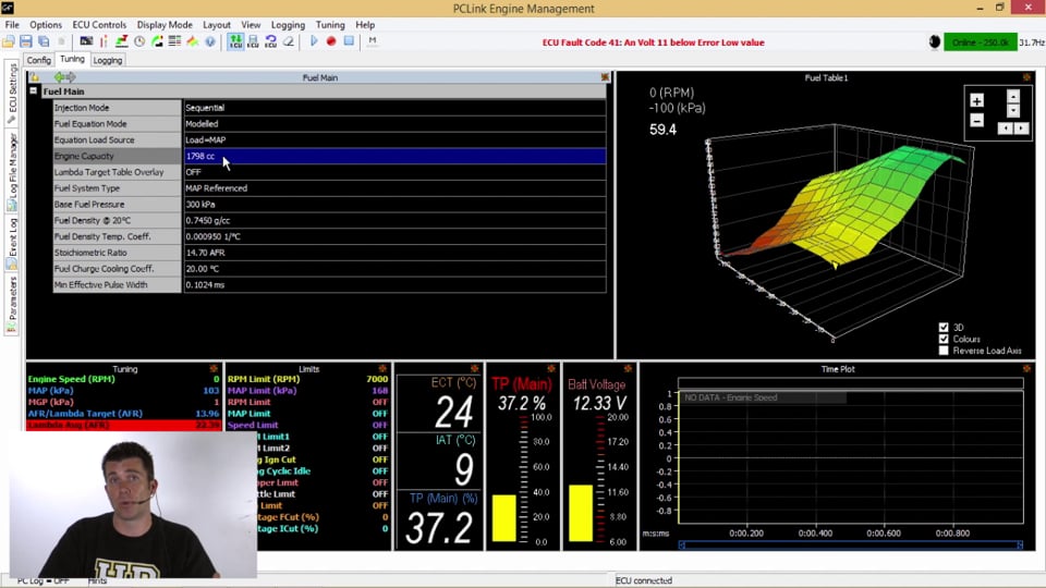
| 05:32 | So, if we start, we can go to the fuel setup table. |
| 05:37 | And if we go to the fuel main, you can see that now the fuel equation mode here, we've got selected as modelled. |
| 05:44 | Now, again, if you've watched all of this webinar, you decide this isn't for you, you're used to tuning on the traditional mode of the millisecond based fuel model, you can simply choose traditional and that will take you back to an ECU that responds exactly like what you were used to. |
| 06:01 | So, don't think that this is going to force your hand. |
| 06:04 | You're not required to use this modelled fuel equation if you don't want to. |
| 06:09 | You'll also see here we've got modelled multi-fuel. |
| 06:12 | Now, again, this isn't something we're going to have the opportunity to touch on here. |
| 06:18 | We're going to run another webinar on this, but again, one of the big changes with the 5.2.2 firmware has been the ability to do proper multi-fuel integration. |
| 06:29 | So, that allows the ECU to now properly tune across, for example, a blend of ethanol based fuels and properly account for the required change in fueling. |
| 06:42 | At the same time, you can use this modelled multi-fuel for two separate fuels, let's say C16 and normal pump fuel. |
| 06:51 | Again, we don't have the time to do justice to the multi-fuel equation right now. |
| 06:56 | We will do a separate webinar based solely on that. |
| 07:00 | Okay, so if we're using the modelled fuel, as you can see here, some of the parameters that we now need to address include, you can see here we've got our engine capacity. |
| 07:10 | So, the whole volumetric efficiency model is based around the ideal gas law, and for the ECU to be able to accurately calculate mass air flow into the engine, it's important that it understands what the engine capacity is. |
| 07:24 | So, we have to now enter our engine capacity, and it's important if you're doing this to take into account anything that's going to affect engine capacity. |
| 07:33 | So, if it's got a stroke, a crankshaft fitted, or it's been overboard, you're going to need to account for these changes when you enter that. |
| 07:42 | The other parameter that's really important here is our fuel system type, and you can see that we've got that set as map referenced here. |
| 07:50 | Now, if we open that up, you can see our options. |
| 07:52 | We've got none, so we've got no fuel pressure correction. |
| 07:55 | We've got map referenced, we've got returnless, and we've also got fuel pressure sensor, I should say. |
| 08:03 | So, this tells the ECU how the flow of fuel through the injectors is going to vary with changes in manifold pressure. |
| 08:12 | So, for example, we've got map referenced here, so what this means is that the fuel pressure will vary directly in relationship to our manifold pressure. |
| 08:21 | So, as the engine transfers up onto boost pressure, our manifold pressure will, sorry, our fuel pressure will increase, retaining a consistent differential fuel pressure across the injectors. |
| 08:32 | Our returnless system, which we're seeing quite often now in modern cars, means that we're running a fixed fuel pressure, so the flow through the injectors will vary as a function of manifold pressure. |
| 08:44 | And lastly here, fuel pressure sensor. |
| 08:46 | If we have got a fuel pressure sensor fitted, then the ECU can automatically compensate for changes in fuel pressure, and we're going to talk about that a little bit later. |
| 08:56 | So, for the moment, we've got a map referenced fuel pressure regulator on this car, and that's what we're going to use. |
| 09:03 | The next one we've got is our base fuel pressure, so this is the fuel pressure that we have the system set to. |
| 09:09 | And it works quite closely with some of the injector, one of the injector parameters we're going to look at shortly. |
| 09:15 | Again, if we're using a fuel pressure sensor, this is kind of a default value if the fuel pressure sensor goes into fault. |
| 09:24 | So, this needs to be set at the fuel pressure the system is running. |
| 09:28 | Some other parameters that we're probably, you're probably not going to be familiar with if you haven't tuned a VE based fuel model before, is some parameters to do with the fuel's properties. |
| 09:41 | So, we've got the density of the fuel, and this is measured at 20 degrees centigrade, as well as the fuel density temperature coefficient. |
| 09:49 | In plain English, what this means is, we're looking at the mass of the fuel, and also how the density of that fuel will fluctuate with changes in fuel temperature. |
| 10:01 | Now, if you don't have this sort of information, if you press F1 and bring up your help box, this is going to give you some typical values for some of the fuels that we're likely to see here. |
| 10:13 | So, petrol, ethanol, and methanol are listed in there. |
| 10:17 | And likewise, we've got those values there for the fuel density temperature coefficient. |
| 10:22 | So, don't be too scared of those. |
| 10:24 | Probably the majority of people are going to be tuning on either petrol or ethanol blends. |
| 10:30 | So, that's generally going to be covered reasonably easily there. |
| 10:33 | The other really important aspect here is our stoichiometric air fuel ratio. |
| 10:38 | So, that needs to be correctly set for the fuel that we're running. |
| 10:42 | We've also got fuel charge cooling coefficient. |
| 10:47 | Now, I'll explain this briefly. |
| 10:49 | We're actually going to look at how to program or how to tune that, because it's really important to the fuel model. |
| 10:54 | So, what this does is it basically accounts for the cooling effect of the fuel. |
| 11:01 | So, when we inject fuel into the engine, a certain proportion of it will be used to actually cool the intake charge. |
| 11:10 | And this is obviously after the intake air temperature sensor, so the intake air temperature sensor can't account for this cooling effect. |
| 11:17 | This cooling effect comes from the fuel's latent heat of evaporation. |
| 11:23 | So, when that fuel goes through a phase transfer from a liquid into a vapor, it actually absorbs heat out of the surrounding air. |
| 11:30 | So, this charge cooling coefficient accounts for that, how much heat the fuel will take out of the intake charge. |
| 11:39 | So, that's really important. |
| 11:41 | As I said, we'll look at how to tune that very shortly. |
| 11:43 | We've also got a minimum effective pulse width, which is the minimum pulse width that can be delivered to our injectors. |
| 11:50 | And this is going to come from our injector data. |
| 11:53 | And we're going to look at that next. |
| 11:55 | So, again, this is our fuel main table, our main menu, and there are some new parameters in there that you will need to correctly configure before you even start trying to start and run the engine. |
| 12:06 | It's very critical to get these correctly filled out. |
| 12:10 | Ok so, if we now look at our injector setup, again, there's a little bit more going on in the injector setup. |
| 12:18 | First of all, we've got our dead time table, which you're probably already familiar with. |
| 12:23 | This time we can set up that dead time table as either a two-dimensional or a three-dimensional table relative to our fuel pressure. |
| 12:31 | We're going to have a look at where all this data comes from shortly as well. |
| 12:36 | Then we've got our injector flow at the rated pressure for the injector. |
| 12:41 | So, again, this is going to come from our injector data. |
| 12:43 | Remember I said it's important, the ECU now needs to understand the capacity of the injectors or the flow, I should say, of the injectors so it can calculate what pulse width to apply to achieve the target air-fuel ratio. |
| 12:57 | Lastly, when we're talking about injector flow, the flow is always measured at a specific pressure, which is the rated fuel pressure, so we need to enter that for whatever particular pressure our injectors were flow tested at. |
| 13:11 | Now, we've also got a short pulse width at a table, which may be new to some of you, and at the moment you can see I've got this table filled out with zeros. |
| 13:20 | It doesn't really matter for the purposes of our demonstration, but what we're going to do is have a quick look at where this data comes from and why it's important. |
| 13:28 | So, first of all, if we look at this data here from Injector Dynamics, I've just happened to have this data supplied to me by Injector Dynamics, but a range of manufacturers or injector suppliers now will be able to give you the same data. |
| 13:44 | So, what we're looking at here is our injector flow in microliters per pulse relative to the injector pulse width in milliseconds. |
| 13:53 | Now, the first thing we can see, and this should probably be familiar to most of you, is we don't actually get any flow out of the injector at all until we reach about 1.1 or 1.2 milliseconds. |
| 14:05 | So, this is known as the dead time, also known as the injector offset or injector latency. |
| 14:10 | So, this is nothing new, we've been dealing with this in the Link and Vi-pec product for a long time now. |
| 14:16 | Ok now, when we look at the right-hand side of the graph here, this is what we're generally talking about when we're discussing injector rated flow. |
| 14:25 | So, the maximum amount of flow out of the injector at effectively a wide open flow, 100% injector duty cycle. |
| 14:33 | Now, if we, actually if we come back here, you can see that for the most part, we've got a reasonably linear graph here. |
| 14:41 | So, we could run a ruler through it, it's pretty much a straight line. |
| 14:44 | What that means is for the most part, if the ECU wants 50% injector flow, it would apply 50% injector pulse width. |
| 14:53 | Now, this is a really critical aspect to how the ECU calculates the required pulse width to supply though. |
| 15:00 | Now, that works for 3 quarters of the injector's operation, but if we have a look at this next graph here, which is the flow at very short pulse width. |
| 15:10 | So, this is what we're likely to see down at idle or just off idle. |
| 15:14 | You can see I've got a grey line here, which is a linear regression showing that theoretical straight line. |
| 15:20 | And once we get up past maybe 2.5 milliseconds, that seems to hold reasonably true. |
| 15:26 | Down here though, particularly at very low pulse widths, around that 1.5, 1.2 milliseconds, the flow deviates quite dramatically from that theoretical linear regression. |
| 15:38 | So, this is what we're talking about when we're talking about short pulse width adder. |
| 15:42 | There is a table which says, if I'm requesting 1.2 milliseconds of injector pulse width, this is how much to add to the output to the injector in order to get the theoretical flow that the ECU thinks it's going to get. |
| 15:57 | It's all about trying to get a much more accurate picture of the fuel requirements, and if the ECU knows this, it's going to be able to do a better job of getting accurate control of the injectors. |
| 16:12 | That's going to give us more accurate control over our air fuel ratio. |
| 16:16 | So, you might be thinking, where do these numbers come from? There's a couple of places. |
| 16:20 | So, again, I'm using injector dynamics data here. |
| 16:23 | This is the flow versus offset, so the injector dead time data if you like. |
| 16:33 | You can see we've got the injector dead time rated at different fuel pressures here. |
| 16:37 | So, if we want to use that 3D table, we can effectively copy this entire table out and put that into the ECU, and the dead time will be correctly compensated as the differential fuel pressure fluctuates. |
| 16:51 | Now, again, we've got our slope in cc's per minute, so this is our rated flow, and you can see, as I said, the rated flow is relative to a differential fuel pressure, so that's where those numbers come from. |
| 17:04 | I've also got here, if we download from injector dynamics, the data specific to something like HP tuners, you can see that all of the required data that we need to fill in that table is here. |
| 17:17 | We've got our minimum pulse width value, and we've got our short pulse width at a table. |
| 17:23 | So, this is where you're going to get that data. |
| 17:26 | If you want to do the job properly and make sure you're getting all of the benefits from that system, you do want to make sure you're using an injector that is properly characterized. |
| 17:37 | My understanding is that Electrons in Christchurch, New Zealand, are building an injector flow bench that will be able to generate this data. |
| 17:45 | So, I imagine in the course of time, you're going to be able to get this data directly from Electrons. |
| 17:51 | So, that's going to speed up your process and make life a little bit easier. |
| 17:56 | Okay, so let's drop back into the software now, and we'll go through the rest of the data. |
| 18:01 | So, we've got our injector dead time, which we've just talked about, that comes from that table. |
| 18:07 | So, once we've got all of that data set up, we can drop back into the main fuel table, and as I said, this table now represents our engine efficiency. |
| 18:19 | So, we're not directly talking about injector pulse widths inside this table. |
| 18:24 | It'd be reasonably normal for most performance engines to see the shape of this table, follow reasonably accurately the torque curve of the engine, and we're probably going to see numbers somewhere a little bit above 100% at peak torque. |
| 18:40 | The actual tuning of this table doesn't change too much if we double the number in the fuel table, just like the traditional millisecond based fuel table, we're going to be doubling the fuel delivery. |
| 18:54 | But the way we tune this table is also quite specific. |
| 18:57 | So, before we actually go and start tuning this table, the other aspect we need to look at is our AFR or lambda target table. |
| 19:06 | And what I'll do is I'll just change this so it is in units of lambda, which I personally prefer. |
| 19:14 | Ok so, remember what we're trying to do here is we're tuning the efficiency table, telling the ECU how much air is entering the engine. |
| 19:23 | So, we've already entered all of our injector data so the ECU knows exactly what pulse width to provide to provide a certain flow or mass of fuel. |
| 19:32 | So, before we start tuning though, the critical aspect is to correctly fill out this AFR lambda target table with our actual target lambda numbers. |
| 19:43 | So, this is the actual lambda numbers we want the engine to be running at. |
| 19:47 | Once we've done this, the process of tuning the engine is to simply go back to our fuel efficiency table and adjust the numbers in the efficiency table until our target lambda and our measured lambda match. |
| 20:00 | So, that's the process of tuning. |
| 20:01 | Once we've done that, the benefit, remember I said at the start, if we've done our job properly, we're using proper injector data and we've accurately calibrated the fuel table, what that means is if we then want to make a change to our target lambda, we can go back into the AFR lambda target table, just adjust our targets, and the engine will, the ECU will respond and make those changes to the tune automatically. |
| 20:27 | So, we won't need to go back on the dyno. |
| 20:30 | Now, this is a big change, particularly for a lot of ECUs. |
| 20:34 | Link and Vi-pec have already been doing this to a little bit, to a degree, with their open loop AFR table, which some of you may already have been using. |
| 20:44 | So, they'd already had the traditional millisecond based fuel table responding a little bit like a VE table anyway. |
| 20:53 | But for others who hadn't been using that feature, this will be quite new. |
| 20:57 | It's really critical to remember, this is the place where you need to start to correctly calibrate your target lambda before you go and do any tuning. |
| 21:06 | Ok so, what I'm going to do now is we'll just get our engine running. |
| 21:09 | I've got a Toyota 2ZZ engine on our engine dyno rig behind me in our dyno cell. |
| 21:15 | So, I'm just going to get that running and we'll look at a little bit of live tuning. |
| 21:22 | Ok so, we've got our engine running on our engine dyno behind us here, and at the moment we've just got it warming up. |
| 21:30 | So, I won't make any changes now. |
| 21:33 | One of the things I've already mentioned is that engine charge cooling coefficient. |
| 21:39 | And a lot of people are going to probably gloss over the importance of that, so I really want to make you aware of how critical that parameter is. |
| 21:49 | It can have a really big influence on your tuning, and it's something that you do need to address straight away before you actually spend a lot of time tuning the main fuel efficiency table. |
| 22:02 | If you don't do that, what's going to happen is when you request a change in target air fuel ratio, the ECU won't track that change correctly. |
| 22:12 | So, it's not going to be able to do its job correctly, and that's going to affect the accuracy of your tune. |
| 22:23 | What we'll do is we've just about got the engine up to temperature now, and I've just brought up the quick tune box here, which is just a really nice quick way for this webinar of showing both our measured and our target lambda numbers in the same place. |
| 22:37 | Now, what we'd traditionally be doing, as I've already sort of mentioned, is we would be highlighting our values in our fuel table there, and we can simply adjust the numbers in the fuel table until we actually match our target lambda to our measured lambda. |
| 23:00 | It's pretty straightforward. |
| 23:01 | Doesn't really change too much from how you would have tuned the traditional millisecond-based fuel model. |
| 23:08 | So, here's what we do need to do, though, before we get into any really involved tuning. |
| 23:15 | As I said, this is one of the first things you're going to want to do. |
| 23:19 | You're going to want to adjust the fuel charge cooling coefficient. |
| 23:24 | So, the way we do that is we request a change in lambda, and we see how accurately the target, the measured air-fuel ratio, measured lambda tracks that change. |
| 23:36 | So, you can see at the moment we've got the engine running with a measured lambda of 1.0, and again, our target lambda is 1.0. |
| 23:44 | So, if we go into the AFR target table here, and now I highlight all of the cells around where the engine's running, let's target now a value of 0.90. |
| 23:59 | You can see that the measured lambda didn't track correctly. |
| 24:02 | It's actually gone richer. |
| 24:04 | It's gone to 0.86. |
| 24:07 | So, what that means is our ability to tune the air-fuel ratio based solely off this table once the engine's tuned isn't going to work out correctly. |
| 24:15 | So, what we'll do is we'll go back into our fuel main, and I've purposely set this fuel charge cooling coefficient incorrectly at the moment just so I can show you how that works. |
| 24:28 | So, what we want to do, if the, when we request that change in lambda, so I've gone from lambda one to 0.90, if the requested change actually results in a measured air-fuel ratio that's richer, what we want to do is reduce this charge cooling coefficient. |
| 24:46 | So, what I'm going to do is reduce that to 10 degrees, and what we're going to do now is just go over the exact same process again. |
| 24:55 | So, we're going to change our target back to lambda one, which you can see we've tracked correctly. |
| 25:03 | Let's change that back to our target of 0.9. |
| 25:07 | Now, you can see we're much, much closer. |
| 25:08 | We've gone to 0.89 now instead of 0.86, which we were at. |
| 25:13 | We're still slightly rich though, so what we can do is go back to our fuel charge cooling coefficient. |
| 25:20 | Let's set that to eight degrees. |
| 25:22 | Now, you can see now we're actually right on our target. |
| 25:27 | We'll go back and request our original target of lambda one. |
| 25:31 | Now, remembering when you are changing this charge cooling coefficient, you may find that when you go back to your original target lambda, that it requires the main fuel efficiency table to be adjusted slightly as well. |
| 25:47 | But you can see now we're right on our target of lambda 1.0, and if we go back to 0.9, you can see that it's automatically changed right to 0.9. |
| 25:59 | If we go to 0.95, somewhere in the middle, you can see again it's tracking correctly. |
| 26:05 | So, this is one of the first things you need to do. |
| 26:08 | If you try and do this after you've already tuned the fuel efficiency table, what that's going to mean is that you're going to have to go back and readdress some of that fuel efficiency table. |
| 26:18 | So, you do need to do this quite early on. |
| 26:21 | Now, I recommend, despite the fact that the ECU is now properly characterized for that short pulse width at in the injectors, I still recommend doing this at an area in the tuning where we're outside of that low short pulse width area of operation of the injectors. |
| 26:42 | So, you can see I've chosen 3000 RPM, and we've got 20% throttle as a good place to be to make sure that we're in an area of linear flow, and that's going to make sure that the numbers that we're putting into that table are correct. |
| 26:58 | So, once we've done that, then we can jump back into our fuel table and tune the engine exactly the same way that we always would have. |
| 27:06 | It is important though when you're doing this to make sure that you're always referencing the target lambda number to your measured lambda number. |
| 27:18 | So, rather than just making up the target lambda number in your head or watching where you are in the fuel table and deciding in your head what particular air fuel ratio you want to tune for, you do want to make sure that you've already done that and correctly filled out that air fuel ratio target table, and make sure that your measured lambda at all of the areas in the fuel table are correctly matching that target lambda table. |
| 27:43 | And that's as simple as it is really. |
| 27:46 | It does require that little bit of extra work, particularly in your setup, but if you do that, you are going to get those benefits of being able to change fuel pressure, being able to even completely change the type of fuel regulator system on the car. |
| 28:02 | So, you could go from a returnless system to a manifold pressure reference fuel pressure regulator, and you don't even need to go back on the dyno, just enter that new data inside the ECU, and the ECU will be able to cope with that automatically and make the required changes to the fueling. |
| 28:20 | So, again, just to reiterate, what we're going to do when we're tuning on this new modelled fuel system is we need to start in our fuel main table, and it's simply a process of working down through this table, through this table of data, and correctly filling out, first of all, our engine capacity, then the type of fuel system that we're using, so how the fuel pressure regulator works, what our base fuel pressure is set to, then those characteristics for our fuel density and our fuel density temperature coefficient, our stoichiometric air fuel ratio, the fuel charge cooling coefficient that we've just looked at, and also then we've got our minimum injector pulse width. |
| 29:06 | We can then, once we've set up that, we can then go into our injector setup, make sure that our dead time table is correctly characterised, that we've got our correct injector flow at our rated pressure, our correct injector rated pressure, and we've got our short pulse width and dead time data correctly entered. |
| 29:26 | From there, the next process is to go into our AFR lambda target table, correctly enter into that lambda target table your actual desired air fuel ratios, or lambda targets at every point in the table. |
| 29:41 | Once we've got all of that set up, we can then start the engine and get it running. |
| 29:45 | Now, remember, the first thing we want to do once we've got the engine sort of settled down and running correctly is go and address that charge cooling coefficient, set that up correctly so that the ECU can properly follow our changes, our desired changes in target lambda. |
| 30:04 | And once that's all done, then we can fill in the main efficiency table, tune the fuel table exactly as we would have done with our traditional fuel model. |
| 30:14 | Now, once we've done all of that, then we can get those benefits from the volumetric efficiency or model fuel equation. |
| 30:23 | Now, again, as I said at the start, if all of this is looking like it's a bit too much work or you don't think you can get your head around it, it is very, very quick and easy to do in reality once you've done it once or twice. |
| 30:34 | But if this isn't for you, you still have the option of going back into that fuel main menu and selecting traditional, and that will have the ECU operate exactly as it always has with no changes, so don't be scared. |
| 30:50 | It's not a change that you have to use if you don't want to. |
| 30:54 | OK, so before we go, I will just touch on the dual fuel modelled equation. |
| 31:02 | Now, I said we don't have time to really get into this in too much detail. |
| 31:07 | We will be doing another separate webinar specifically on this. |
| 31:12 | But one of the questions we've had a lot, and I know that Electrons have also had a lot, is when we move to the dual fuel modelled equation, we now have two volumetric efficiency tables, and I know a lot of people don't really understand why that's the case. |
| 31:27 | Particularly, when you look at it on the basis of it's just the fuel that we've changed, the volumetric efficiency table is defining airflow into the engine, so hence, how is it possible that the volumetric efficiency of the engine will alter? Now, there's two reasons behind that. |
| 31:43 | One is, despite the fact we are talking about fuel, there is actually a real change in volumetric efficiency happening. |
| 31:51 | And the reason for that is, particularly when we look at a change such as pump fuel to E85 or 100% ethanol, when we make that change, the cooling properties of that ethanol fuel will affect that charge cooling coefficient. |
| 32:05 | And what it's doing is it's cooling the intake charge a lot better than petrol can. |
| 32:11 | It's got a much higher latent heat of evaporation. |
| 32:13 | And when it does that, what it does is it pulls a lot more heat out of the air, makes the intake charge a lot denser, and what that does is it allows more air to be packed into the engine. |
| 32:23 | Now,, that will result in a small change in volumetric efficiency. |
| 32:27 | That's one of the reasons why direct injection gives an improvement in the engine's volumetric efficiency because all of the fuel being injected, or the majority of the fuel being injected in a DI engine is being used for charge cooling as opposed to taking heat out of the port walls, the cylinder head, and the intake valves, for example. |
| 32:48 | So, that's one reason. |
| 32:49 | The other reason is, understand that the fuel equation being used here is attempting to model the behavior of the engine across just about any engine you could feasibly put a Link or a Vipec ECU on. |
| 33:04 | So, it's impossible to accurately measure all of those parameters and properly model every single potential change. |
| 33:13 | Otherwise, as tuners, we'd simply be there for ever entering list after list of parameters that we probably don't even have the data for anyway. |
| 33:22 | So, the system has been dulled down to a point where it works effectively, it's accurate, but it's also just as importantly easy to tune for the tuner. |
| 33:32 | That's why the second VE table is there to make a, I guess you'd call it a fudge factor if there are errors in that fuel model as we change fuels. |
| 33:43 | So, as I said, we will look at this in detail in a future webinar. |
| 33:47 | One more parameter I just realized I haven't discussed though is the charge cooling estimate table, which is another change that's been made with the move to the modeled fuel table. |
| 33:59 | Now, if we look at the laptop software again, you'll be familiar with seeing the intake air temperature correction table. |
| 34:06 | This is a table that's been available for a long time in the Link and Vi-pec software. |
| 34:11 | And what this is meant to do is account for changes in the air density as the intake charge temperature changes. |
| 34:20 | Traditionally, this has been dealt with horribly by tuners. |
| 34:23 | Most tuners don't understand how it works or what numbers to enter in here. |
| 34:28 | In broad terms, this is just being dealt with, this is just a result of the ideal gas law. |
| 34:35 | And if we heat up a gas, it becomes less dense. |
| 34:39 | So, in the case of our intake charge, as we heat it up, it contains less oxygen, so we generally need less fuel to achieve our same air fuel ratio target. |
| 34:49 | Likewise, if we cool the intake charge down, if it's colder, it becomes more dense, it contains more oxygen, and we need more fuel. |
| 34:57 | In rough terms, the amount of changes is around about two to two and a half percent per 10 degree centigrade change in intake temperature. |
| 35:06 | Now, with a volumetric efficiency based fuel model, that change in intake temperature is accounted for directly in the fuel equation, so we don't strictly need to change that. |
| 35:18 | That's why you can see that this table currently is filled out with zeros. |
| 35:22 | What we do have though is our charge temperature approximation table, which popped up in a recent firmware update. |
| 35:31 | Now, what this table is doing, again, I know a lot of people are struggling with how it works. |
| 35:36 | What this table is doing is providing a weighting to where the ECU will take its intake air temperature value from. |
| 35:47 | So, obviously we have an intake air temperature sensor that may be fitted in the intake pipe pre-throttle body, or maybe it's fitted into the intake manifold itself. |
| 35:57 | So, that's measuring the temperature of the air as it goes past that sensor. |
| 36:01 | Particularly if it's mounted, let's say, in the air box or the intake pipe, there's a lot of things happening to that air once it's gone past the sensor, which we then can't properly account for. |
| 36:12 | What we really want to know for that volumetric efficiency based fuel model is the temperature of the air as it goes past the intake valve, and we just simply don't have the ability to accurately measure that. |
| 36:23 | So, this table here gives an approximation of that charge temperature, the temperature as the air goes past the valve, based on both the engine coolant temperature and the intake air temperature. |
| 36:34 | So, you can see in here we've got numbers ranging from, at the moment, 90 down to zero. |
| 36:39 | And this weights how the ECU will determine the charge temperature. |
| 36:44 | If we had a number of 100% in this table, it's going to use the engine coolant temperature as the charge temperature estimate. |
| 36:53 | If we have at this point here a number of zero, what it's going to do is solely base the charge temperature off intake air temperature. |
| 37:00 | Now, how that works is that at low load and low airflow, particularly, let's say, idle, the airflow or air speed is quite low. |
| 37:08 | So, as it goes past the intake air temperature sensor, it's going to actually still have a lot of time available to draw heat out of the intake manifold, the port walls, and maybe the intake valve as it journeys into the engine. |
| 37:21 | So, the air is quite likely going to heat up dramatically as it makes its way into the engine. |
| 37:27 | So, that means that, particularly at low load, low airflow, the intake air temperature sensor solely is not really a good indicator of true intake charge temperature. |
| 37:37 | So, in these cases, particularly down here, you can see we're using a number of 90 and maybe 70%. |
| 37:42 | So, it's focusing or weighting its charge temperature estimate towards the engine coolant temperature because the engine coolant temperature's a good indicator of what the cylinder head temperature and port wall temperature is going to be. |
| 37:57 | On the other end of the scale, though, at very high loads and high airflow, there isn't a lot of time available for that intake air temperature to rise. |
| 38:05 | So, the intake air temperature sensor is going to be a better indicator of true intake charge temperature. |
| 38:11 | So, that's why we can use a number of zero down at these points. |
| 38:15 | Now, if you don't have any idea what numbers you should be putting into this table, if you press one, you've got a reasonably good starting point in the help file there of some values that you can put into that table. |
| 38:29 | Now, you saw it, we still have our IAT fuel trim, the conventional table, available there. |
| 38:35 | Now, again, because this fuel model is meant to work across every engine, every combination of intake manifold, perhaps aluminum, perhaps plastic, it's very difficult for this fuel model to perfectly fit absolutely every engine that people out there may be fitting a Vi-pec or a Link G4 Plus ECU to. |
| 38:55 | So, if we find that that fuel model, that charge temperature estimate model, isn't quite working correctly in some instances, we can use this IAT fuel trim table to adjust those results and get the air fuel ratio tracking our desired targets correctly across a wide range of operating temperatures. |
| 39:16 | But it's important to make sure that you start with this table filled out with zeros, otherwise you're effectively going to be doubling up the response of the ECU's fuel model to changes in intake air temperature. |
| 39:30 | Alright, hopefully that's given you some insight into these new features in the 5.2.2 software and given you some more insight into the correct workflow of how you should be approaching tuning this new fuel equation on the G4 Plus and I88 series of ECUs. |
| 39:49 | For those of you who haven't been involved with the High Performance Academy already, if you do have further questions, feel free to ask those on either Vi-pec or Link's online forums. |
| 40:02 | The High Performance Academy, we're an organization set up focusing on providing high quality online EFI tuning training. |
| 40:11 | So, if you are interested in getting involved and learning a little bit more about tuning, we do have courses available to do that and you can find us at www.learntotune.com. |
| 40:23 | Thanks for joining us and we'll see you all next time. |


