Grounding problems are without a doubt the most common cause of electrical gremlins in the automotive performance world. This is because on the surface it seems like such an easy thing, just ground everything to the chassis of the vehicle, the more grounds you run the better it'll be, right? Not quite. Once you delve in, and start analyzing the grounding requirements of an EFI system, it can get rather complex. It's important to get it right though, or you'll end up chasing those gremlins in circles till you're frustrated enough to part with your money and pay someone else to chase them for you.
In this article: Misfiring | Assumed Problem | Actual Problem | Determining the Cause | Effecting the Repair | Proving the fix
We recently came across a car with a really interesting grounding issue. It was a perfect opportunity to document the diagnosis process we went through so you can follow along with us. The subject matter here is pretty dry, but we'll try to spice it up where we can, and there is some really great learning ahead if you stick with us.
Misfiring
The car in question is a 1994 S14 Nissan Silvia K's, with the factory fitted SR20DET engine still in place. The engine has some mild bolt on modifications, with a plug in Link G4+ ECU. It came to us to be tuned for the modifications, and initially the process was going very smoothly. The low to mid RPM steady state tuning was a breeze, as the modifications undertaken are a pretty well trodden path. While performing the full power tuning however, the engine would refuse to rev above 6400 RPM, it would instead buck and misfire. Pops and bangs can be great when they're asked for, but if you get them when you're not expecting it, you have a problem. Looking at the datalogs, they showed a very erratic engine speed signal as the engine approached the 6400 RPM point. Arguably, the engine speed signal is the most important input to the ECU; if it can't keep track of the engine speed it can't fire the fuel injectors or ignition coils at the right time and hence it can't run the engine correctly.
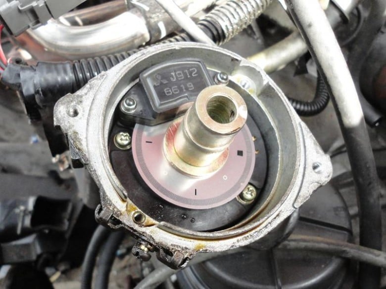
Photo credit: www.datsun1200.com
Assumed problem
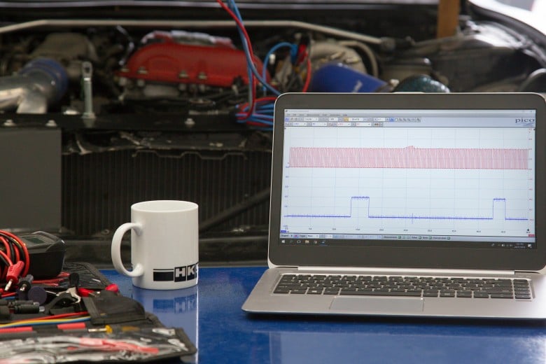
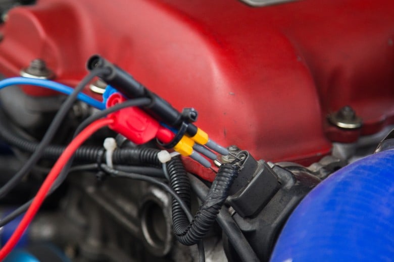
We're guilty of the cardinal sin of automotive diagnosis here; we made an assumption. It's reasonably well known that the triggering pattern Nissan chose to use on their engines of this era can give issues with aftermarket ECU's at high engine speeds. Without getting into the nitty-gritty of the operation of these Nissan trigger sensors, they output a very high-frequency signal, which only gets higher as the engine speed increases. It's common practice when tuning an aftermarket ECU fitted to a Nissan engine of this era to modify the engine speed sensor to output a lower frequency signal which seems to interface better with aftermarket ECUs. The exact mechanics behind the nature of the problems encountered when using the original Nissan signal pattern are often up for discussion. As we blindly assumed it was this same issue we were having, we thought it a great opportunity to get some detailed data and analyze what was really going on. We hooked up an oscilloscope to the trigger signals so we could get a good look at them, but even with the engine at idle, the alarm bells started ringing.
Actual Problem
Now, don't get scared off by the oscilloscope traces, the squiggly lines can be a bit confusing if you're not familiar with them, but they tell a great story and if you stick with us we'll break it down. A quick explanation of oscilloscopes? They're just volt-meters. They show us an image of what the voltage level is right now, but also how it has changed over time. The bit that takes some experience is interpreting this picture to figure out what it's trying to tell you.
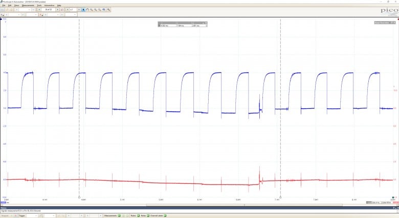
The signals we've scoped here are the high-frequency engine speed signal (Trace A, Blue), and the low-frequency engine phase signal (Trace B, Red). What we're ideally looking for in a trace of a signal like this is clean regularity and sharp edges and the traces here are not those things. There are a few terms that describe them, however; 'Messed Up', 'Ugly', and 'Trouble' are just a few. In particular what set the alarm bells ringing is where the lower bounds of the signals fall below zero to negative values, and as they snap back up there is a big pulse of high-frequency noise.
There are two main issues here. First, we'll look at the lower bounds of the signal falling below zero. When you're measuring a voltage, you're measuring the difference in electrical potential between two points. It's the case 99% of the time that we choose one of these points to be the ground reference of the vehicle, essentially the battery negative. The scope trace then shows us the difference between ground and our signal. Here we see the lower bound of our signal dipping into negative values... While there are situations where you expect to see negative voltage levels in automotive electronics, the output of a Nissan timing sensor is not one of them; Its a digital switching device and the voltage signal it outputs should always be equal to, or above the ground reference of the vehicle.
Issue number two is a large spike of high-frequency noise injected into the signal as the lower bound of the signals snap back up to zero. The spike has an amplitude of almost half our overall signal amplitude which is definitely significant. More worrying, however, is the width of the noise as it’s visible in the signal for a quite a long time. If the injected noise amplitude gets high enough and long enough, the ECU will no longer be able to distinguish it from the actual sensor signal, and it will lose track of the engine speed and phase. This is a very bad thing.
Determining the Cause
Well, we've got a pretty good handle on what the problem is, but unfortunately, that's not even half the battle. We need to determine what is actually causing the problem, so we can perform a repair we are confident of. Once again, experience does play a role in determining what could be causing us to see scope traces like this but follow along with the thought process.
When you see odd voltage offsets like this, it's a pretty sure sign you've got electrical currents flowing where they shouldn't be. The wires in an EFI wiring harness are sized for the level of current expected to pass through them. Wires are really just low-value resistors, they offer very little resistance to the flow of current, but 'very little' is not the same as 'none'. When a current flows through a wire, it creates a voltage offset at either end of the wire. If the current flowing through the wire is too large for the size of the wire, this voltage offset becomes large, like what we're observing here.
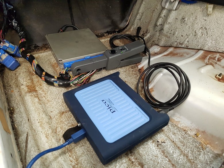
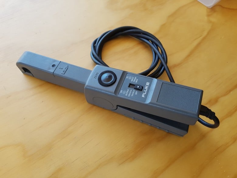
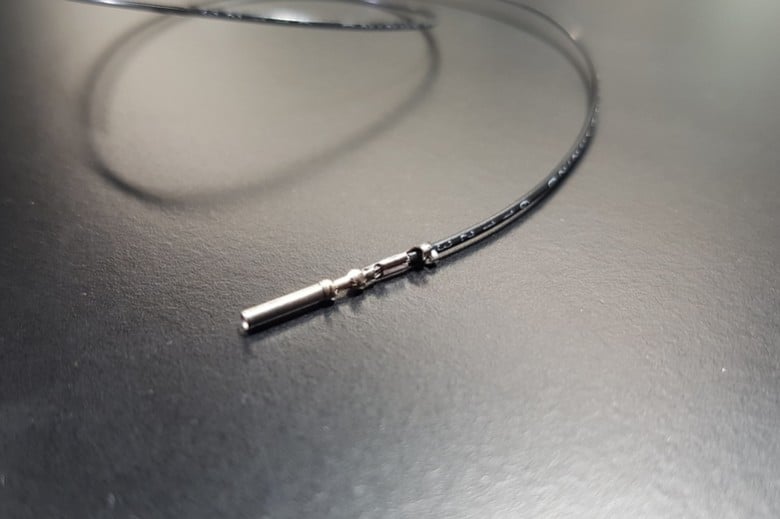
So far we've used our oscilloscope to measure voltages directly, but we're now pretty sure what we actually need to be hunting for are stray currents. The weapon of choice for this hunt is known as a current clamp. It's in a class of instruments we term 'transducers', it measures the current flowing in a wire (both amplitude and direction), then converts this measurement to a voltage signal we can see and store on our oscilloscope. This tool can be a real eye opener, as we can get pictures of the current flowing in every individual wire connected to the ECU, which is exactly what we did, the highlight of which is shown below.
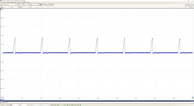
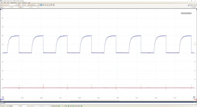
This picture shows the amplitude and direction of the current flowing in the wire connected to Pin 107 of our Link G4+ Plug-In ECU. This pin is one of the ECU grounds, and the size of wire is pretty large in the scheme of things - 18AWG. We could expect to see a reasonable level of current to be flowing through this wire, which is exactly what we're observing. The scale of the conversion the current clamp performs is 100mV per 1A of current, so we've got almost 2A of current flowing through our wire at regular intervals. The periodic nature of our signal is also pretty normal. Internal combustion engines are periodic things, they are based around a repeating cycle. So this all seems pretty normal, right? Well, after double (triple, and quadruple) checking the direction the current clamp was facing, we noticed that this repeating current was flowing into the ECU. This makes no sense, as ECU's operate as low side switches, they pass the current they receive from things like fuel injectors and ignition coils out of their ground wires back to the battery negative. We should categorically not be seeing a current flowing into the ground wires of our ECU.
We measured this current with the engine idling at a speed of 1000 RPM. The period of the signal is approximately 30ms, and if we work the math backwards, this equates to a pulse of current every 180 degrees of crankshaft rotation. This is a key piece of information, as for a four cylinder, four stroke engine, this is the same timing as combustion events. For our direct spark, sequentially injected SR20DET engine, the main actuators fitted to the engine being fired by the ECU every combustion event are the fuel injectors, and ignition coils. The level of current we’re seeing here eliminates the fuel injectors as the culprit, so we can narrow down the source of our stray current to the ignition coils, but why is it flowing into the ground wires of our ECU?
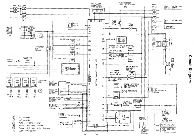
We're a little lucky in this situation that an S14 Silvia is a very popular car, so reliable OEM documentation on the layout of the EFI wiring harness is easy to obtain. Looking through this documentation we can see that the current output wire from the power transistor unit (commonly called an ignition module, or igniter) is crimped to the wires that connect to pins 10, 20, 107, 108, and 115 of our ECU. There is another single wire exiting this crimp join, which then heads to the main EFI system grounding point on the intake manifold. The intention is that the ignition coil primary winding current exits the power transistor unit, it flows to this grounding point unimpeded. However, if the section of wire after the crimp connecting everything together was damaged in some way, the current might find another path, one we don’t want it to take, like through our ECU.
The next logical step would be to use a multimeter to measure the resistance between this crimp point the the EFI grounding point, right? Yes and no. It’s worth doing as a matter of course, but what you're actually measuring is the resistance of the combination of all possible paths the current might take between these two points. Looking at our OEM wiring information again, we can eliminate any alternative paths if we unplug our ECU, isolating only the path we want to measure. What we observe, however, is that this results in no change, we still get a reading of almost no resistance between the splice point and system ground. If we take these results at face value we determine that the coil current exiting the power transistor module has a free, clear and unobstructed path directly to the EFI system ground, but is choosing to flow through the ECU instead. Confusing.
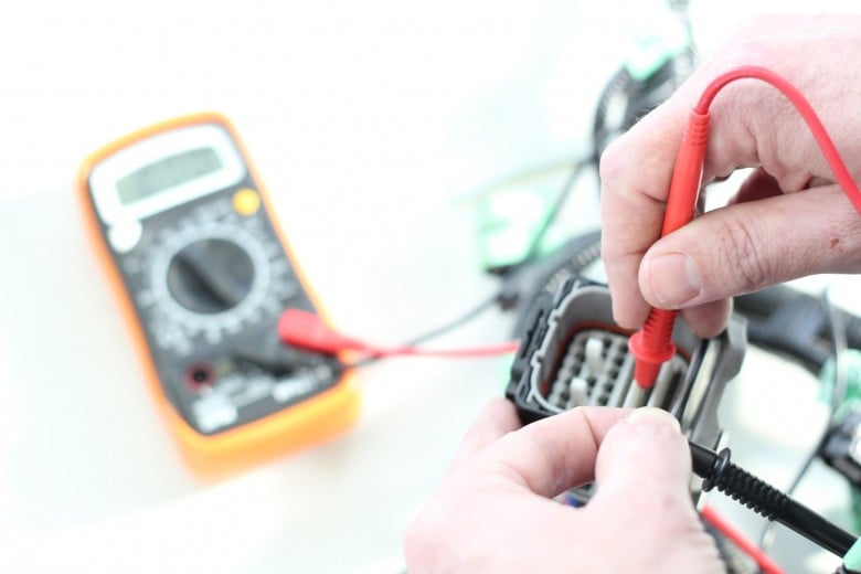
What our multimeter test fails to take into account is load. The way a multimeter determines resistance is to pass a very small current along the path between the two probes, measure the voltage offset this creates, and from this calculate the resistance the current is seeing. This very small current doesn’t put any part of the measured path under a significant load, and if the problem only occurs when that load is in place, a multimeter is not going to help you see it. To be completely 100% accurate, a multimeter with much, much higher resolution would let you find the problem with the system unloaded, but sensitive enough gear is many thousands of dollars and not commonly available on the workshop floor!
So, we’ve narrowed down our search area to the length of wire connecting this splice point to the main EFI system ground, we're looking for a dodgy connection at either end or some sort of physical damage to the wire along its length. At this point it's very likely we're going to end up removing the EFI wiring harness from the vehicle to repair it, however, that's a reasonable time investment, and we'd like to be really sure our plan of action is going to solve the problem. The possibility of a dodgy connection to the EFI system grounding point is easily tested and ruled out, as it is accessible with the wiring harness in place. Getting to the splice point, or examining the length of the wire itself is much trickier, and will definitely require removing the wiring harness from the vehicle.
However, we can prove that a more in-depth investigation will be successful before we undertake this step. We can de-pin the ground connection from the power transistor module connector, and re-pin it with a temporary wire external to the harness that connects directly to the EFI system ground point. With our temporary ground in place, we found that this did provide the low resistance path needed to persuade our coil primary winding current to stay away from our ECU. Excellent.
Effecting the Repair
Now we know roughly what we're looking for, and pretty specifically where we're expecting to find it, we can dig in, commit, and remove the EFI wiring harness from the vehicle. Luckily, Nissan made this part of their system pretty modular, and there is only one connection point between the EFI system and the rest of the vehicle electrics, making removing the harness as a complete unit comparatively easy. With the harness on the bench, we can start removing the coverings.
As typical for a car of this age, the harness covering is in very poor condition and time-consuming to peel back. However, the combination of doing our homework, and undertaking some logical tests has given us a specific area to look so we don't have to completely dismantle everything.
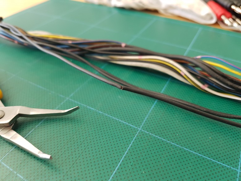
We love it when a plan comes together. Or in this case, a hypothesis is proven. Right beneath a portion of the wiring harness that runs along the firewall was a partial break in the wire we identified as being the likely culprit. All but one strand of copper had been severed, leaving just enough to confuse our multimeter test, but not enough for our coil current to pass unimpeded to ground. At this location the harness showed some signs of being crushed, most likely while the engine was being removed or installed at some stage.
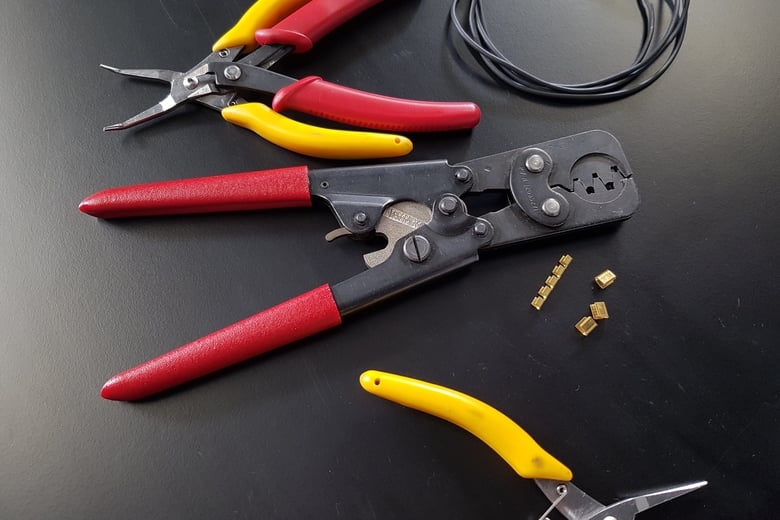
The repair could be as simple as cutting out the damaged section of wire, crimping the two ends back together and heatshrinking to seal. But if we've got the harness opened up on the bench, why not make an improvement while we're here? If you've stuck with this article to this point, you deserve to come away with the golden nugget of grounding system knowledge, and that is the idea of 'Star Point Earthing'. Simply, this technique ensures that our ground currents are restricted to only one path. If something goes wrong with that path, it can’t find an alternative.
To improve this harness for its current application, along with repairing the damaged section of wire, we removed the original wire connecting the power transistor module to the splice point, and replaced it with the external wire we used to prove our hypothesis, except this time we integrated it into the harness, making it a permanent solution. If this wire was to get damaged in the same point again, there would no longer be an alternative path for the coil current to take, as the power transistor ground terminal is no longer connected to the splice point. Sure, the engine would most likely not run, but the diagnosis would be much simpler! What we're really accomplishing here is to force a failure mode we're in control of. If there is a failure, the system will shut down, instead of continuing to operate in an undefined fashion.
Proving the Fix
With the repaired harness re-wrapped and reinstalled, the scope picture of the triggering signals now looks much cleaner. The real proof is that the engine now revs cleanly out to 7500 RPM with a solid engine speed trace the entire way, making completing the tuning job possible.
Grounding problems like this are all too common and are often fixed by the trial and error method. Parts of the system are replaced in turn, each time hoping the new part will fix the problem, in turn proving that the replaced part was at fault. While that approach generally works in the end, it can be very time consuming and expensive for the customer. They may end up paying for parts to be replaced that were actually in fine working order. The ‘Root Cause Analysis’ we performed here let us narrow in on the problem with each step as we gained new information until the definitive cause was identified. With the trial and error approach, you would only ever have a vague idea of the part of the system that was at fault. The satisfaction of pinpointing the issue, proving your hypothesis, and knowing your repair will be reliable is priceless.
Want to learn more? Start here with our Wiring Fundamentals course.