Sale ends todayGet 30% off any course (excluding packages)
Ends in --- --- ---
Hello,
I have a project that I'm considering using DBW Throttle to assist in controlling manifold pressure because external waste gate flow is insufficient. Before getting in the details of how I propose to do this, I would like to give some background to put this in context.
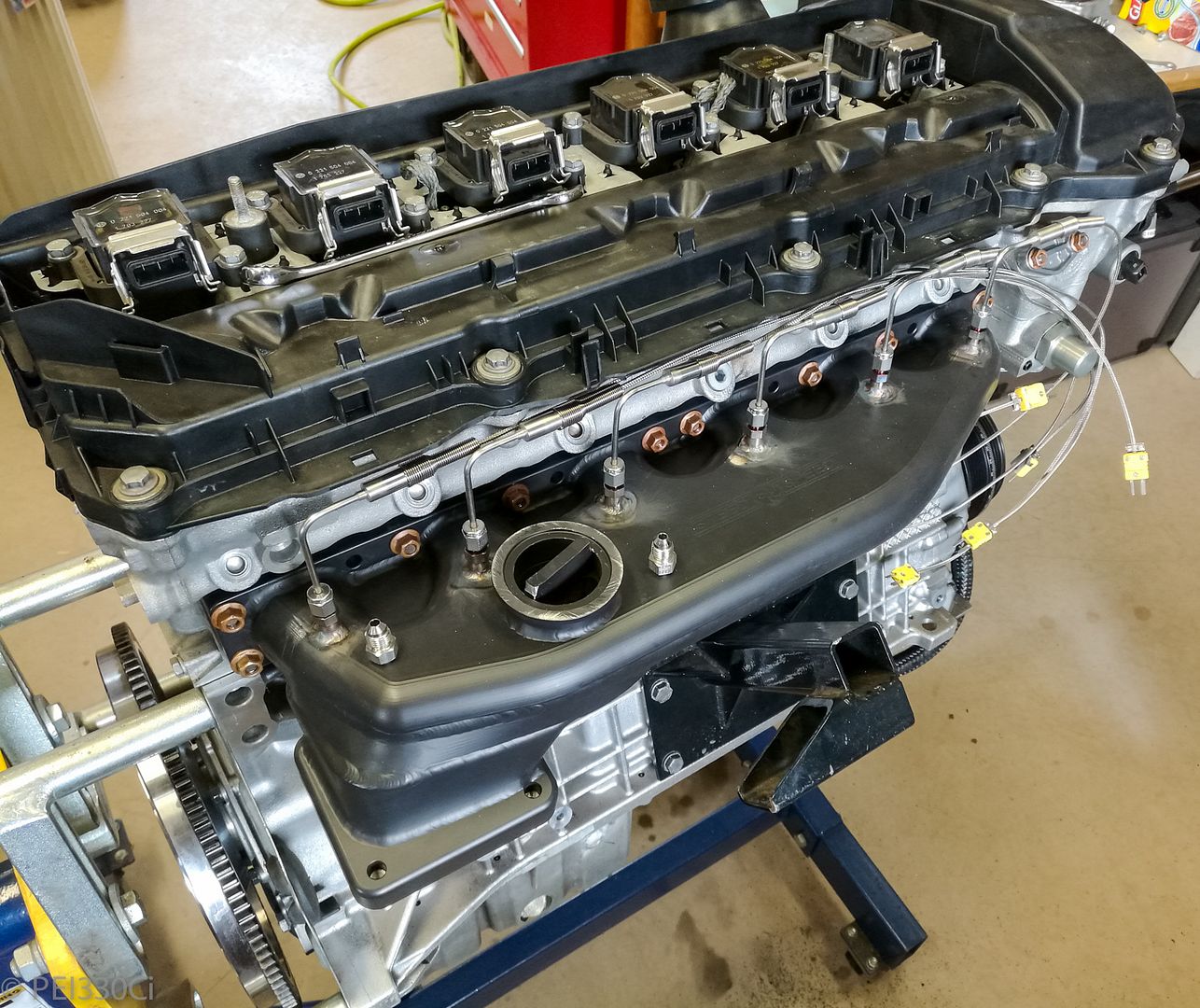
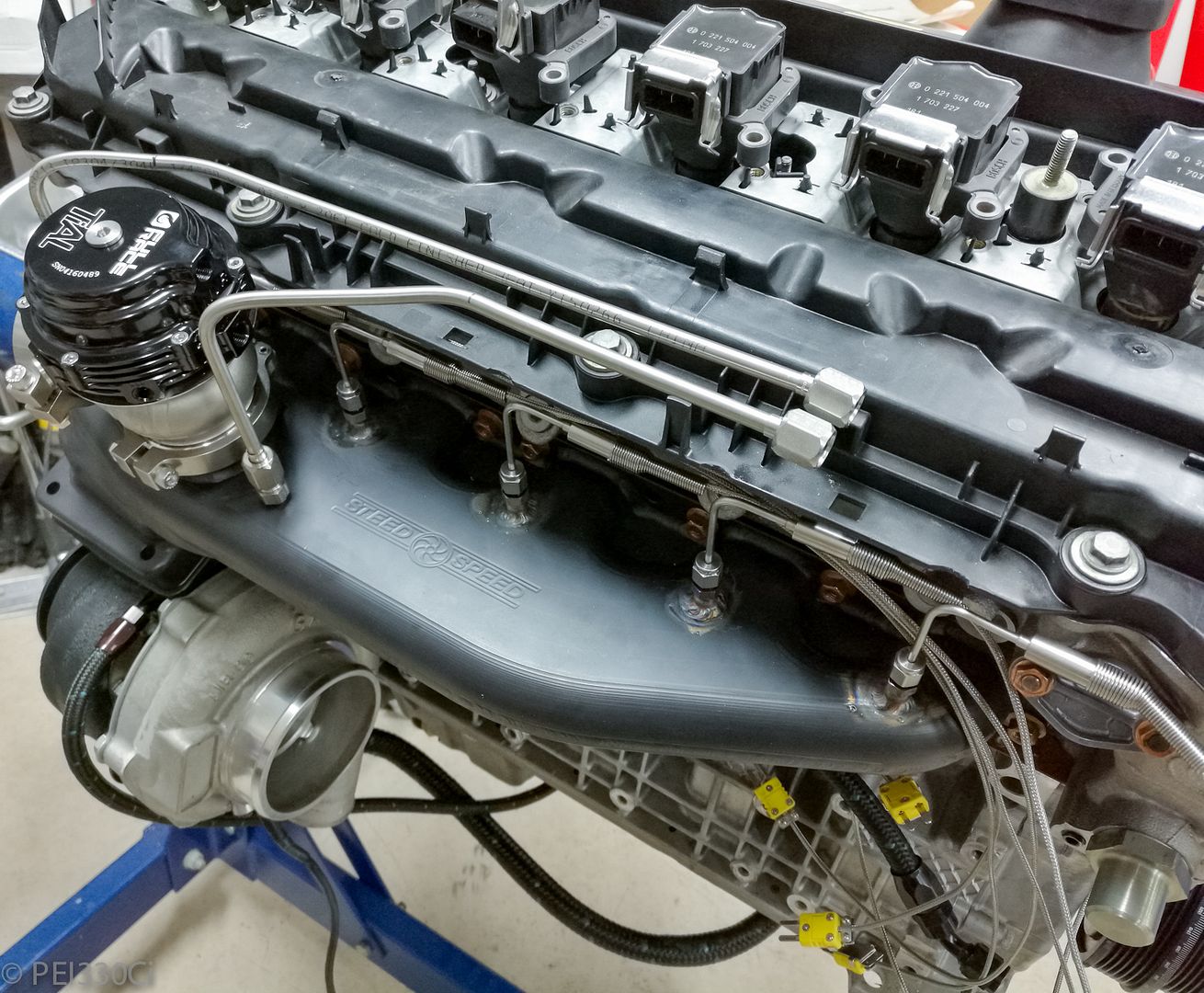
I have a twin scroll turbo manifold on a 3.0L engine that uses a single 44mm re-circulated WG for boost control:
Initially, I ran a GTX3076R turbo with a T4 1.06 A/R twin scroll housing. With this combination, I confirmed control with WG spring pressure alone down to 5 PSI of manifold pressure. I then used a 10 psi spring, and boost control on a Motec M1 to control manifold pressure up to 19 PSI when drag racing. Based on data logged, I was running the compressor well off of the map, and also had high exhaust back pressure. (42 PSI EBP @ 19 PSI manifold pressure)
Switching to a GTX4088R turbo with a T4 1.06 A/R twin scroll housing dramatically reduced exhaust back pressure, but I was no longer able to control boost at higher RPMs with the single 44mm recirculated WG. (Yes, the manifold design is not optimal for WG flow, but limited space was significant factor in it's design.) This left me evaluating quite a few options:
1.) Run an open dump pipe for the single WG
2.) Increase exhaust back-pressure (Post turbo) to manipulate the pressure bias to the WG.
3.) Increase the size of the single re-circulated waste gate. (60mm)
4.) Run 2 smaller Waste Gates on the manifold. (One for each bank)
5.) Run a single waste gate on the turbine housing
6.) Run two waste gates on the turbine housing
7.) Use DBW Throttle control to limit manifold pressure
Another user of this exhaust manifold on a 3.0L engine running a "big turbo" helped with Option #1; they removed the WG entirely and still experienced boost creep.
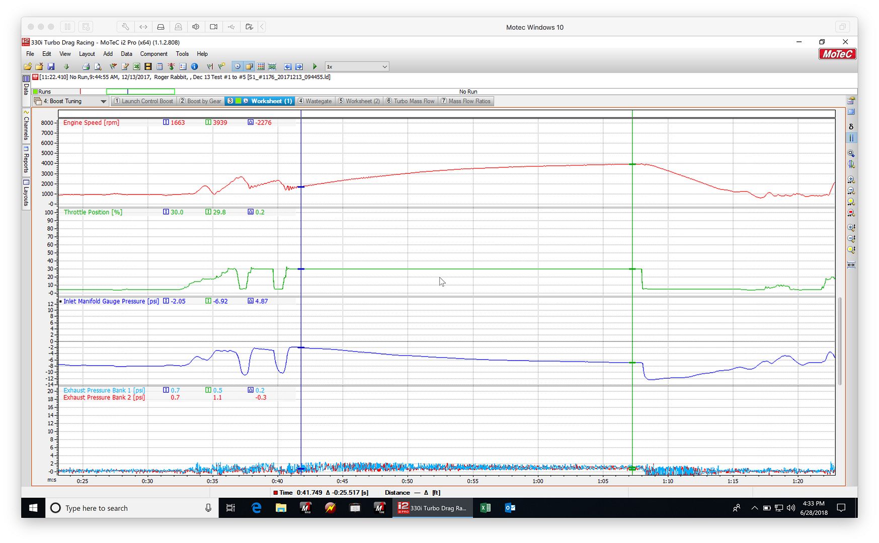
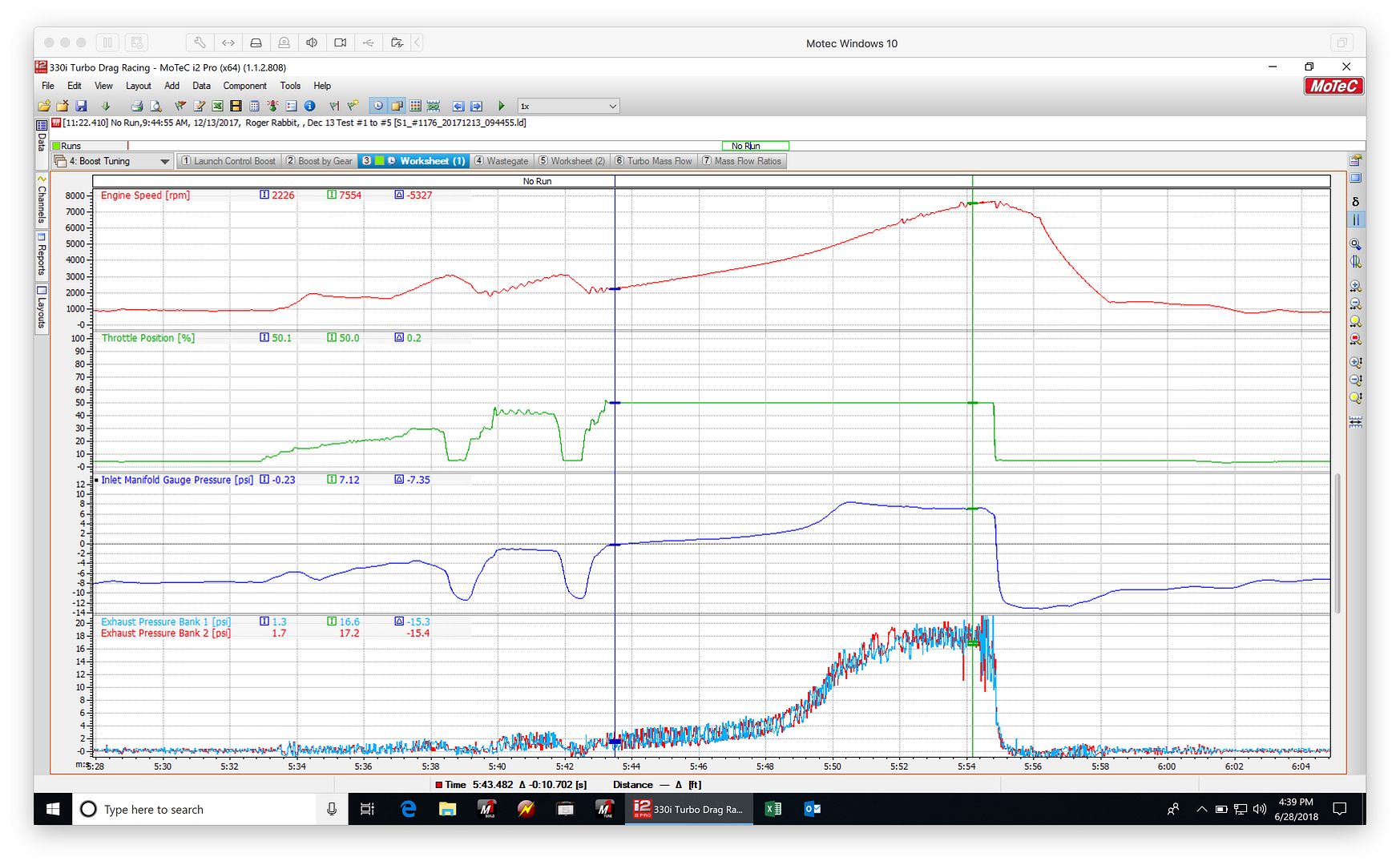
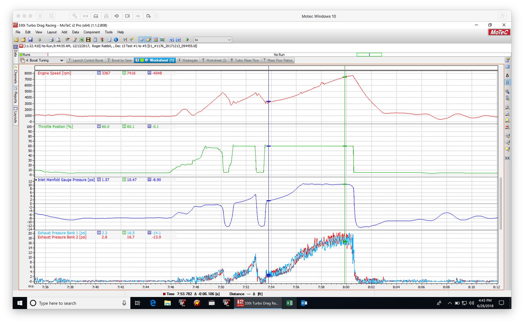
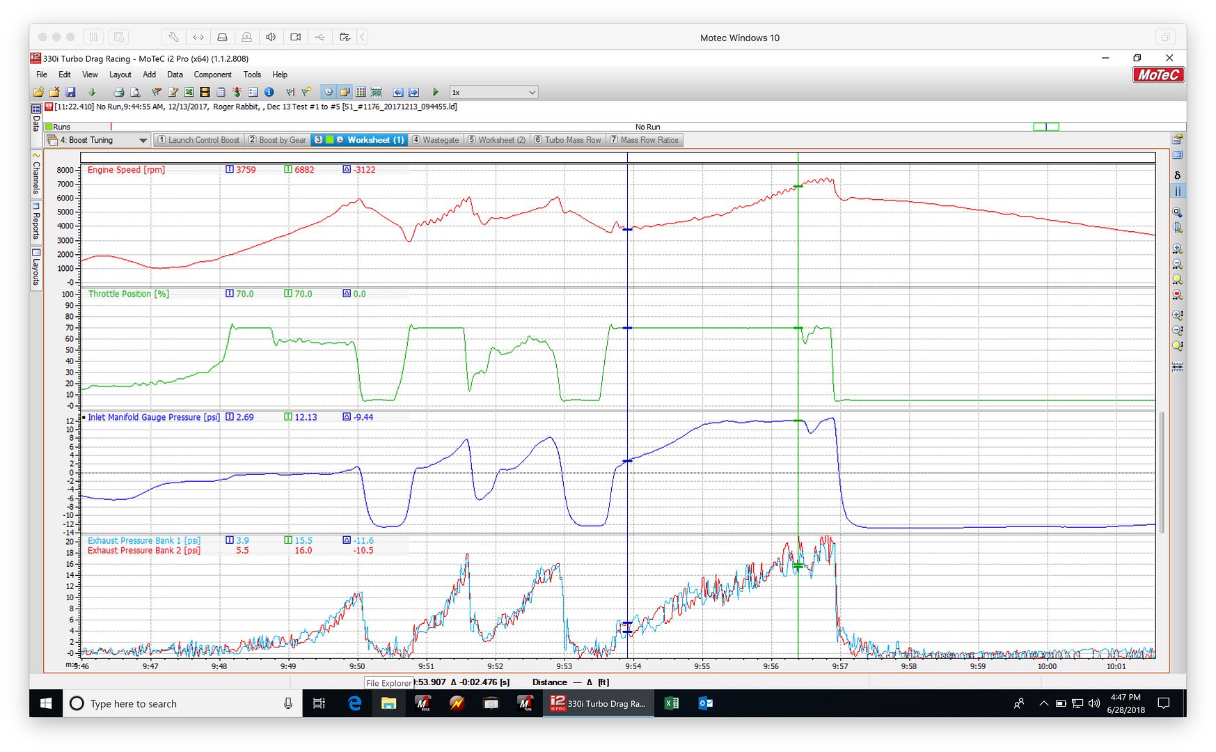
Because I have a Development License for my Motec M1 ECU, this lead me to experiment with Option #7. Using a 10.8 PS WG spring, and EBC turned off, I did controlled testing on a constant grade to evaluate the effects of varying the throttle position. This is what I found from 30% to 70%:
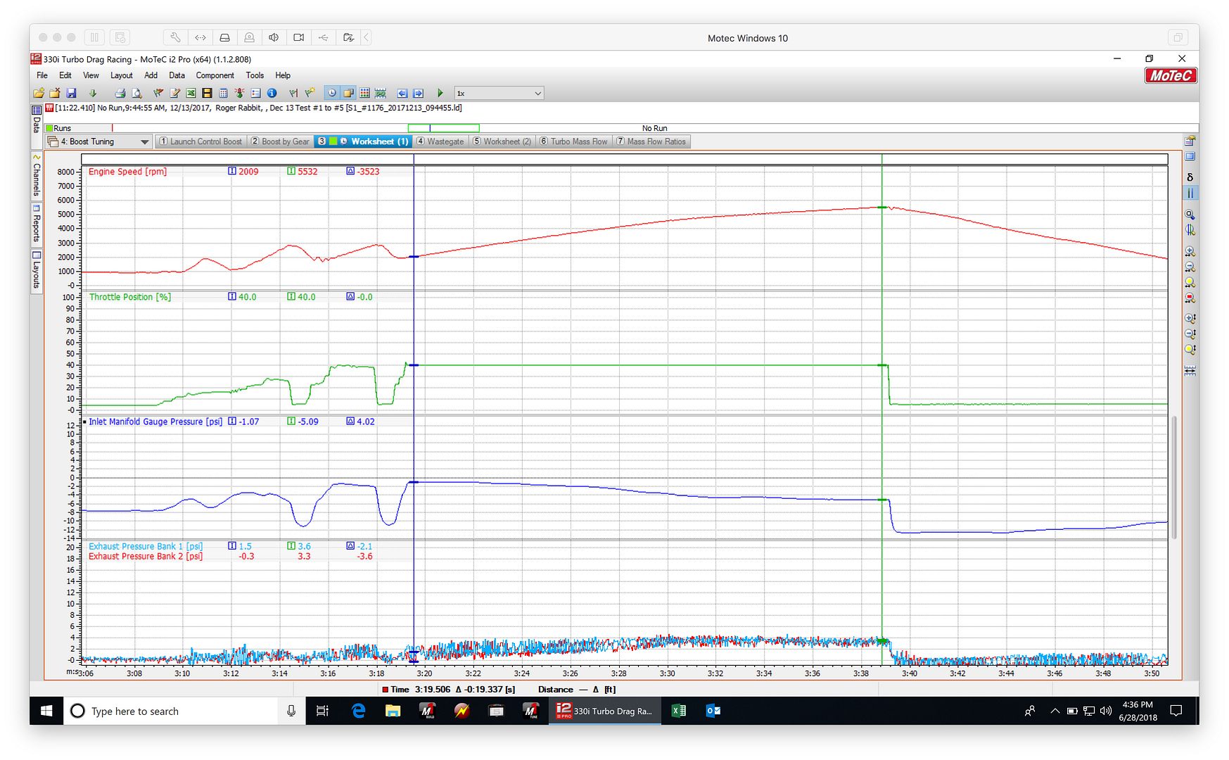
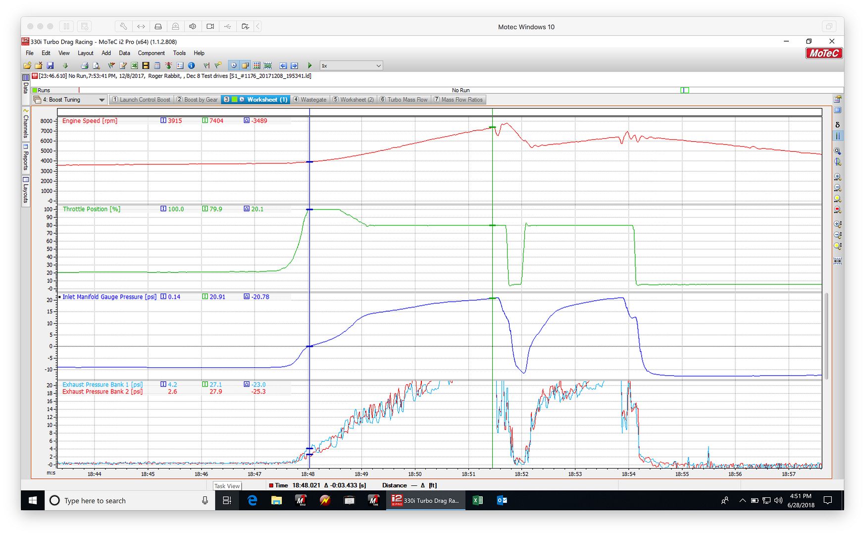
This is a more advanced method test that I did earlier with 80 % throttle:
Despite the limited time testing with the GTX4088R, and before I had a chance to investigate any of the waste gate options listed above, I decided I wanted a bigger turbo. I've since bought Forced Performance HTZ GT4205R turbo, and I'm now in the process of fabricating all of the charge pipe work and exhaust again. The question remains: How do I control boost with this highly compromised waste gate situation?
Below are my calculated boost targets for each gear based on known tractive force limits:
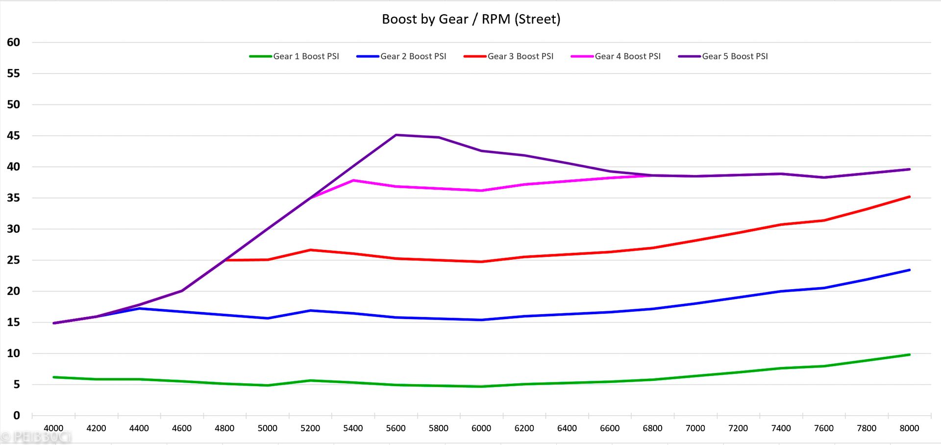
Gears 1, and 2 need significant boost regulation, but these are relatively "low" engine loads so I'm not excessively worried about exhaust back pressure. Gears 3, 4, and 5 are higher load where you would not want to generate additional back pressure.
There are a lot of OEM boost control strategies that use the throttle. It's normal, although not ideal. BMW N20 engines are one example. However getting it to intervene smoothly could be difficult. You don't want it to feel like you just hit a brick wall, and the screenshots look like a drastic intervention to me. The OEM applications can pull it off because they use model-based and torque-based controls which are not possible here. Basically there is an algorithm that calculates airflow, spark, etc needed to achieve the target torque, models of each actuator (turbo model, wastegate model, etc), and an arbitration algorithm to choose which actuator to change to achieve that torque.
I can't tell what engine that is from the pics. Does it have intake and exhaust VVT like say a BMW N54? You could attempt to drop boost or otherwise control load by changing cam angles for example. Also, is it absolutely necessary to have minimal exhaust restriction? I suppose with a turbo of that class you need to with spool. You could try installing a cat for example. Or if you can make it all fit, a tubular manifold with separate wastegates for each scroll.
Raymond,
Thanks for the detailed reply.
The engine is a BMW M54B30, with VANOS and a manifold plenum divider flap system called DISA. I haven't played with the intake or exhaust camshaft angles yet to reduce boost, I have primarily been targeting turbo spool and absolute power generation.
I have a catalytic converter, but have removed it due to the use of a 2 step launch feature.
Ok, so if I remember correctly that engine has something like a 30-40 degree range on intake and exhaust VANOS. You are using stock cams, correct? Can you post your cam phasing maps? Have you been retuning or at least evaluating the VANOS with each turbo? For example if you are trying to limit boost in lower gears you can reduce scavenging (reduce overlap) by running the exhaust VANOS with less retard. You tune your intake VANOS to best closing timing (trapped mass and effective compression ratio) and control your overlap and spool with the exhaust VANOS. This is how the torque and model based algorithms operate. They have a scavenging/spool mode based on valve timing.
Yes, 40 degrees on the Intake, and 25 degrees on the exhaust.
Cams are from Schrick: 272 / 256
My current VANOS maps:
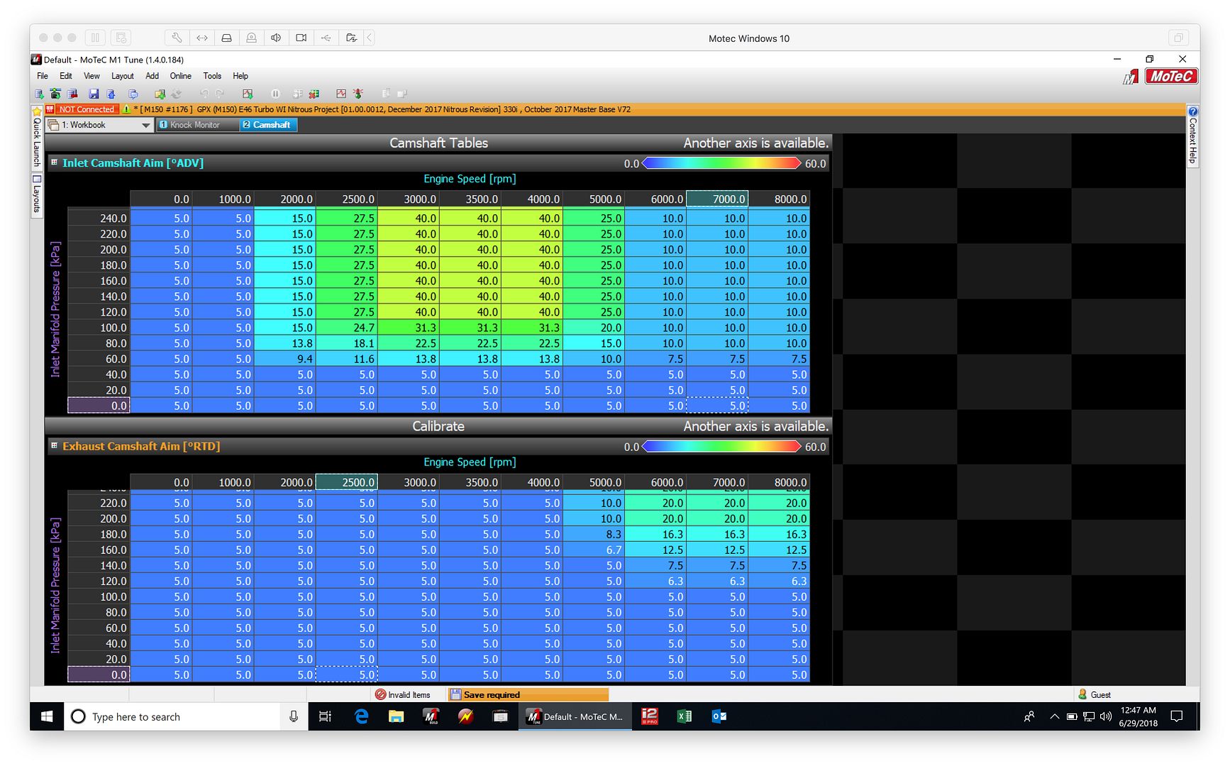
These are obviously far from being fine tuned. I don't have easy access to either an inertia or load control dyno, so I'm left to do road tuning with lots of data logging. (Currently logging over 700 channels of data at up to 1000hz sample rate)
I'm intrigued to try to use both the camshaft and camshaft phasing to help control manifold pressure. While I'm aware of the effects of overlap, I hadn't actually considered using it as part of the boost control strategy.
I've got much more to share, but I've got a date with my wife.....
See if anyone has reversed engineered the stock maps. Your exhaust VANOS is way off I can tell you, intake needs significant work too.
Bigger intake cams close later and need more intake advance at low end for example.
I do have the stock WOT VANOS maps, but this engine wasn't a turbo engine from the factory. Also, the cylinder head is ported, and I don't mean just a "smooth out" job. I've also just changed the intake manifold, so the VE of the engine is very different from OEM.
One of my main questions is: Why don't OEMs attach waste gates to the outside radius of the turbine housing scroll?
Borg Warner puts the IWG at the entry to the scroll with the EFR turbos, but they have proven to be highly in-effective at managing boost if you have a very efficient turbo manifold like the one that I'm currently using. (We are seeing boost creep up to 22-23 PSI before stabilizing, making lower boost targets impossible)
Of the 7 options I've listed above, running a waste gate or 2 on the turbine housing is the most recommended by experienced fabricators. Changing the manifold would create more problems than it solves from a packaging and longevity perspective.
Also, for those that haven't picked it up yet from the photos:
Bank #1, with Cylinders 1-3, has a straight shot at 1/2 of the WG port.
Bank #2, is compromised. Cylinder #4 has a straight shot. Cylinder #5 has to make a 120 degree turn, and Cylinder #6 has no direct path to the WG port. (It merges with the flow from Cylinders 4 & 5 just before the turbine housing)
While I am concerned about the reduction in WG flow that this situation creates, boost control isn't the only variable affected. My issue with this is that you are affecting the VE of each cylinder differently, as you open the Waste gate. So rather than have a fixed VE curve for each cylinder based on manifold pressure, the engine will see less airflow through cylinder #6 than cylinder #1, and this will vary based on the difference between the boost target and manifold pressure.
I don't have individual Lambda sensors on the manifold, but I'm now looking to add them. (At least to do the initial calibration)
I'm starting to see the wisdom of this torque demand map, versus looking at manifold pressure alone.
You could run an exhaust manifold like I currently have, that is incredibly efficient at non-bypassed flow, and use a combination of methods to reduce tractive force applied to the wheels.
Camshaft phasing could be manipulated to reduce the total charge volume per cycle.
Throttle position could be closed to reduce the total charge volume per cycle.
Ignition timing could be changed to reduce the torque output of each charge volume being burned.
TL;DR your cams are too big for boost unless it's some kind of drag car, wastegate and throttle closures are a band aid. The whole point of VANOS is to use the VANOS for overlap, not have a big overlap in your baseline cam position.
If you can post the stock VANOS maps that would still be very helpful. I was aware that this engine wasn't turbo from the factory. I'm familiar with the N54 VANOS maps. I am attaching the stock N54 ones here; the aftermarket is running more aggressive than this. Yes your engine isn't direct injected but directionally you can understand where to go with these maps.
Please note that these maps are in camshaft centerline degrees (absolute), not in relative degrees of advance or retard like your Motec maps. Compare the upper left corner (idle, baseline value) to the right most corner to understand what the relative position is. So the baseline position is about 125 on the intake side, and 132 on the exhaust side. Basically from 1500 they are retarding 30 degrees at WOT on exhaust side and advancing 40 degrees from. I looked up your cams on the Schrick website. It says part #0261 E1 721-DV0 , 272 degree duration, centerlines/baseline position at 126 degrees on intake and 86 on exhaust.
Intake valve opening: 10 deg before top dead center intake
Intake valve closing 82 deg after bottom dead center intake
Exhaust valve opening 50 degree before bottom dead center exhaust
Exhaust valve closing, 42 degrees after top dead center (!) intake
Do you have a cam card that came with the cams? I am wondering at how many millimeters lift these valve timings are in reference to. Either way, compare the cams to an N54 engine's stock cams:
Intake valve opening, 23.5 degrees after top dead center intake
Intake valve closing, 42 degrees after bottom dead center intake
Exhaust valve opening, 52 degrees before bottom dead center exhaust
exhaust valve closing, 24 degrees before top dead center intake
You really should consider smaller cams. I know all the marketing says bigger is better, but your locking position has huge overlap which is scavenging the hell out of your turbo on the exhaust side and causing almost a miller cycle effect on the intake side due to the late closing timing. So now you are advancing the intake cam which raises the effective compression ratio and trapped mass, but increases overlap. Your VANOS mapping is making things worse for controlling boost.
Switch to the 248 cams or even go back to stock, and totally retune your VANOS. I really don't like how late any of those exhaust cams they offer close. They're not optimized for a double VANOS boosted engine at all. They open too late, which is bad for high power, and close too late which is bad for low end, because of the VANOS.
They're basically N/A race cams with valve timing designed for non VANOS. You can just tell by the timing that they didn't take into account VANOS angles. It's too bad you can't use N54 cams on your engine.
I don't have a cam card for the cams, but I have previously had Schrick do custom camshafts for me, and they provided a cam card for those and also the 264/248 cams for comparison. On that cam card, they seem to use a lift marker of 0.1mm for the quoted numbers.....which as you know is not the industry standard for aftermarket cams. (Normally 1.27mm or 0.050") In that case, the 264 deg cams worked out to 221.8 deg cams with the 1.0mm lift marker provided by Schrick. Ironically, at a later date I got another Cam card sent to me with a 1.27mm lift marker, and the 264 deg cams worked out to 216.6 deg.
I mention this just from the perspective of duration, not the centreline. They didn't seem to shift this at all.
I can buy individual cams, but another option is to have a custom set made for me. (8000 RPM peak, 1200hp target)
In Pipemax, these cams already showed to have excessive lift and duration......I think the intake's calculated peak was somewhere over 9,000 RPM.....
Can you use this intake cam and a stock exhaust cam? I have no idea if that will work in terms of all the hardware necessary. It's really the exhaust side that's messing you up I think. The intake cam is big but the problem is the exhaust valve closing angle leaves you with way too much overlap at locking position, and since the exhaust cam can only retard, it just makes it worse.
On the intake side the 80ish degrees ABDC closing is good for high rpm. You can make power probably up to 7000-8000rpm, and if you can advance it enough to get a good closing timing for medium rpm. Then at low end use an earlier centerline exhaust cam and just retard it for spool only.
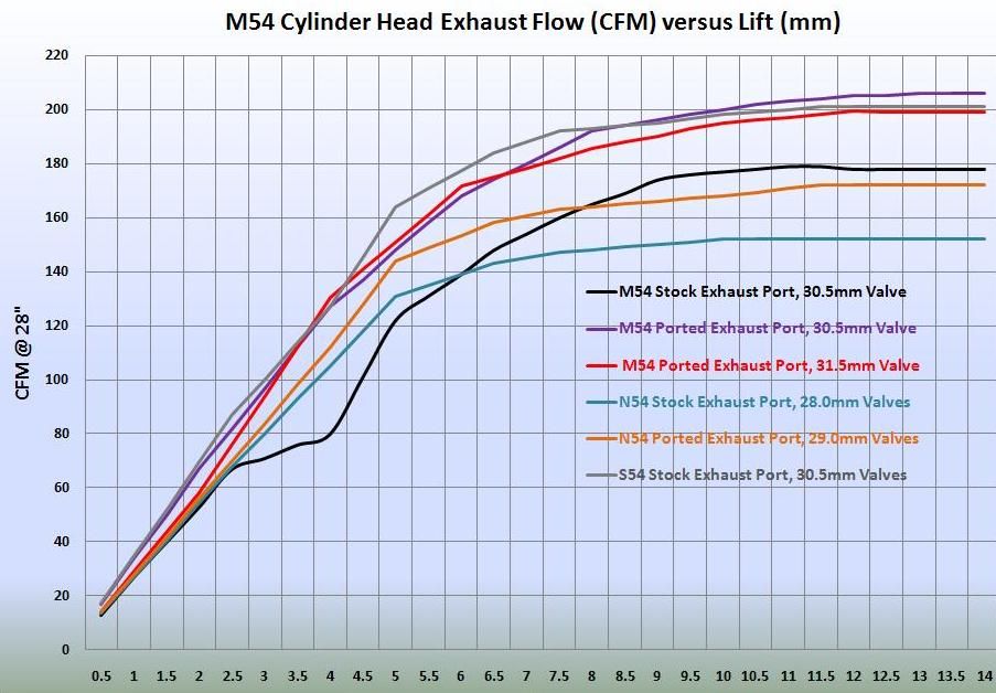
There's something else relevant to the conversation that I would like to share. Below is flow bench data that I have colated; most of it I have paid for to have done for my own projects over the years.
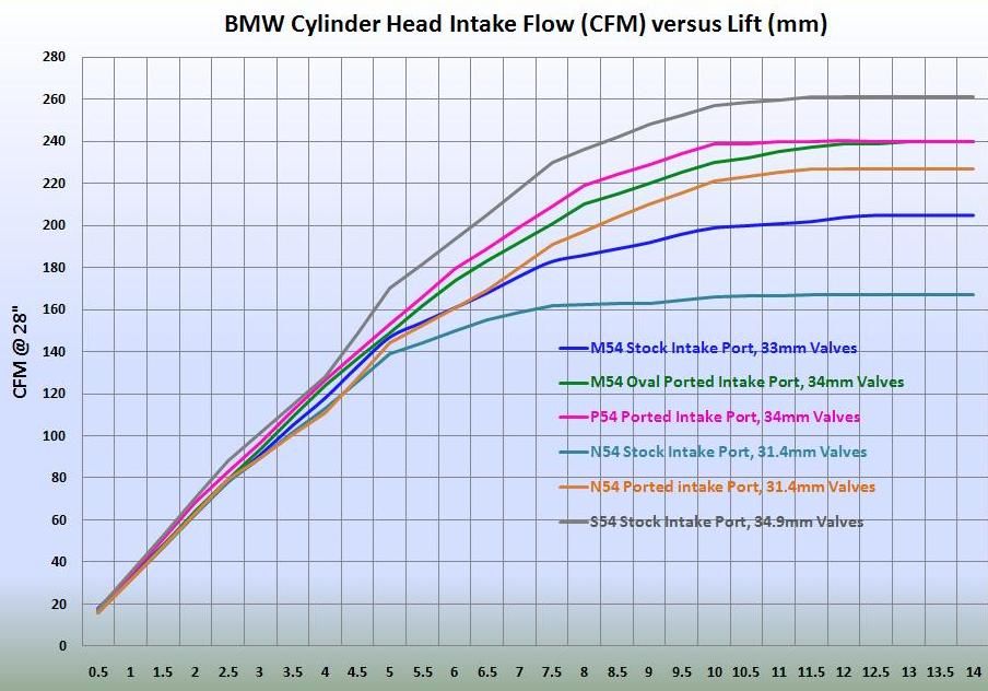
The cylinder head that is currently being used on my engine:
M54 Oval Ported Intake / 33mm Valves
M54 Ported Exhaust / 30.5mm Valves
Those flow results follow the expected trends. Direct injection heads flow poorly compared to port injection, especially port injection heads designed for high revving power. For a cylinder head there is always a tradeoff between tumble coefficient and flow coefficient at a given valve angle.
If you put those heads on a tumble bench you'll see there's much higher tumble on an N54. And in regards to Valvetronic engines, you put an N55 (and equivalent B series engine) or S55 (current M engine, twin turbo Valvetronic) on a swirl bench, you'll see that they have much higher swirl when the valves are doing offset lift mode. The offset lift mode is purely a fuel economy thing during cruising. Valvetronic doesn't give you power directly; it just allows you to use a better flowing head and still get the fuel economy benefit. But enough about Valvetronic, since this is a port injected dual VANOS head.
Getting back to your engine: So the large ports, big intake cam with late intake valve closing timing and big turbo are good for high rpm power. The exhaust cam is counterproductive though because of the way VANOS works. The cam has a later exhaust valve opening timing, which is good for low end due to the increased expansion stroke. It's got a late exhaust valve closing timing, which gives you a big overlap and is good for low end spool and is probably contributing to your boost control issues.
The problem is that exhaust VANOS only goes in one direction relative to the locking position. It only retards, it doesn't advance. You need to ADVANCE the exhaust cam at high rpm. You're already WAY retarded on the exhaust side, maybe even too retarded during spool up when you want to have max retard. The most advanced the exhaust cam can go is at the 0 retard point (baseline position). In your case that is the centerline angle of 86 degrees which is insane for a baseline position. That means your centerline is about 60 degrees when you retard it. That's just nuts. It's useless overlap.
Basically you have an S2000 stuck in VTEC and then you put a turbo on it.
Raymond,
Thank you again for the very detailed explanation and insight.
There is good news: I can rotate the splines that are part of the VANOS mechanism.
BMW doesn't sell the VANOS spline or attaching bolt to the camshaft, they only sell the complete cams if you have to replace something. The reason is that the spline doesn't have a locking pin to orient it, it is simply put into a jig on the cam, and then bolted to the camshaft. I had problems previously (As far back as 2009) with cam timing, so I start to investigate this further. What I found was that when the engine rev'd faster than stock, the VANOS put so much torque into the rotation of the camshaft that the spline would move. Then the camshaft would give an error, because in the resting state it was out of position.
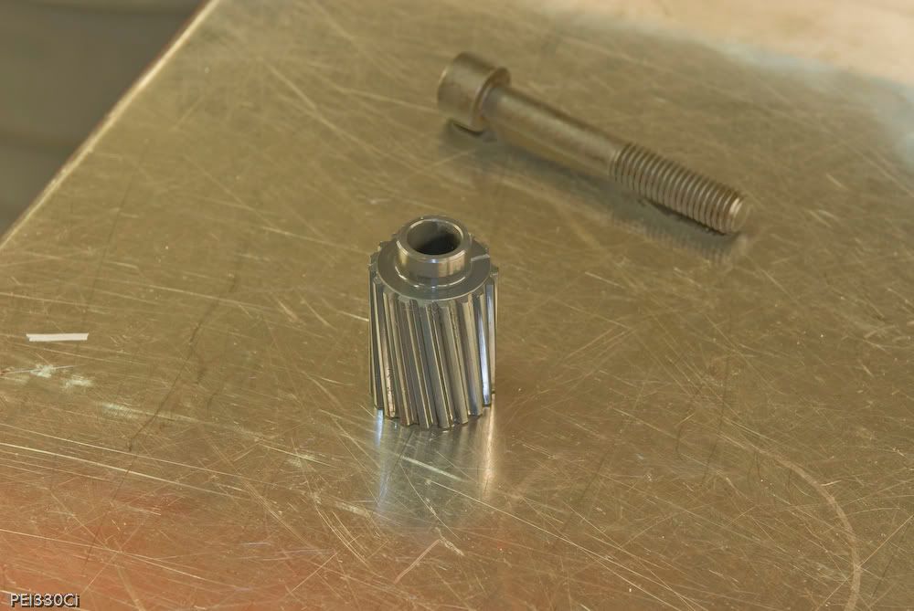
This is the spline:
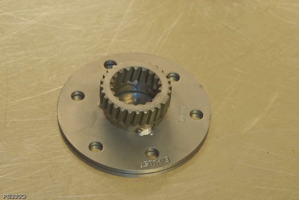
This is the tool to align it on the camshaft:
And here is my solution to keep the spline from rotating on the camshaft:
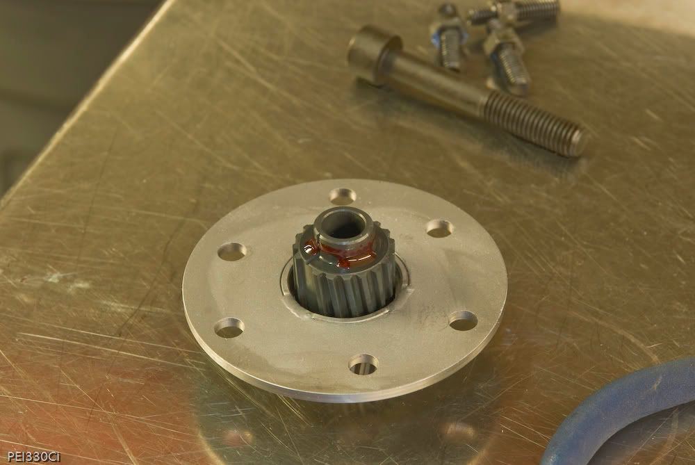
So the splines on my current cams are loctite'd on, but I can pull them off and rotate them to change the resting camshaft position.
If you're sure it is safe to do so, try to advance your exhaust cam 20 (even 30) crank angle degrees at the baseline position. I'm not promising miracles here. but it will help your top end by the 0 position opening earlier to evacuate exhaust gases, and it will help low end because you can now control overlap better with VANOS angles. Your minimum overlap is less and your scavenging is reduced, blowing less air through the engine to needlessly overspool the turbo.
You may still need wastegate improvements.
In the short term for your current cam configuration, I would set the whole exhaust VANOS map to 0. On the intake side, carry the high load yellow 40 degree area down to 2000rpm for better low end.
I have in the past found that what BMW reports in their "specs", doesn't measure out. For example the static compression ratio of the M54B30 engine is listed at 10.3:1, but I measured a completely stock engine to be 9.9:1. I think to start with, I'm going to mount a degree wheel to the engine, along with a gauge on the valves, and measure what my current setup is actually doing. With a little bit of compressed air, and a wrench on the cam core, I think I can rotate the VANOS through it's control range to confirm both it's motion. Lastly, and most important, I should lock the engine at TDC, and measure how much rotation I have of the cams before piston to valve contact is made.
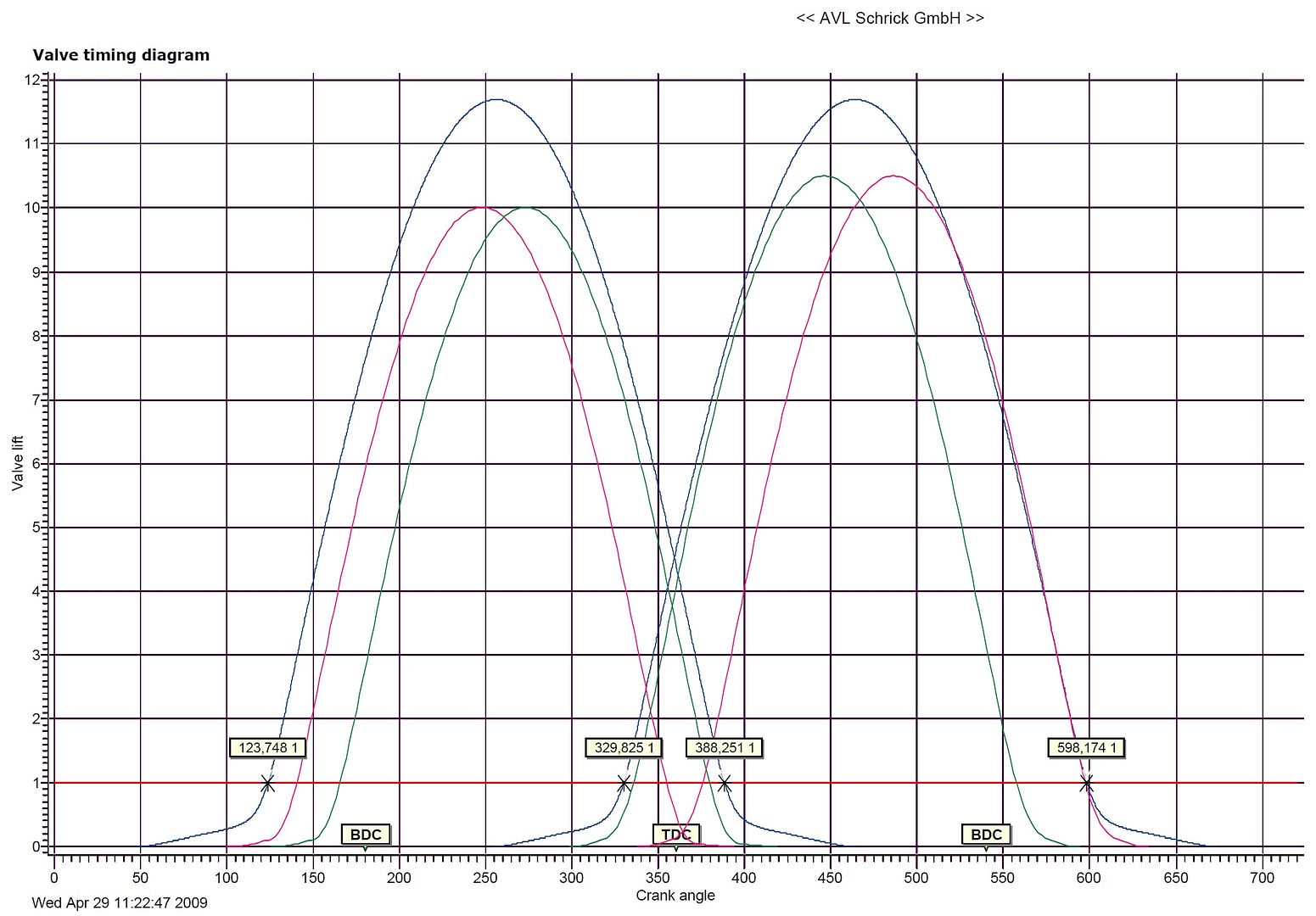
This is part of the previously mentioned cam card from Schrick comparing the 300/296 custom cams, with 264/248 cams:
Any thoughts on putting an MVS waste gate directly on each scroll of the turbine housing?
Ohh I didn't realize Schrick is owned by AVL. That makes a lot of sense. I also didn't realize your cam cards came with real cam profile diagrams probably from actual Cam design software. I was thinking this was some muscle car stuff where you just get these oldschool vague measurements. AVL is a well known Austrian company and basically the biggest automotive engineering services firm on the OEM side that is independent from a major supplier like Bosch. I've worked with them a lot. So it looks like those advertised durations are just muscle car catalog crap, and we need to see these cam cards to understand what's going on.
The 1mm lift reference point shown above is actually a standard reference point for OEM cam design. And the Austrians/Germans like to list their valve events in degrees ATDC firing like you are seeing that diagram.
It looks like the above cam diagrams show your big custom cams for whatever application that was and then the VANOS range for the 264 cams, correct? Same cams at baseline position and then fully phased? Those 264's actually look pretty good for your application. The baseline position has almost 0 overlap, so you can use the VANOS to control spool, just like any other modern turbo engine with intake and exhaust variable valve timing. In contrast those 300's are way too big for boosted + dual VANOS unless it's one trick pony kind of application and all you care about is operating in a very narrow range with highly tuned parts to run there.
Do you have a diagram like this for the 274 cams we've been talking about, the ones on the engine right now? The specs I gave for the N54 engine's stock cams were measured on the engine at 1mm lift.
Also, one wastegate per scroll is a good idea, although you may need a tubular manifold to do it, rather than trying to actually tap into the turbo... It's very common on engines that boost control problems like Rx-7's. The other option is to run one big single gate and pull one big runner off of each scroll, merging into the big single.
OR if you decide you don't care about low end, switch to a monoscroll turbo, maybe even V band inlet. Monoscrolls are better for top end power due to lower backpressure.
Now I think the jury's still out on those 274 cams. I really want to see a cam card like above, or barring that I would like to see the measurements at 1mm lift (IVO, IVC, EVO, EVC) for both baseline position and fully phased.
FYI, I'm still trying to get the Cam card from the manufacturer.
The vendor that I purchased the cams from, doesn't reply to my emails. (They are known for horrible service, so this didn't surprise me)
I've reached out to another vendor for help....
I didn't get the cam card, but I did turn everything into a Cam lobe centreline graph for comparison:
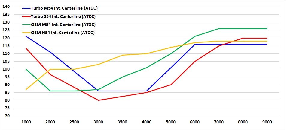
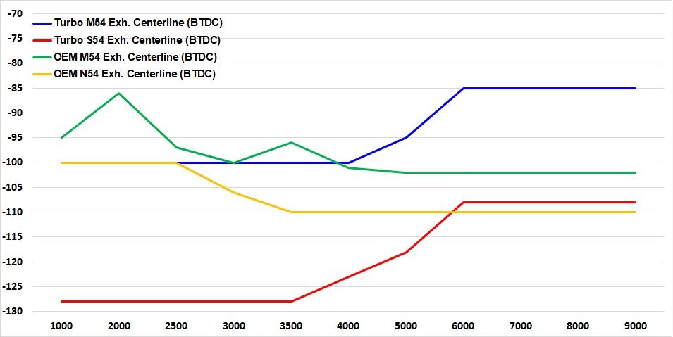
Now I see what you're talking about with the exhaust cam!
My mistake was that I used the map from the turbo S54 straight up, without considering the resting state of the VANOS.
The good news is that I definitely can rotate the helix spline on the exhaust camshaft to move it's resting state to -125 Deg BTDC.
Cool keep us posted.


