219 | Getting Wideband AFR Data into VCM Scanner
Summary
If you want to get the most out of the HP Tuners VCM Scanner software, then you’re going to want to input a Wideband directly into it so the data can be logged and overlaid with the rest of the engine parameters. In this webinar we’ll demonstrate the best way of getting your Wideband to communicate with the VCM Scanner.
| 00:00 | - Hey guys, Andre from High Performance Academy, welcome along to today's webinar where we're going to be looking at the options available for you to get a wideband air fuel ratio meter into the VCM scanner software if you are tuning using the HP Tuners package. |
| 00:18 | And getting solid dependable wideband air fuel ratio data is really one of the keys when it come to adjusting your calibration, making tuning changes. |
| 00:27 | We obviously need to accurately know what our air fuel ratio is so that we know what sort of changes we're going to need to complete with our tuning and the scale of those changes. |
| 00:39 | The other aspect though with getting wideband air fuel ratio data into the VCM scanner software is that it does open the doors to a lot of the more complex analysis and scanning options available there such as using the histograms which is a great way of speeding up your tuning regardless whether you are running a MAF based tune and you want to adjust your mass air flow sensor scaling to get that accurate or if you've gone to a speed density calibration and you want to adjust your volumetric efficiency table, using the math parameters and the wideband input is essential to being able to do that. |
| 01:14 | As usual we will be having questions and answers at the end of this particular webinar so if you've got anything that I talk about during the webinar that you'd like me to dive into in a little bit more detail, please feel free to ask your questions in the comments and the team will transfer those through to me. |
| 01:32 | I think one of the first places that we need to start is why do we need a wideband air fuel ratio meter in the first place? And I know that a lot of tuners do their tuning or a lot of their fuel tuning at least using the factory narrowband sensors. |
| 01:48 | There's pros and cons with doing this. |
| 01:51 | One of the big limitations however is if we are going to be relying on the narrowband input then this means that you can't really do any tuning when you're not in closed loop mode. |
| 02:02 | Those narrowband sensors, as their name suggests are only accurate at or very very close to the stoichiometric air fuel ratio of 14.7:1 So that's fine when we're at idle and when we're at cruise, even under moderate load when we are in closed loop mode and the PCM is targeting the stoichiometric air fuel ratio however when we go to wide open throttle, we will be wanting to run in power enrichment mode where we are going to be targeting a richer air fuel ratio. |
| 02:30 | And under these conditions we are ignoring the narrowband sensors but they'd also be useless to us anyway, they simply can't give us accurate data when we're that far away from the stoichiometric air fuel ratio. |
| 02:42 | So the solution here is we do need a wideband sensor. |
| 02:46 | So I'll just elaborate on this a little bit because a lot of people do use the narrowband, either the short term or short term plus long term fuel trims that we're going to have in our scanner anyway to help them calibrate the mass air flow sensor scaling or the speed density volumetric efficiency tables. |
| 03:03 | But again even if you are using those, you're only able to do that in closed loop mode, it won't help you with the power enrichment area of your tuning. |
| 03:12 | And the other aspect is that it is important to understand that the narrowband sensors are reactive, they're not predictive. |
| 03:19 | So in order for them to show you a trim, we already have an error present. |
| 03:23 | You're also going to obviously see that your short term and long term fuel trims are constantly moving. |
| 03:29 | So in my opinion, it's a less accurate way of doing your tuning. |
| 03:33 | We're much better to use a wideband and then disable the closed loop control completely so we can rely on that wideband. |
| 03:42 | OK so when it comes to getting a wideband input into your VCM scanner, there are a couple of options here. |
| 03:52 | What we can do is, well there are also a wide range of wideband air fuel ratio meters and gauges on the market that are compatible. |
| 03:59 | There is a list on the HP Tuners website that you can go through. |
| 04:04 | So it's obviously a good idea to make sure that you are going to be working with a supported brand. |
| 04:11 | That list however supports the majority of the popular choices most are going to be making anyway. |
| 04:18 | So once you've got your wideband meter there are a couple of options of actually getting that data into the scanner. |
| 04:23 | The first of these is to use an analog voltage output from our wideband meter and wire this directly into your MPVI interface. |
| 04:33 | So there are a couple of options with the MPVI interface. |
| 04:36 | So I'll just bring up, I'm actually using for today's webinar the old MPVI1. |
| 04:41 | I've got the MPVI Pro interface here. |
| 04:44 | So this has this little green connector on the side of it which has some analog to digital inputs. |
| 04:50 | So this is a perfect place to wire in your wideband sensor. |
| 04:54 | If you are working with the newer MPVI2 interface, for a while you had no options, however as HP Tuners rolled this out, they have added their pro feature set which is essentially exactly the same, you've got the option to pay for the pro feature set, it's a little bit more money and then you can wire in a wideband sensor to the little adaptor that you can purchase as part of that pro feature upgrade. |
| 05:22 | So that's how you can get your data in via analog voltage. |
| 05:26 | And we're going to go through a little worked example of how to do that shortly because it is problematic and I know a lot of people really have trouble, including me, getting really accurate data in this way. |
| 05:37 | So we'll see how that can be done. |
| 05:39 | The reason it is problematic though, and this doesn't just go for the HP Tuners platform, this goes for basically any ECU where we are wiring in a wideband air fuel ratio sensor using analog voltage. |
| 05:52 | We are very susceptible to the data being affected by any ground offsets. |
| 05:59 | So what this means is that if there is a voltage offset on the ground or zero reference, this can affect the reading that we're going to see in our ECU or in this case our VCM editor scanner software. |
| 06:13 | And this is a real problem because particularly if you are using a wideband controller that doesn't have a gauge or a display of its own, you've got no way of seeing what the actual air fuel ratio data should be. |
| 06:26 | And of course when we've got a number sitting there on our laptop screen, we generally will tend to trust it. |
| 06:33 | And we might find that it's completely inaccurate and giving us completely inaccurate data. |
| 06:39 | What I mean by those ground offsets is if the output from the wideband meter is let's say between 0.5 and 4.5 volts and let's just say for argument's sake that with a value of lambda one, our stoichiometric air fuel ratio, the wideband is outputting 2.5 volts. |
| 06:55 | If a ground offset ends up with that 2.5 volts actually sitting at let's say 2.6 volts which wouldn't be uncommon, that can have quite a significant impact on our readings. |
| 07:09 | So we want to be really mindful of that. |
| 07:10 | It's something that I know a lot of even professional tuners really aren't aware of, they completely overlook and while in a lot of instances the ground offset may be small enough that it's not going to play a significant role, it's also very easy to find situations where it offsets the air fuel ratio readings by half a point or something of that nature. |
| 07:31 | So really is something we need to watch out for. |
| 07:34 | The other option is that we can input this data via a serial link directly to our laptop. |
| 07:41 | There are also options, I'm going to do another webinar at another time getting information in via another type of wideband air fuel ratio meter via CAN. |
| 07:51 | But essentially we're looking at a way of getting the data into the VCM scanner software where the integrity of the data is guaranteed, there's no voltage offsets that can affect it. |
| 08:03 | It is being sent over either CAN or a serial data stream, and the integrity is 100% guaranteed. |
| 08:11 | So understandably that is my preference. |
| 08:12 | It's the same with the aftermarket ECU tuning world, where possible I'm a huge fan of using the CAN based wideband controllers to input to our ECU where we can make sure that the integrity of that data is going to remain accurate. |
| 08:29 | Alright so what we're going to do is start by looking at the serial interface connection with our LM2 wideband controller. |
| 08:39 | So I'll just show you, if we just jump across to my laptop screen. |
| 08:43 | This is what's sitting actually up on the dash ahead of me. |
| 08:47 | So we've got our Innovate LM2 sitting up there. |
| 08:49 | This is probably my wideband of choice and I know there's a lot of people out there who actually don't like the Innovate product. |
| 08:58 | I hear a lot of people complain about reliability problems with the Innovate LM2. |
| 09:03 | Personally I haven't seen this issue. |
| 09:06 | I've used these through my career here at HPA as well as for probably 10 years while I was running my professional workshop and I had great results from them. |
| 09:17 | Definitely had their fair share of minor issues but nothing that I would really put down to a major reliability problem. |
| 09:24 | So I like the fact that I can suction cup it to the windscreen there and while I am road tuning in particular, gives me the ability to just view the air fuel ratio data out of my peripheral vision, just giving me the ability to make sure that my air fuel ratio is on track. |
| 09:39 | Alright so anyway, back to our picture. |
| 09:42 | There are a couple of options to get that serial information out of the Innovate LM2. |
| 09:47 | So at the top here we've got the conventional port that we use for programming the LM2. |
| 09:53 | And on the side here we've also got the serial in and out. |
| 09:59 | So this is how we can daisy chain the LM2 with other Innovate products. |
| 10:03 | So when I first started trying to get this serial information into the VCM scanner, I would have probably wasted 10 or maybe 15 hours messing around, hugely frustrating trying to get this data out of the LM2 and into the scanner. |
| 10:18 | And the reason, one of the reasons that I've done this webinar is because I know that the problems I was facing are shared with a lot of other people. |
| 10:25 | There is a really long thread on the HP Tuners forum with people talking about serial inputs, not just the LM2 but the other widebands that are supported. |
| 10:36 | And basically it seemed like there was about a 50% hit rate of people that could get the LM2 data into the scanner successfully and others that didn't. |
| 10:45 | Not particularly helpful but HP Tuners basically at the end of that thread closed it all down and said that they're not supporting it anymore. |
| 10:51 | So not hugely helpful but anyway I've managed to get the data in with reasonably reliability and I wanted to show you how I've done that. |
| 11:00 | So the first point is that if you want to do this, get that data into your laptop, you cannot, at least in my experience, use the serial to USB, the USB connection I should say at the top of the LM2. |
| 11:13 | That will not work. |
| 11:14 | While we can program it through that connection, via that USB cable, it will not work to get that data into the VCM scanner software. |
| 11:24 | Instead what we want to do is use the four pin Innovate serial connector on the side. |
| 11:31 | The other important aspect here is that there are two of these connectors. |
| 11:34 | The top one is for serial in, the bottom one is for serial out. |
| 11:38 | So we want to be using the bottom one there, our serial out. |
| 11:42 | Now that particular connector from Innovate will terminate in a D9 serial connector. |
| 11:51 | So then we need to use a USB to serial adaptor to get that data into our laptop. |
| 11:57 | Now once we've done all of that, we can then go into our VCM scanner and we can bring in our Innovate product. |
| 12:05 | So we'll just head across and we'll have a quick look at that. |
| 12:08 | I'll just get rid of that. |
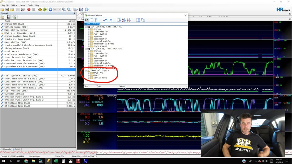
| 12:11 | So if we click here and we add a channel, what we can do is we can go down to serial port, down the bottom, so these are for our external inputs, these aren't the channels that we can log from the factory ECU. |
| 12:25 | And we've got our options there, AEM, Innovate, Plex and Daytona. |
| 12:31 | Obviously we want Innovate. |
| 12:33 | I've actually already selected these so we are logging Innovate the status which is quite helpful because we can see if there's an error whether it's warming up or whether it's running normally. |
| 12:43 | And then we've got our air fuel ratio data so those two channels are being logged. |
| 12:48 | So that's how we get that data in and then we can hit record, start logging. |
| 12:56 | I'll just close this down so we can actually see those two channels are sitting in there. |
| 13:02 | And you can also notice on the left hand side here you can see the little icon showing you that these are from an external input as well which is just a little reminder of where that data's coming from. |
| 13:14 | Now that is on its own, in my experience, still not always a bulletproof way of getting that data to come up and generally what we'll end up with, is we'll press record to start logging data from the vehicle and straight away you can see that those two channels have disappeared. |
| 13:32 | So we've got no data, not overly helpful for our pusposes. |
| 13:36 | Now the reason this happens is that when we start recording, the VCM scanner software will poll the serial ports, the USB ports looking for that data. |
| 13:45 | If it doesn't find what it's looking for, those two channels go away. |
| 13:49 | And what I've found to be a pretty bulletproof way of getting around this is prior to hitting record on the VCM scanner software, what I will do is I will run the LM Programmer software so if you've got the Innovate LM2, any of the Innovate products, you probably want to download the LM Programmer software, you're also definitely going to need it for the next step that we're going to look at. |
| 14:16 | And that allows you to control the way the LM2 operates and in particular the outputs from the LM2. |
| 14:23 | And it seems to be enough that if we run the LM Programmer software and the LM Programmer software will then look at the USB ports on your laptop, if it finds the unit it will then open up. |
| 14:35 | Once you've done that you can close LM Programmer, start scanning and that seems to be my little trick that gets that data coming into our scanner pretty reliably. |
| 14:46 | Alright so that would be my preference, that's definitely my recommendation and ultimately there's really no reason not to bring that data in via serial. |
| 14:54 | As I've said, more reliable. |
| 14:56 | But the other aspect here is that it's free essentially. |
| 14:59 | You're going to need a USB to serial adapter, you're going to need the little four pin output from the Innovate product but from there it's good to go. |
| 15:08 | On the other hand if you are looking at the MPVI2 interface, I think off the top of my head, the pro feature set is around USD$250 and then you're going to need the pro feature cable as well to input that data which is I think about another USD$35 so fine if you're going to be adding additional inputs over and above a wideband but as I say just for wideband itself, not strictly necessary. |
| 15:34 | OK so let's jump into the other option, if you are determined to make your life hard and you want to bring that in via an analog voltage input then obviously, as I've already kind of touched on, making sure that it's calibrated accurately is going to be the key to your success. |
| 15:49 | Now it's a little hard for me to show this demonstration because the Innovate LM2 is a bit finicky about how you go about this but I'm going to show you the process. |
| 15:59 | After this we're going to move into questions and answers so this is probably a good time to remind you that if you've got any questions, please ask them. |
| 16:07 | So what I'm going to do is I'm going to first of all show you again the little interface here that we've got, I'll just try and get this up in front of the camera. |
| 16:15 | So we've got the wideband wired in here to our analog to digital input one. |
| 16:23 | So that's the green wire here, the white wire is the zero volt reference. |
| 16:28 | Now this is a little trick that I've picked up that does seem to really help with the ground offesets. |
| 16:34 | So you can see I've actually got an additional wire into that zero volt which is yellow in colour. |
| 16:39 | So that runs to a ground on the car, so the idea here is that it will pull any voltage offset down to ground, minimising any of those voltage offsets. |
| 16:49 | It's not bulletproof but it's certainly helpful. |
| 16:52 | So that obviously goes to my LM2 and there's an analog output cable that we can get. |
| 16:59 | I won't unplug it now because it's probably going to upset everything and make my demonstration fall over and I don't want to risk that. |
| 17:06 | But essentially there's a couple of analog voltage outputs on the accessory cable. |
| 17:11 | And we've just wired that into the zero volt as well as the analog voltage one output. |
| 17:18 | OK so what we've got, if we just jump back into our VCM scanner software for a moment, what we can do is add a channel here and if we go down to our MPVI pro, we've got our analog to digital input one there, let's just add another one in here and we'll have a quick look at how we can set that up just for a moment. |
| 17:41 | So we're not actually using this one but it will show you. |
| 17:44 | We're going to transform, so this basically tells the scanner software how to treat the input from that particular sensor. |
| 17:52 | Basically the scanner is going to end up with a voltage input which is then converted to a digital input and it needs to know how to turn the digital input into something meaningful for us. |
| 18:04 | So the obvious option here is if we go up to our air fuel ratio or our equivalence ratio sensors and we can select from a predefined set of inputs. |
| 18:14 | In our case our LM2 basically shares the protocol of the LC2. |
| 18:18 | So we can double click on that, actually I shouldn't have done that. |
| 18:24 | Bring our transform back up. |
| 18:26 | Just before I do that, I just want to show you. |
| 18:28 | So if we click on LC2, the important point here is that it shows the function of how it's going to convert a voltage into an output in terms of lambda. |
| 18:38 | So it's going to take the voltage, it's going to divide it by five and then it's going to add 0.5 and that's going to give us our output in lambda units. |
| 18:47 | Now this is the way that most people will use it and the problem with this is it gives us no way of addressing those errors in terms of a voltage offset. |
| 18:57 | So if there's a voltage offset it's simply going to give us an incorrect reading. |
| 19:00 | So instead, the way that I go through this process is I'm going to open up my LM Programmer which I've got here. |
| 19:06 | So this is the little piece of software that's used for programming our Innovate wideband regardless which one you're going with. |
| 19:15 | So what we want to do here is head over to our analog output one, you can see there's output one and output two, we're only using output one here. |
| 19:24 | And basically it shows us the relationship between voltage and lambda. |
| 19:30 | So I'm also not using the default settings here, what I've got is a low voltage point of 0.5 volts at that point. |
| 19:38 | If we see 0.5 volts, this means the lambda output is 0.5 lambda. |
| 19:42 | At 4.5 volts, our high voltage point, this gives us a lambda output of 1.5 So that's going to be how the LM2 converts between lambda and the voltage it's outputting on that analog output one channel. |
| 19:57 | If you're interested, you can see what that looks like graphically. |
| 20:00 | However, before I get started doing this, what I want to do is check my voltage offset. |
| 20:06 | So what I'll do here is I'm going to set, to start with, both our voltage points to 0.50. |
| 20:13 | So what this means is regardless, irrespective of what the actual lambda is, the LM2 is going to output 0.5 volts. |
| 20:22 | So what we're going to do is we'll set that and we're going to click on the program icon, again I'm not going to do this here because it can be a little bit finicky. |
| 20:30 | That will send those changes through to the LM2. |
| 20:33 | We also then need to actually reset it. |
| 20:37 | So we need to power it down and power it back up for those changes to become effective. |
| 20:41 | And then what we're going to do is we're going to head across to our scanner. |
| 20:44 | We're going to bring that input in just purely as a voltage so again if we just pretend that we are on the analog to digital two, we'll click on that, bring that in, and that now is just a raw voltage. |
| 20:59 | So what we can see here when we start scanning, obviously I've got nothing on that, but if we started scanning, that's going to show us a voltage. |
| 21:06 | So obviously it should be 0.5 volts. |
| 21:09 | But more often than not it's not going to be, what we want to do is take into account what that voltage is, and I'll show you how we're going to use that next. |
| 21:17 | Then what we're going to do, once we know what our low voltage point is, we're going to do exactly the same and we're going to this time set our two voltage points to 4.5. |
| 21:28 | We're going to program our LM2 again and we're going to repeat that same process remembering we need to power it down and power it back up for that change to become effective. |
| 21:36 | We're going to look at what our actual voltage reading is with that 4.5 volts output and we're going to take note of that. |
| 21:44 | So once we've got that, we know what our voltage offset is. |
| 21:48 | In the ideal world we'd like to think that they'll be exactly the same at the low voltage point and the high voltage point, often they aren't quite the same. |
| 21:55 | And then what I've done is I've made up a really simple Excel spreadsheet here. |
| 22:00 | And what we can do is we can enter the numbers here and it's going to give us a formula that's then going to allow us to enter that transform function. |
| 22:10 | Sounds complex but believe me, it's actually pretty straightforward. |
| 22:13 | What we've got here is our two output voltages from the LM2. |
| 22:17 | Now I've selected 0.5 and 4.5 volts here, I like to offset them from the absolute zero volt and five volts. |
| 22:26 | Just so we've got a little bit more resolution on either side. |
| 22:29 | What we're going to do for each of those points, so let's say we were outputting 0.5 volts and we actually saw on our VCM scanner, 0.55 volts. |
| 22:38 | What we're going to do is enter that value there as our input. |
| 22:41 | Likewise at 4.5 volts let's say we saw 4.45 volts, that's going to then draw us, we've obviously got our two lambda points again and all of this information of course is simply coming from the values here. |
| 22:58 | So I've actually got this programmed to output lambda. |
| 23:01 | That's how I'm going to have it set up, 0.5 at 0.5 lambda, 4.5 at 1.5 lambda. |
| 23:07 | Pretty simple, all of that data, we're going to create a simple x y scatter plot here. |
| 23:13 | It's only two points, it's really straightforward and then we're going to fit a trend line and generate an equation there. |
| 23:18 | And that's our equation right there. |
| 23:21 | So we need that equation, I know it's a long winded way of getting to it but it really is straightforward. |
| 23:26 | We need that equation in order to create our transform function which we found back here, let's have a look at the one we've actually got. |
| 23:35 | If I right click on any of these inputs and click transform, it will show us our transform function. |
| 23:42 | Now what I've done here, you'll remember initially I showed you, we can go to equivalence ratio and we can choose Innovate LC2 but that doesn't give us the option of adjusting our transform function, it gives us a predefined function. |
| 23:55 | So instead what we're going to do is go to user defined and then we can enter a description, so Innovate LC2. |
| 24:02 | I've actually chosen that as our parameter here from our parameter list. |
| 24:05 | It's going to be outputting in lambda. |
| 24:07 | And then the information that the VCM scanner software needs is these two pieces of data here. |
| 24:13 | We've got our input divided by a number plus a number to give us our output. |
| 24:19 | And that's what we can get from this chart. |
| 24:22 | In one more little twist though, the data that we've got from this little equation here isn't quite what we need. |
| 24:31 | So the way this works is this gives us a relatively conventional slope and intercept formula. |
| 24:38 | What we need to do is convert that into the form that the HP Tuners software is needing. |
| 24:43 | So you can see here it says, we are 0.2564 multiplied by x. |
| 24:49 | But you'll notice that the scanner requires a input divided by a number. |
| 24:56 | So easy enough to change that around. |
| 24:59 | What we can do is bring up our calculator here. |
| 25:02 | Our number that we've got in that particular instance and these are just some numbers I put in so they're not going to be quite right, 0.2564 If we use the inverse function, that's going to show us 3.9 So basically multiplying our x value or our voltage input by 0.2564 is going to be exactly the same as dividing our voltage input by 3.9 So that's how we can use the equation to arrive at the voltage, the number that we need for our transform function. |
| 25:33 | What we'd simply do then is come back over here, you can see for the numbers I actually ended up with, that transform function ends up at, if you divide by four, and then add 0.32, the add is pretty simple, that just comes from the end of our equation there and that part won't change. |
| 25:48 | So a little bit of really simple math, not very complex but once you've got that, what you can then be sure of is that the values that you're going to get into the scanner are going to be real, are going to believable. |
| 26:00 | And now what we can do, if we can click record here, and another really good way of just sanity checking your data here, at the bottom here we can see we've got our commanded lambda and we've got our measured lambda. |
| 26:16 | We want to make sure that when we're in closed loop, we should be at lambda 1.0, we should be at the stoichiometric air fuel ratio. |
| 26:24 | Yes we can expect to see that number move around a little bit but it should always be very very close to that. |
| 26:29 | So obviously I'm just sitting here at idle but obviously the same goes if we were sitting at cruise speed, we can see that yes we are on our stoichiometric target. |
| 26:39 | So we know that our data is accurate and we are able to rely on that wideband. |
| 26:44 | Alright so hopefully everyone's understood that. |
| 26:48 | I know it can seem a little bit daunting and a little bit offputting. |
| 26:51 | But it really is a pretty simple concept we want to understand. |
| 26:55 | All we're doing there is just making sure that the voltage that is coming out of our wideband meter, regardless of what brand you are using, is exactly the same as the voltage that our VCM scanner is seeing. |
| 27:07 | And that's just going to allow us to visualise any of those voltage offsets if they do exist. |
| 27:13 | Almost guaranteed there's going to be some voltage offset. |
| 27:15 | And then if that's the case, you can use the Excel spreadsheet to quickly generate the transform function to get your accurate data into the scanner. |
| 27:25 | Alright we'll head across and we'll have a look at some questions. |
| 27:28 | If you've got any more, please feel free to ask them. |
| 27:35 | Luke has asked, how do you mitigate the ground offsets between multiple systems? I have an older Zeitronix ZT-2 wideband, a Haltech PS1000 and a Tuner Nerd knock monitor. |
| 27:45 | I am getting different MAP and AFR values between them. |
| 27:47 | OK so the general principle here is we want to share a common earthing point with all of the units. |
| 27:54 | That should go a long way to mitigating any of your ground offsets. |
| 28:00 | I'll be honest, it doesn't work perfectly though. |
| 28:02 | You're almost certainly still going to see some level of ground offset problem with different units. |
| 28:09 | So it is a problem unfortunately, it's just a problem that you need to be aware of and you need to understand the ways to work around that. |
| 28:16 | While we've looked here today at the VCM scanner and how to set that up, really the same technique goes regardless what you're doing. |
| 28:25 | So you're entering a wideband into a aftermarket standalone ECU, exactly the same deal. |
| 28:32 | Set it up as a voltage input, set a low voltage, a high voltage and look at how accurate those are. |
| 28:36 | Are you seeing the same numbers, if not, you can create a transform function to offset that. |
| 28:43 | Kelvin has asked, are you able to input a CAN data stream of do ECU manufacturers have different encryptions making it impossible to use a universal way to decipher it in the VCM scanner? No absolutely you can so this is what I touched on in the beginning of the webinar. |
| 28:58 | We're going to run another webinar at some point in the not too distant future. |
| 29:01 | AEM have come out with a wideband gauge, I can't off the top of my head remember the number of product code for that wideband. |
| 29:11 | It's been out for a little while so it's not brand new and to the best of my knowledge they are currently the only ones doing it. |
| 29:16 | And essentially it works just like a conventional wideband gauge. |
| 29:19 | You can output that data via an analog voltage output but the neat thing with this is it also outputs that data via a CAN data stream using an OBD2 pass through connector. |
| 29:33 | Essentially it inputs the CAN data onto the factory or OE CAN bus and then that can be decoded via the VCM scanner. |
| 29:41 | So quite a neat way of doing that, no wiring really required and just like the serial input, that ensures the integrity of that data stream. |
| 29:48 | Obviously there are some complexities there around making sure that whatever address the data is being sent on doesn't conflict with some of the car information there, otherwise you're going to have problems with factory ECUs not being too happy with some data being there that shouldn't be. |
| 30:06 | Alright that looks like it's brought us to the end of our questions. |
| 30:09 | So for our members, if you do have any further questions after this webinar has aired, please feel free to ask them in the forum and I'll be happy to answer them there. |
| 30:17 | Thanks for joining us, I look forward to seeing you all next time. |
| 30:21 | Now for those who are watching today on our YouTube channel, this is just a little insight into what we put on every week for our HPA gold members. |
| 30:28 | Our gold members get to review these webinars in our archive at any time that suits them. |
| 30:34 | Currently we've got over 210 hours of existing webinar content in that archive. |
| 30:39 | So this is one of the fastest ways of increasing your knowledge on a wide range of tuning, engine building and wiring topics. |
| 30:47 | Making sure that you stay up to date with the latest tools, trends and techniques out there in the tuning, engine building and wiring industry. |
| 30:56 | So if you are interested in learning more, you can purchase gold membership for USD$19 a month. |
| 31:02 | It'll also give you access to our private member's forum. |
| 31:05 | However you're also going to get three months of free gold membership with the purchase of any of our individual courses. |
| 31:14 | Now while I've been just finishing off there, we have actually got one more question that's come through from Brian. |
| 31:21 | So while it won't be in our webinar itself, for Brian's sake I will answer. |
| 31:25 | Brian's asked do the HP Tuners pro bar have specific locations for your earth ground and are you putting that additional ground to the same terminal? OK so the little green interface on the side of our MPVI pro there does have a specific terminal for the ground. |
| 31:44 | So what I've done there is I've grounded that to the same point where my LM2 is being grounded so they're your power and ground for the LM2. |
| 31:53 | As I've said, it's an advantage, it can help reduce that ground offset but in my experience so far, it certainly doesn't completely eliminate it. |
| 32:01 | Alright thanks to everyone who's joined us today, thanks for watching, I look forward to seeing you all next time, cheers. |


