306 | Basic Wiring Fault Finding
Summary
Wiring faults are the most common issue we see when we have a car on the dyno. Fortunately most of the normal faults we come across are relatively common and easy to diagnose. In this webinar we’ll look at some basic diagnostic techniques that you can perform with simple tools.
| 00:00 | - Hey team, Andre from High Performance Academy here, welcome to another one of our webinars. |
| 00:05 | And this week we're going to be covering off some of the basics of wiring fault finding. |
| 00:10 | And I know that this is a topic that a lot of people are scared of. |
| 00:16 | The reality is that there is no need. |
| 00:19 | Unfortunately wiring problems are without fail the most common sort of issues that we're going to come across when we've got a car on the dyno, we're building a car, we're trying to geet it running so having some basic understanding of fault fiinding, how these systems work and what we're going to be looking for can really pay dividends, it can help basically keep your car running, save you a fortune in dyno time if you can easily and quickly find and address a fault. |
| 00:49 | If you are running a workshop I guarantee this is something that you are going to need to deal with frequently. |
| 00:55 | Now while I know that wiring scares off a lot of people, the other aspect that I find, I still fall into this trap occasionally myself, but definitely those who are a little bit newer to tuning. |
| 01:08 | When you're sitting on the dyno or you're tuning your car and you're sitting in the comfort of the driver's seat with your laptop there and you've got a problem, it's very tempting to try and fix every problem using the laptop and unfortunately sometimes it's simply not a tune or a software related issue, it's going to be something either mechanical or something electrical and getting out of the comfort of the driver's seat and breaking out some basic diagnostic tools is going to be the key to getting past that and finding out what's going wrong and fixing it. |
| 01:41 | Now again a lot of people think that you're going to need some really expensive diagnostic equipment to do this and while yes in some instances, they're not even that expensive these days but in some instances you're going to need the likes of an oscilloscope to actually view trigger patterns or what the ECU is actually seeing and outputting, we can get 90% of these basics done using some very simple tools. |
| 02:09 | That starts with a very basic digital voltmeter or multimeter, we'll get that one under our overhead and this is not an expensive one as well. |
| 02:19 | I know you can spend 100s if not 1000s on multimeters, this is a very simple Repco very very basic budget multimeter, you'll probably be able to find something similar or comparable for under $50 USD. |
| 02:34 | If you are going to be working on cars and you're going to take it seriously, this is an absolute non negotiable, you do need this. |
| 02:42 | You're going to be using it frequently. |
| 02:44 | Now the digital voltmeter or multimeter I think probably most people would either already own or be well aware of but the other one that is a little bit, I wouldn't say obscure but a little bit less common is an LED test light. |
| 02:58 | And again this is a really cheap version here. |
| 03:01 | Basically the LED test light is a really good way of determining quickly visually if there is voltage in a circuit. |
| 03:10 | We can see we've got 2 little LED lights here. |
| 03:12 | This one's quite nice and easy because it doesn't actually matter which way we've got power and earth connected to it. |
| 03:18 | If you haven't figured it out already, there is a little alligator clip in there. |
| 03:22 | But depending which way you've got the polarity set up, one of those two little LEDs is going to light up. |
| 03:29 | Now the key with the LED test light in my opinion is not necessarily so much for that visual indication, we can get the same there with a multimeter but what we can do with the LED test light that we can't do with a multimeter is that we can see pulsed outputs. |
| 03:45 | What I'm talking about there is the likes of our ignition system so we can either use our LED test light to check the output from the ECU directly to a coil with a built in igniter or to an external igniter module and physically see a pulse that light when the output switches. |
| 04:04 | Same with the injector output, we can watch the injector actually being pulsed from that light. |
| 04:10 | The only caveat I'd say is there it will only really work like that a relatively low frequencies but that's absolutely fine for the likes of what we'd normally use it for and what I just mentioned there. |
| 04:26 | Now most of what we're going to talk about here will be the core things that you're likely to come across on a relatively regular basis and I'm sort of taking this from my own experience with 20 odd years now in the industry, 13 plus years running a performance workshop so I saw all manner of problems come across my dyno and these would be the most common. |
| 04:50 | Obviously yes there are a multitude of potential problems that fall outside of what we're going to be discussing today, we'd be here forever if we were trying to cover everything but these are the core ones that you're going to come across repeatedly. |
| 05:06 | As usual, we will have questions and answers at the end of this lesson so if there's anything that I discuss that you'd like a bit more detail on, maybe if we've got enough time, if you've got anything that falls outside of this in terms of diagnosis, I'll see what we can do. |
| 05:22 | I think while EFI systems are relatively complex yes, I think that's the part that puts a lot of people off. |
| 05:32 | And really when we strip away the more complex aspects of what's going on inside the EFI ECU, the fundamentals is the part that's really important. |
| 05:42 | Understanding fundamentally what's going on with the engine and the ECU and if we understand that, that's the element that we're going to be doing most of our diagnostics on and this makes it really easy to understand what we should be looking for. |
| 05:58 | OK we'll jump into these common faults and the first of these would be a situation where we've simply got an engine that won't start. |
| 06:09 | Again, the possible reasons for this are literally limitless but we're going to cover off some of the more common ones that we do see. |
| 06:19 | And what we're going to do is start with something that's a little bit outside of the electronics side of things but we'll head over to my laptop screen here for a moment. |
| 06:27 | And this is actually a little section from our EFI Tuning Fundamentals course which shows essentially what's going on inside the engine. |
| 06:35 | This is the 4 parts of the full engine cycle. |
| 06:39 | So we've got here, just high speed, we'll slow it down a second. |
| 06:45 | So the first of these is our intake stroke or our suck stroke as it's also often referred to. |
| 06:53 | So basically that's where our intake valve which is over here opens, we end up with a fresh charge of air and fuel being ingested into the cylinder and that's as the piston moves from the top of the stroke, from top dead centre down to bottom dead centre so that's 180° of crankshaft rotation. |
| 07:10 | From there the valves close, now the piston's on its way back up and that's the squeeze or compression stroke. |
| 07:17 | So that finishes when the piston's back up the top of the cylinder and somewhere near the top of the cylinder, our little spark plug up here is going to spark, creating the ignition event which starts burning the fuel and air charge. |
| 07:30 | Now we've got the expanding gasses on the top of the piston pushing the piston back down. |
| 07:35 | So we've got our power stroke or our bang stroke and the finally our fourth stroke which is where the piston ends up back down at bottom dead centre and the exhaust valve as we can see there, opens and the piston moves up the bore and forces our combusted gases, our fuel and air that's been combusted out of the cylinder. |
| 07:56 | This is the fundamentals of how the 4 stroke engine works, it does not change regardless whether you're dealing with a dirty old carburettor and the points ignition system or you're dealing with a modern direct injected engine, doesn't really matter, everything works the same. |
| 08:13 | I guess the only difference there would be, with a direct injected engine, we're obviously injecting the fuel directly into the cylinder. |
| 08:19 | So understanding this really is one of the fundamentals of being able to diagnose your problems because they're not always going to be electrical. |
| 08:31 | So some of this is a bit of crossover. |
| 08:33 | Right I'll head back across to my notes now. |
| 08:37 | So once we understand that, essentially what this means is if we've got an engine that is in a no start or no run condition, we go back to fundamentals back to first principles on what the engine needs in order to make it run. |
| 08:52 | We need fuel, we need air, we need compression and we need ignition or spark. |
| 08:58 | So the other thing as well as this, it's always a good idea to kind of just get an understanding of what has actually been done to the engine since it last ran? Because we don't want to waste a lot of time going down a rabbit hole trying to fix a problem and then maybe if we're dealing with this as a profession, after wasting several hours, we talk to the customer and he's said oh well we've just installed a brand new ECU, it's never actually run or likewise maybe the engine's just been rebuilt and it hasn't been started so getting a good idea of anything, no matter how irrelevant it might seem, that's been changed since the last time the engine was running properly, that's the very first question we want to ask. |
| 09:39 | So for example here, if we've had a cambelt or maybe a major mechanical rebuild done on the engine. |
| 09:48 | I would be suspicious then that this could indicate we've got a problem maybe with our cam timing, maybe that hasn't been done correctly. |
| 09:56 | So that would be something that I'd be looking for. |
| 09:59 | Obviously if we've got a freshly installed ECU and it's never run well that's going to need some setup before we ever have a chance of the engine running. |
| 10:07 | Likely that we would already know this but again you never want to make assumptions. |
| 10:12 | The number of strange things that came through my workshop door which you would think the owner of the car would have made really clear to the tuner before we got started, it's honestly mind boggling. |
| 10:25 | On top of that, and this is probably a subtle one but I have seen this more than once in my career is where the vehicle's been involved in an accident, the car's been repaired, so maybe there's no visible sign outwardly that the car has been involved in an accident but depending where that accident damage occurred it may be enough to damage some of the wiring which can therefore result in a no run condition. |
| 10:48 | So again just asking these questions up front, getting a really good background on everything that has been done since the last time the engine ran, this could save you hours. |
| 10:59 | So once we've got those out of the way, we're going to go through our list and we're going to start with the fuel element. |
| 11:04 | So we need remember fuel, air, spark and compression before we're going to have a chance of the engine running. |
| 11:11 | So the fuel system's pretty straightforward, we've got 3 main elements that are going to be in the system. |
| 11:16 | We're going to have our fuel pump, depending on the system we may have multiple pumps but basically this is a conventional DeatschWerks high performance fuel pump and we're going to have something like this which if we jump over to our overhead here, we can see that it's simply got two terminals. |
| 11:34 | This would normally be, understandably, either in a surge tank or the fuel tank but there will be an extension harness that takes that wiring up to where it connects to our vehicle wiring. |
| 11:46 | So with our fuel pump, we normally would be able to hear the pump running and normally with most EFI systems how that works is that when we first key the engine on and the engine is powered up, it will run the pump for 1-3 seconds to prime it and build up fuel pressure. |
| 12:04 | After that, it will shut off. |
| 12:05 | Now this is something that catches a lot of people out, thinking that the fuel pump will run continuously and therefore they waste needless time trying to figure out why the pump isn't running. |
| 12:16 | Where it's actually functioning absolutely fine. |
| 12:19 | So that's a key there, just make sure that if you are looking for that, make sure that you do it during that prime period just after the ECU has been powered up, or alternatively the pump will also run when it is in the crank position. |
| 12:34 | Now the reason that's done like that is because if the vehicle's involved in a crash and the engine stalls, the fuel pump will shut off so if there's a ruptured fuel line, it doesn't end up spraying fuel onto a potential fire. |
| 12:46 | I said there's 3 elements, the other element is the fuel injector and then the 3rd and final one is the fuel pressure regulator. |
| 12:53 | I've seen time and time again people focus their efforts on the fuel pressure regulator thinking that that is the problem and I can't say that it never will be, I have seen an aftermarket fuel pressure regulator fail where the diaphragm actually had a split in it and it ended up pumping the plenum chamber full of fuel but I think out of all of the cars that I've diagnosed fuel system problems with, there'd be one or two out of perhaps 100 or more that actually have problems with the fuel pressure regulator. |
| 13:29 | Fuel pressure regulators, I've got one, a real basic one here. |
| 13:34 | These are pretty simple mechanical devices, there's not a lot of trickery going on inside them and they tend to be pretty reliable so generally the faults are more likely to be in line with our fuel pump or our injector. |
| 13:51 | Alright so if we can't hear the pump running, what we also want to do is check the voltage across the two terminals on our pump, more likely we're going to be doing this of course outside of the tank so where the wiring goes into the pump, if we've got an external pump, we can take our multimeter here and we can place this across the two terminals on that pump and make sure that again when the ECU is powered up and it's in that prime position, we should be seeing battery voltage, that's probably going to be maybe 11.5 to 12.5 volts. |
| 14:26 | I'll just bring this back under the overhead, we do also need to be mindful or understand what these settings are on this and I'm not getting too deep into the electrical fundamentals here but basically with our vehicle systems, we're dealing with DC or direct current. |
| 14:44 | So that's indicated by this straight and dotted line, on the other side here we've got AC voltage which in most instances, isn't going to be too helpful for us and we also want to choose an appropriate voltage scale. |
| 14:58 | Our vehicle systems run conventionally we call it a 12 volt system. |
| 15:02 | The reality is when the engine is up and running and the alternator is charging, we're typically actually 14 volts or 13.8 to about 14.2, that's about the running area that we should see our voltage. |
| 15:15 | So choosing a 20 volt scale is going to be adequate. |
| 15:19 | Back to our fuel pump, so we should be seeing that come up to battery voltage. |
| 15:23 | If it isn't, then what we want to do is go a little further and check, is our ECU actually powering up? Have we got the ECU wired up correctly so that it's receiving power and actually powering up? This could be as simple as the main power fuse to the ECU that's failed or something of that nature. |
| 15:44 | Maybe we've got a bad relay that switches power to the ECU but obviously if the ECU isn't getting power, then nothing that it controls is going to work so this really comes back to one of our core elements. |
| 15:56 | Obviously if we're dealing with an aftermarket ECU, we've got the option to simply plug our laptop into the ECU and make sure that we can physically connect. |
| 16:06 | That's another good way of knowing that our ECU is powered up but of course with factory engine management systems, that's not always going to be something that we can do. |
| 16:18 | Alright so once we've figured out that our ECU is receiving power, if our fuel pump still isn't running, then we're going to need to start fault finding a little further down the track and the way that the system is wired is that we'll have main battery voltage running through a fuse to a relay, the ECU will then control the relay to turn the fuel pump on and off so we need to find that relay, make sure that we're getting power to the relay. |
| 16:45 | If we're not then it's likely we're going to have a fusing issue so we basically just keep working our way upstream. |
| 16:52 | If the power supply to the relay is all fine, we've got good continuity from the relay back to the fuel pump, we're going to then be starting to look at how the ECU actually functions that output, making sure that we've got continuity between an output on the ECU to our fuel pump relay. |
| 17:10 | Those should be enough steps to diagnose why our fuel pump isn't running. |
| 17:15 | Of course if we've got voltage to the fuel pump, our fuel pump simply isn't running, that would indicate that potentially we've actually got a faulty fuel pump. |
| 17:24 | The next element, if we've got the fuel pump actually running, we're confident that that's working, we'd step up and have a look at our fuel injectors. |
| 17:35 | And just like our fuel pump, the injector is pretty straightforward, we've got one here we'll get under our overhead shot. |
| 17:42 | This is an ID1300 and as with every injector, we've essentially got our two terminals inside of the connector there. |
| 17:50 | So this is whre our LED testlight comes in handy and what we'd do is unplug the injector temporarily and we'll get our LED test light and we'll connect that across the two terminals. |
| 18:03 | That may require us in some instances to make up a little jumper, we can do that pretty easily and that's going to be quite important too, depending on what we're testing. |
| 18:16 | So I've just got a couple that I'll show you here, moving a little bit out of order but I just want to get these under our overhead shot here. |
| 18:23 | So particularly if we are diagnosing something at the ECU header plug for example, this is the pretty popular AMP Superseal connector. |
| 18:33 | Obviously we've got no wires in it at the moment but if we want to test that, what we can do is just take a pin, this one's from a DTM connector and we can insert that into the appropriate position there and that just gives us something really nice and easy to get our multimeter onto. |
| 18:52 | So that's something I would always suggest having access to. |
| 18:55 | Likewise we may want to make up a jumper like this which allows us to then jump two terminals together and I'll talk about why that's useful as we go a little bit further. |
| 19:07 | So what we can then do, once we've got a little jumper wire or something of that nature, we can get our LED test light connected up to our injector plug in our loom. |
| 19:17 | Now remember we're not trying to connect across the injector, we're connecting across the electrical connector to the injector. |
| 19:23 | And then we want to crank the engine for a few seconds and we should see the little LED on our test light flash if the injector is actually being pulsed by the ECU. |
| 19:36 | So if it is and we've still got a no go situation, we've got a few more tests that we can do. |
| 19:43 | If it isn't, this is one of those situations where there can be a variety of causes as a result of this so we could have a situation where the ECU is not powering up, we'd already have diagnosed that from the procedure we've gone through with our fuel pump. |
| 19:58 | If our ECU is not powering up obviously it's not going to function the injectors. |
| 20:03 | On the other hand, there might be a setup configuration error inside of the ECU so for example, if it isn't set up to expect the correct trigger inputs to the ECU, it'll get confused when the engine's cranking, it won't know what the engine RPM or position is and normally most ECUs will just not provide any fuel or spark until they have syncronised which simply means they understand which cylinder's firing, where abouts they are in the engine cycle, once that information is understood then it will start pulsing the fuel and the ignition system as required. |
| 20:39 | So in this instance, if you're not getting that output, there can be a variety of issues. |
| 20:45 | Obviously a lot of this comes down to fault finding within your ECU's setup which is outside of the scope of what we're going to be talking about today, we're going to focus purely on the electrical side, so we're assuming here that the ECU setup is in fact correct but of course that may not be the case. |
| 21:05 | Now this is going to sound like a really really obvious thing to point out but the number of times I have seen this, again just blows my mind. |
| 21:15 | Is there any fuel in the fuel tank? Now we often take this for granted, particularly if we've got a car that's maybe done a little bit of running and we maybe haven't got a fuel gauge set up on it, it can get to a situation where we think there's fuel in the tank but the reality is it's actually dry so again save yourself the hours of wasted time, actually physically prove that there is fuel in the tank. |
| 21:41 | Of course this is one of those areas where either a mechanical or a sensor fuel pressure input can be a real benefit. |
| 21:50 | If we don't have any fuel in the tank, we're not going to see any fuel pressure being displayed on the gauge so a really good idea if you've got access to something simple like that to actually prove that that's working. |
| 22:03 | Another mechanical way of checking this is to take the return line off, where it goes back into the fuel tank. |
| 22:11 | Now we obviously want to be careful here because if this isn't the problem we're going to get fuel squirting out of this, run it into a container, something about 5 litres in capacity will be more than ample, and just key the ECU on momentarily and see if you've got any fuel come out of this. |
| 22:28 | This is one of those tests that's good to do with a helper so that as soon as fuel starts flowing, you can shut the key back off and turn that flow off. |
| 22:36 | But that's going to be a really good way of establishing that yes in fact we do have fuel flow. |
| 22:42 | I actually have a story about that exact situation, I won't name names because he is quite well known in the industry. |
| 22:50 | We were over in the US filming a course a number of years ago and were helping out a guy who had a fresh build that he'd had running and then all of a sudden it wouldn't run anymore. |
| 23:05 | I had a quick look over everything, the guy wasn't a tuner so that wasn't his side of things which was why he'd asked for my help. |
| 23:12 | And it didn't really seem like it was getting any fuel through and I said right at the start about 5 minutes into diagnosis, hey look has it got fuel in it? Yep absolutely, definitely without a doubt it's got fuel in it. |
| 23:27 | So we went through several hours of diagnosis, in the end the obvious conclusion was that the fuel pump was faulty. |
| 23:35 | He went and got a spare fuel pump and we set about changing it and as we were changing it, it became very apparent that there was not a single drop of fuel in the tank so again never take anything for granted. |
| 23:49 | Now the other issue here is that if you've got a no start situation but everything else is checking out, there's a couple of aspects here, obviously the no fuel situation is one of them but just as likely, if you've got a pump that's dead or on its absolute last legs, it may not be able to provide enough fuel pressure to actually get fuel into the engine. |
| 24:11 | Again our fuel pressure gauge will show that but we may not have access to that. |
| 24:16 | So a really simple test, if everything else is checking out and you really just can't figure out what's going on there, to test the fuel system I would always try using engine start. |
| 24:30 | So physically spray engine start into the inlet manifold and see if while cranking and spraying that engine start into the manifold, that's enough to get the engine to fire up. |
| 24:40 | What it'll probably do is fire up, it'll probably run for a couple of seconds until it exhausts that supply of engine start and then it'll die. |
| 24:47 | That's a really good way of diagnosing that yes we're on the right track, the problem is in fact related to the fuel system because what that does is it confirms the other elements. |
| 24:57 | The mechanical aspects of the engine, we've got the compression, we've got the air going in, it also confirms that our ignition system, our spark is occurring correctly and in the right place so that really brings us back to yes it is a fuel system related problem. |
| 25:13 | The other element that I have seen a number of times, and it would be very difficult for someone completely fresh to guess that this is the problem, is where the fuel injector is actually stuck. |
| 25:29 | Now that might sound like a weird thing to happen, I don't quite know what some of the injector manufacturers use to flush the injector or flow test the injector but I have had a number of injectors over the years where basically in a fresh build, the injectors have just been installed, you go to start the engine and there's just nothing happening and you can, a couple of ways of testing this, obviously we've gone through with our LED test light and physically confirmed that the injector is being pulsed. |
| 25:59 | Now when the injector opens and closes it will actually make a mechanical clicking sound. |
| 26:07 | Some injectors in a quiet engine bay with maybe a good full exhaust system, you can audibly hear the injectors opening and closing at idle. |
| 26:16 | Now a good way of doing that though to actually test is to put a screwdriver onto the injector, I'll see if I've got one here handy. |
| 26:26 | Might do, I've got everything except for a screwdriver. |
| 26:30 | Oh here we go. |
| 26:32 | So what you can do, in the engine bay, get access to the injector and get down onto the side of the injector with a screwdriver and then what you can do is actually put your ear onto the screwdriver. |
| 26:43 | Now that might seem really weird but what it does is it basically amplifies that clicking sound. |
| 26:50 | It ill be transferred down through the screwdriver into the end of the screwdriver and you'll be able to audibly listen to that at the end of the screwdriver. |
| 26:57 | So if you can hear that clicking, it's a pretty good sign that the injector is healthy and functioning. |
| 27:02 | On the other hand, if it's just doing nothing, what I've used in the past to free up injectors is to very briefly and quickly just pulse 12 volts and earth across the two terminals. |
| 27:14 | And what that will do, you'll get a little spark, it's not a big problem, you don't want to hold the 12 volts and earth onto it for a long period of time, just a split second, half a second or less, a couple of clicks like that and that will generally free up the injector and get it functioning. |
| 27:30 | If I have got a set of injectors where I've come across that, I would be very very hesitant to trust them though and trust that their flow will be consistent. |
| 27:40 | I'd be straight away getting those injectors off to have them flow tested and make sure that they have been cleaned thoroughly so just something to watch out for. |
| 27:48 | Alright so I think we've probably covered our fuel element here, moving on, the next one of these is air. |
| 27:55 | Obviously nothing to do with our electrical side of things but again just because I see this time and time again, it is worth mentioning. |
| 28:03 | Pretty rare but if you've had an engine that's been apart, particularly if it's had some fabrication work done on it, quite often it's common practice to temporarily tape up the throttle body, maybe the Inlet manifold trumpets or put rags in various parts of the intercooler plumbing just to protect them from getting debris in them during the fabrication process. |
| 28:26 | If those don't come out, they can basically starve the engine of air. |
| 28:31 | So everything else could be perfect but if we've got no air going in, it's not going to start so very rare but something that is worth just keeping in the back of your mind. |
| 28:41 | Moving onto our next element which is electrical based, which is our spark. |
| 28:46 | Now there's a few ways of checking that we are getting spark. |
| 28:49 | This really comes down to very similar to the injector side of things, is it actually functioning? So there's a few ways we can test this. |
| 28:57 | The first of those is to use an inductive timing light. |
| 29:01 | So this one here that I've got is a Snap On digital dial back timing light. |
| 29:06 | I actually don't recommend getting these, despite that's what I've got in front of me. |
| 29:12 | These are quite expensive compared to a conventional inductive timing light. |
| 29:17 | The dial back function has its pros but it also has its cons. |
| 29:20 | It can be very easy to get confused with one of these, particularly on a waste spark ignition system when you're actually setting the timing and they also seem to be a little bit sensitive to what they need in order to actually trigger. |
| 29:33 | But essentially with a normal inductive timing light, you should be able to hook it up to power and earth, just to your battery and then hook this inductive clamp around one of your ignition leads. |
| 29:47 | If you've got coil on plug I'll talk about that in a moment. |
| 29:49 | And basically this should create a spark every time, sorry create a flash every time a spark is generated. |
| 29:57 | So this just gives you a visual indication that yes spark is being generated. |
| 30:02 | Not necessarily at this stage in the right place but it's always a good idea just to go through that process. |
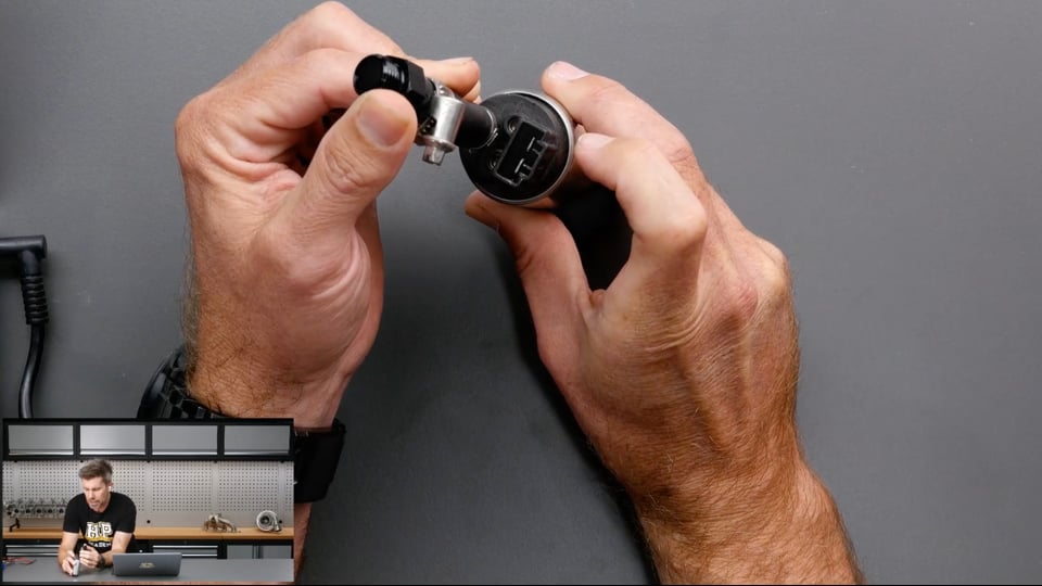
| 30:09 | Now if you are running coil on plug, so you're going to have a coil, might look something like this, we'll get this under our overhead. |
| 30:18 | This is just a Toyota coil. |
| 30:20 | This makes it a little bit trickier because obviously you've got no easy access to something you can get that inductive clamp around. |
| 30:28 | In some instances, actually clamping it around the low voltage wiring can actually be sufficient but particularly if you're testing for spark, I would not use that as a guarantee. |
| 30:39 | What we can do though is, temporarily take a random ignition lead, if you've been working on cars you'll probably have something like this lying around. |
| 30:49 | And by disassembling the ignition coil, normally I'd take this rubber boot off but I won't do this on camera. |
| 30:56 | And we can fit this basically up inside the coil so it's going to contact the inside of the coil just where the end of the spark plug would. |
| 31:06 | So what I've done there will not work, it's going to be spaced way too far apart so it is important to remove that rubber boot, get the ignition lead in there, we can then put the end of the ignition lead onto our spark plug and that then gives us a place where we can easily connect our timing light. |
| 31:21 | So there's always ways around this. |
| 31:24 | Now the other way of doing this which is quicker, arguably quicker, definitely it's without fail and it's a little bit dirtier way of doing it is to simply temporarily remove one of your coils or one of your ignition leads, connect it to a spare spark plug that you've got and then earth that out on something metal in the engine bay. |
| 31:47 | So basically what we'll do is we'll click that in and if we had our bench here, let's say that's the rocker cover, it's really really important if you don't want an electric shock to make sure that the end of that is earthed and then we'll be able to visually watch the plug gap and we'll see if we aren't getting spark. |
| 32:06 | So again that just rules out any problems with the way our inductive timing light has been connected or anything of that nature and we'll visibly be able to see, guaratee that we are getting spark. |
| 32:19 | Worth mentioning here as well that our ECUs will also have test functions. |
| 32:25 | So we can do this for just about anything that I've talked about so far. |
| 32:28 | Let's just jump across to my laptop software for a moment. |
| 32:31 | This happens to be a Link G4+ calibration but again, doesn't matter what your ECU is so if we go to our auxiliary output, so we've talked about fuel pump, let's have a quick look at that. |
| 32:45 | I'll click on that and our fuel pump there, we've got our function up the top, so what we can do in the Link G4+ software, again every ECU will be a little bit different. |
| 32:54 | We click on this, we've got the ability to test this and we can do it in two ways. |
| 32:58 | We can test it in the on position, so that will drive that output permanently to ground as long as this is in the on position and it should run our fuel pump. |
| 33:07 | Now the beauty of this is we can do it without having to crank the engine and in most instances we'll straight away be able to hear the pump running so very easy to test it. |
| 33:16 | Likewise, and we'll talk about this in a little bit, we can use a pulse width modulated test which will be useful for some of the outputs that we may want to test like idle speed control solenoids or maybe boost control solenoids. |
| 33:29 | So really good way of just highlighting in software straight away that that is actually working. |
| 33:36 | And we also can set up our ignition system to do the same. |
| 33:40 | If we go to ignition test we can basically function each of our coils individually, same with the injectors so that just allows us to test each of those outputs without actually having to crank the engine. |
| 33:52 | This is something that I do as part of my ECU tuning process though so we should have already basically gone through this but again we can't guarantee when we're taking a car in that's been set up by other people, that that has been done correctly but really quick way of going through and testing everything. |
| 34:11 | What I will mention, if you're doing an injector test, and the engine's sitting stationary, you really want to make sure that there's no residual fuel pressure in the fuel system because otherwise what you can end up doing, particularly if we run that injector test for an extended period of time, you can end up with a lot of fuel making its way into the cylinders, obviously that's not ideal. |
| 34:35 | Alright we'll carry on with our spark. |
| 34:38 | So obviously if we get a situation where we've got no spark occurring after we've done our first test, either with the inductive light or with the earthed out spark plug, then we need to dive a little bit deeper and a lot of this really comes back to the same things we looked at with our fuel system, check the ECU is actually powered up or powering up and also make sure that the signal to the coil or to the igniter module if you've got an external igniter module is actually working, basically make sure that that is pulsing. |
| 35:13 | So that is again where using our LED test light is really beneficial. |
| 35:18 | So if we jump across to my laptop screen, this is a generic external igniter module that Haltech have as a wiring diagram, so we've got our single coil here. |
| 35:30 | And basically we've got our igniter module, how that works is that the ECU will output, in this case ignition one to a terminal on the igniter module and this works as almost you could think of it a bit like a relay for your coil. |
| 35:47 | So it's providing power and earth to the coil, or it's got permanent power, it's pulsing the earth to charge the coil and then to discharge it when we want the spark event to occur. |
| 35:57 | So what we can do is basically test with our LED test light the wire that's going to the igniter module there and make sure that we are actually seeing our LED test light pulse when we crank the engine over. |
| 36:14 | That will prove that we've got an output from the ECU. |
| 36:16 | Now if we've got an output from the ECU to the igniter module, or straight to the coil in the case of a smart coil like this one, these have built in igniter modules which is pretty common these days. |
| 36:29 | Then either the igniter module or the coil is the most likely culprit so that kind of just gives us a bit of a path to go down in order to try and find out where the faulty module actually happens to be. |
| 36:43 | Now if everything there looks OK though and we do have spark but we've still got the engine not running and we've already gone through and we've figured out that yes we do in fact have fuel, then we also may have a situation where the timing is incorrect. |
| 37:01 | Basically the spark's occurring but it's happening at the wrong point in the engine cycle and that again is where our inductive timing light comes in because we can use this, we can point that at our crank pulley and actually physically see where abouts the timing is and there's a couple of things that we're looking for. |
| 37:18 | First of all, is it in the right place? Now our ECU should be telling us what the timing is but if we don't have any clue or maybe it's a factory ECU where we don't have access to that data live, we're probably going to see the timing at cranking speed, somewhere between about 0 and maybe 15 or 20 degrees, there or there abouts, probably going to be in about the right position. |
| 37:41 | However because there are two full engine revolutions in a single engine cycle, one of the really common traps is that we have the spark occurring at what looks like the right point but it's actually happening on the wrong stroke. |
| 37:56 | So instead of happening as we're coming up on the compression stroke towards top dead centre, it's happening as we're coming up on the exhaust stroke towards top dead centre, forcing out the burned fuel and air. |
| 38:10 | Actually it would be unburned fuel and air because we haven't had an ignition event occur at the right point. |
| 38:15 | So when that happens what we're going to have is maybe some light popping through the exhaust and the engine just won't go and it really can be quite frustrating, particularly if you're looking at the timing mark and everything looks like it's lining up and the reality is there we could just be one full engine revolution or 360° out. |
| 38:34 | So that's always something to be mindful of. |
| 38:39 | The other thing is is the timing consistent? And what I mean by this, is it jumping around or is it always happening every time at the correct point. |
| 38:48 | You're always going to see at cranking RPM, a little bit of variation in the timing, it might move around by maybe 3-5°, that should be at worst but if you're starting to see the spark event, like the timing, sorry the flash of the timing light and the timing looks right on one cycle and then it disappears for a while or it's 60 or 80° advanced and then it's all over the place, that would indicate a couple of potential problems. |
| 39:15 | One of these would be that potentially the ECU is set up with the incorrect trigger mode for your engine. |
| 39:22 | Basically it's getting confused about the engine RPM and position and it's firing the spark at the wrong point or alternatively we could be suffering from some interference, that would be pretty uncommon at cranking RPM in my experience but it is a potential issue there so something to keep in mind. |
| 39:42 | Going one step back as well, I missed this out, if we've got a signal to our coil and our igniter of course we also want to make sure that we've got 12 volts and a solid ground to the coil and igniter as well and again our trusty digital voltmeter is going to be helpful in letting us work that out. |
| 40:04 | Last one there on our list is compression, again non electrical but definitely something that may be a problem. |
| 40:13 | You should be able to hear the compression of the engine based on the variability of the engine speed as it goes through and cranks. |
| 40:22 | When you get a bit sensitive to this, I've developed an ear now where I can kind of hear if one cylinder is potentially a little bit low on compression as well because rather than a nice even cranking speed, you'll hear it sort of speed up and slow down momentarily or speed up on the cylinder that's on the compression stroke that has low compression because it's easier to turn over. |
| 40:44 | We can also check our compression using a compression tester or a leak down tester. |
| 40:50 | That would be a last resort because again we should be able to hear if we've got some level of compression. |
| 40:57 | A couple of examples of where we would be running an engine with no compression, or that I've come across engines with no compression, one which was quite an unusual one, an SR20DE that was running really really poorly initially and then just wouldn't start at all. |
| 41:15 | Looked like it had never had an oil change in its life because of the way the cam lobes in the SR20 are lubricated, there's a little oiling rail that runs across both of the cam lobes in the cylinder head, both of the cams I should say in the cylinder head. |
| 41:29 | And it drips oil onto the cam lobes. |
| 41:31 | That had essentially choked up because it was so full of carbon and gunge basically and it stopped oiling the cam lobes and over the course of the next 1000 or 1500 kilometres, however long it took, it literally wore the cam lobes down to nothing. |
| 41:48 | Obviously you'd like to think that our vehicles are being maintained a little better than this but just to show you some of the extremes. |
| 41:55 | Another one, if we've got a mechanical lifter arrangement or a mechanical rocker arrangement, then lash may be incorrectly set and we may have negative lash meaning that the valves are actually being held off their seats, of course the other one would be a piston that's severely melted or something of that nature but in that instance we're probably only going to have maybe one cylinder that's being affected by that so we probably would still get the engine to run, it would only just be running on 3 cylinders. |
| 42:24 | Running on 3 cylinders as well, I'll just mention, actually no I'll come into that in a second, the very next one. |
| 42:33 | So yeah just to recap there, starting by understanding what's been done to the vehicle, what's been done to the engine since the last time it ran and then going through that checklist for our fuel, our air, our spark and our compression. |
| 42:46 | So that covers our first and easily the most common problem that I see. |
| 42:51 | Moving on, the next one is not running on a single cylinder, so nice segue from what I was just talking about there. |
| 42:58 | So basically we want to start with that above list and go through everything because it could be one of those problems, just basically narrowed down to a single cylinder. |
| 43:08 | We also want to find out which cylinder the problem is existing on so if we've got some data, an exhaust gas temperature sensor or individual cylinder lambda, that's going to really quickly allow us to figure out which cylinder the issue exists on. |
| 43:22 | Most probably won't have that data so really easy way is just to individually at idle, disconnect the injector plugs from each cylinder one at a time and obviously when you get to the cylinder that's not running, you're going to have no change in engine speed or note. |
| 43:37 | With this sort of situation, I would start by checking that the engine is mechanically OK. |
| 43:43 | Then also checking the individual cylinder coil and the injector, basically everything that we just talked about, making sure that that's OK. |
| 43:52 | And then the other one which has caught out a few people including myself at one point, is there anything weird going on inside the ECU in terms of weird trims or something that are in place. |
| 44:05 | Now the issue I had was actually on a Mitsubishi EVO 8 and it was running a MoTeC M800 plug and play and there was an error in MoTeC's plug and play base map, for all I know it might actually still exist. |
| 44:18 | It was a very weird one to find. |
| 44:20 | Basically what happened, above 2 bar of boost it trimmed all of the fuel out of number 3 cylinder. |
| 44:28 | Up until 2 bar of boost it was absolutely fine and basically then the higher the boost went, the more fuel was removed. |
| 44:34 | Obviously not a great scenario as well in a position at high boost where you want fuel. |
| 44:40 | But everything was fine with that engine, obviously when we're running below 2 bar of boost and then we ended up doing a race gas or C16, Q16 tune on it and we wound the boost up and as soon as we went above 2 bar, it started developing this misfire and also it wasn't just boost, it was also RPM I think it only occurred above 8000 RPM so it was quite frustrating to find and this is really one of those aspects that comes back to the fundamentals of what we teach in our EFI tuning courses is never assume that a base map, even one supplied by a manufacturer is on point. |
| 45:17 | The number of times I've seen small discrepancies, usually much less significant than that but small discrepancies that can cause little headaches down the track, it's more common that you would think. |
| 45:31 | Third problem and this is really really common is an engine that's running lean under high RPM and load. |
| 45:39 | Quite often we'll see this on the dyno and the scenario might pan out where we start tuning a turbocharged engine from wastegate boost and at that point everything might be absolutely fine and we're running the engine out let's say to 7000 RPM. |
| 45:52 | And as we step up the boost, what we might find is that we start to see the air/fuel ratio move a little bit lean as the RPM comes up. |
| 46:00 | So of course we jump into our fuel map and we add a little bit more fuel there, do another run, doesn't really have any effect and over time we get to a position where our injectors are at maximum duty cycle and we still don't have enough fuel. |
| 46:13 | Now there can be a variety of causes for this. |
| 46:17 | Obviously injectors that are too small, that's going to do it but the scenario where we still have injector duty cycle available but we add pulse width to the injector and it doesn't actually add any more fuel, that points to a fuel supply issue. |
| 46:31 | So of course the next obvious problem is we may have a fuel pump that's simply too small for the application but the wiring to the fuel pump is something that is really easy to overlook. |
| 46:44 | So assuming that our parts are in fact up to the task, we really want to check what's happening with our fuel pump. |
| 46:51 | Now again this is where our trusty fuel pressure gauge comes in handy and even in vehicles that didn't have permanently mounted fuel pressure sensors or gauges, I always had a simple test rig set up in our dyno that I could temporarily plug onto a car and check the fuel pressure. |
| 47:10 | So what you'd see in that scenario is the fuel pressure would initially come up to where it's supposed to be and then as the RPM and the boost climbs, the fuel pressure will start to sort of drop away and obviously that's where we're trying to accommodate the required fuel flow by increasing the injector duty cycle but there's a limit to what we can do here. |
| 47:29 | Quite often what we will find though is it's not a result of a fuel pump that's too small but simply a fuel pump that's not receiving the full 14 volts when the engine is running. |
| 47:39 | Now if you look at the flow versus fuel pump voltage which any fuel pump manufacturer will have, you'll see that of course as the voltage to the pump drops away, so does the fuel flow so that's the problem we're seeing there. |
| 47:55 | So why is this the case? There could be a number of reasons for this. |
| 48:00 | Particularly if you are still dealing with the factory wiring and particularly if you have upgraded to a pump that's going to draw more current because it's flowing more fuel, the factory wiring may simply not be up to task and we can end up with quite a large voltage drop when we actually measure it at the pump. |
| 48:16 | So that's where we're using our multimeter to physically measure across those two terminals at the pump or the connector where it goes into the fuel pump cradle. |
| 48:26 | So again of course we should be seeing about 14 volts, give or take about 0.2, 0.3. |
| 48:31 | What you'll often find in this scenario is we might start out a little low, maybe 13.5, maybe 13.2 volts and as the load increases on the pump and it's working harder, we start to see that voltage drop away and it might get down to 11, 11.5 volts by high RPM, near the end of our ramp run. |
| 48:51 | So this could be a case of our wiring not being adequate, the factory wiring simply not being up to task. |
| 48:59 | Other aspects to consider there is a lot of modern vehicles have a fuel pump speed controller in the system which can vary the voltage essentially the pump's getting. |
| 49:11 | If you don't understand that and it's not being controlled, that could be your issue. |
| 49:14 | The other problem I often see is the factory earth to the pump is not sufficient so very common modification we make to the wiring to the fuel pumps is basically to use the factory wiring to actuate a relay and then we run battery voltage direct though a fuse, back to the relay and to our fuel pump and then rewire the earth, making sure that we are getting full 14 volts when the fuel pump is running. |
| 49:41 | Right, problem number 4 is sensor malfunction and basically this comes down to any of the sensors on the engine, if they are lying to the ECU, this can cause all sorts of running issues. |
| 49:54 | Let's say for example an air temperature sensor, that's used by the ECU to adjust the fuelling as required. |
| 50:03 | Now most ECUs will have a fault mode, if the circuit goes basically to ground or to open circuit which would be 5 volts being measured by the ECU, then the ECU will default to some default value that you can set, maybe 30° for example. |
| 50:21 | But that's not always the case and maybe those settings have been fumbled. |
| 50:24 | So basically making sure that our sensors are working correctly is important. |
| 50:29 | So first of all, understanding how the sensor works is really the key to this. |
| 50:34 | So we've got two main sensors that we see on our engines. |
| 50:38 | The first of these is an analog voltage sensor like this fuel pressure sensor here. |
| 50:45 | These come in a variety of different shapes and sizes but really the key to it, which hopefully you can see in there, it is a little bit tricky, they've got 3 terminals in there and the way these work is that they require a regulated 5 volt supply from the ECU. |
| 51:00 | They also require a sensor 0 volt. |
| 51:03 | So basically that's a regulated 5 volts between those two pins and then they'll output a variable voltage between 0 and 5 volts back to the ECU that corresponds to the fuel pressure, oil pressure, manifold pressure, throttle position or whatever so this is a very common sensor that we see on our engines. |
| 51:22 | The other type of sensor that we will also have is a 2 wire negative temperature coefficient thermistor like this one here, this is a Delphi air temp sensor. |
| 51:33 | And how these work is a little bit different. |
| 51:36 | They are, as I mentioned, two wire and these will have one connection that goes to a sensor 0 volt on the ECU and the other one will go to a dedicated analog temperature input pin. |
| 51:48 | The key with the analog temperature input pin is that the way this works is it has an internal pull up resistor inside of the ECU that goes to the 5 volt rail so basically it creates a little voltage divider circuit and that's why we only need 2 wires going out to the air temperature sensor. |
| 52:06 | Now how these fail, so with our temperature sensor, if the wiring fails or something fails, and this goes open circuit, what we're going to end up with is the ECU measuring 5 volts because basically the pin is disconnected at the ECU header so it's just going internally to that 5 volt rail via the pull up resistor. |
| 52:29 | So this is a clue because if we are looking at our ECU control software and we see that that particular input's sitting at 5 volts, that's a pretty clear sign that either the sensor has failed or it's gone open circuit. |
| 52:43 | The other way that it could fail is to go closed circuit straight to 0 volts, our sensor ground, obviously we'd see 0 volts there but that's a really quick thing to check. |
| 52:55 | On the other hand, with our analog voltage input there, if the sensor fails, it could fail, most often it's going to fail in an open circuit mode which the ECU will then read 0 volts. |
| 53:09 | There's a possibility that it could fail with a short circuit to the 5 volt rail but very very uncommon. |
| 53:16 | So just understanding how those two sensors work and particularly the 5 volt pull up resistor or the pull up resistor to 5 volts with the analog temp sensor is really important. |
| 53:28 | Alright so first to test or fault find one of these is to physically check the connector and make sure that the wiring is intact, maybe it's a poor crimp and the crimp, the wire is simply pulled out of the crimp, it's also possible if someone has been working on the car and has been a bit rough with handling one of the connectors, that they've physically pulled a wire out of the connector, so that's the very first thing to check. |
| 53:53 | Then we can check at the connector using our multi meter and make sure that we've got 0 and 5 volts on the appropriate pins, obviously if we've got an analog voltage input, or for our temperature sensor make sure that we've got 0 volts at the appropriate pin. |
| 54:12 | That 0 volt, it's a sensor 0 volt, sensor ground depending on what the ECU manufacturer calls it. |
| 54:19 | So it is different to the power ground but it will still have continuity to ground so you can check using the continuity function on your multimeter, actually I'll show you that now. |
| 54:31 | And make sure that that's the case. |
| 54:33 | So our continuity, if we go over here we've got our ability to measure resistance and if we go all the way down to this point here, this is our continuity check and that will give us a nice little beep when we connect these together. |
| 54:50 | And we can audibly hear that, that means that means that we've got continuity so basically if we went between the 0 volt terminal in our connector and to maybe the cylinder head or some clean alloy or metal on the engine, we should get continuity there. |
| 55:07 | If that all checks out, or if that doesn't check out I should say actually, we want to also check our continuity back to the ECU terminals. |
| 55:15 | All of the 0 volt and 5 volt are normally common. |
| 55:19 | So what this means is that we can check between all of our sensors inside of the engine bay harness. |
| 55:26 | If we go between two of the 5 volt, we should have continuity there. |
| 55:29 | We can then also as I mentioned, check continuity from the connector in the engine bay back to our ECU header plug and that's where I earlier mentioned that we can use a little jumper pin just to get access into our ECU header plug and give us something nice and easy to get our multimeter on. |
| 55:49 | Just makes that process of continuity testing much much easier. |
| 55:54 | Also, obviously we don't have a lot of length in the leads on our mutlimeter. |
| 56:00 | Generally I'll make up a temporary jumper wire that I can run, maybe it's a couple of metres long that I can run into the engine bay, maybe I'll end up crimping a terminal like this in the engine bay side as well and that just again makes it nice and easy to back probe into those connector plugs and make sure that we're doing our continuity test. |
| 56:20 | So if all of that checks out, basically we've got continuity back to the ECU, we've got the 5 volt and 0 volt present on the analog voltage signal, we've got our analog voltage input coming back to the correct terminal on the ECU with good continuity, same with our temperature sensor, that would be a pretty good indication that the fault is actually with our sensor and I would change that out for a spare one. |
| 56:48 | Normally as well when you're working on cars like this, you're going to end up collecting a bunch of spares so it's normally not a big deal for common sensors like our manifold pressure, fuel pressure or temperature sensors just to momentarily plug in a spare that we've got lying around and physically see if that actually fixes the issue. |
| 57:07 | The 5th fault that we'll go over here is an output actuator no go situation. |
| 57:18 | So output actuators, these could be just about anything, maybe a boost control solenoid. |
| 57:27 | We've got one of those here, so this is obviously pulsed in order to control our boost and the other one I've got here is the Nissan VVL solenoid from our SR20 so that is used to switch the, let's try and get those actually under the overhead camera, that's used to switch from the low cam lobe to the high cam lobe on our Nissan SR20VE engine. |
| 57:52 | Basically again, a good understanding of how these work is really key to fault finding them. |
| 57:57 | Output actuators that are simple like this that are just switched or pulse width modulated, we'll end up with 12 volts being connected to 1 side and the ECU will normally ground the other side via an auxiliary output. |
| 58:11 | So key to that of course is do we have 12 volts going to these circuits? Depending on how the ECU has been wired, these could come from an auxiliary relay, maybe something that is separate to the relay that's providing power to the ECU so we want to make sure that we've got 12 volts to one side of it and then we can do our test output on our ECU which I showed you earlier and make sure that the output is physically functioning. |
| 58:41 | Now again it sort of comes down to wiring continuity tests back to the ECU, making sure that our wiring is intact and making sure that we are actually providing the output function that we expect. |
| 58:53 | Again with anything that is switched or pulse width modulated, a really good way of seeing that is operating is with our LED test light. |
| 59:02 | As I mentioned, you do need to just be a little bit mindful, if the frequency is very high, then you're not likely to see that LED flashing. |
| 59:12 | That also brings me to another set up problem that can be an issue with the likes of our boost control solenoid here. |
| 59:19 | These are designed to work at relatively low frequencies. |
| 59:22 | I will generally end up with them running at somewhere between about 20 and 30 Hz. |
| 59:27 | If you set these up at a much higher frequency, maybe 150 Hz or above, physically the mechanism inside the solenoid cannot operate that quickly and it just won't do anything. |
| 59:41 | And again if we just come back across to my laptop software here, again every ECU will have a way of doing this but if we come down, and I don't actually have, oh no I do have a boost solenoid here. |
| 59:53 | So you can see we've got this set up at 20 Hz but if you go and set this up to basically pulse width modulate it in a test mode, so that'll function it continuously. |
| 01:00:05 | And then you can actually change this frequency here. |
| 01:00:08 | And if you set this frequency up too high, you'll get to a point you'll be able to audibly hear the solenoid sort of buzzing and when you go too high it will just simply stop and you won't hear any noise out of it and that is a good indication that you've gone too far in the frequency there so something just to keep an eye on with your pulse width modulated outputs. |
| 01:00:32 | Alright we're going to move into questions really shortly. |
| 01:00:36 | Bit of a long one there so hopefully we do have some questions or hopefully you've understood everything. |
| 01:00:42 | Our last element that I wanted to talk about here is grounding and this is a really big problem, we see so many issues with grounding problems and this can manifest itself in all manner of problems including basically an engine that's very inconsistent and difficult to tune up, sensors that are basically reporting nonsense and just about anything in between. |
| 01:01:07 | So there are 2 grounding elements with our ECU, one is our power ground and the other is our sensor ground which I've already touched on. |
| 01:01:14 | It's really important to understand the principle of our star point earthing. |
| 01:01:19 | Which basically means that all of our earthing needs to be at one common point and generally we'll make that on the engine block. |
| 01:01:26 | So how that works is if we start from our battery, we're going to have our battery with a negative terminal on it. |
| 01:01:32 | Normally we will run a relatively short ground strap between the battery negative and a clean point on the vehicle's chassis. |
| 01:01:42 | Normally using the chassis as a common grounding point is more than sufficient because there's essentially no resistance in the chassis itself. |
| 01:01:51 | Then when we get to the engine, we're going to run another ground strap that will go from the chassis to the engine. |
| 01:01:57 | One of the real key points here is to make sure that we don't have any rust or paint or anything between these earth points, that will just serve to increase the resistance and we don't want that. |
| 01:02:09 | Then we have our ECU grounds which as I said, those are run through the firewall and these should be earthed on the engine block. |
| 01:02:18 | Sensors should not be earthed to the engine block or the cylinder head. |
| 01:02:24 | These need to go to the dedicated sensor 0 volt wires or pins on your ECU header plug. |
| 01:02:31 | There will, as I mentioned before, be continuity to the power ground as well but the reason that's so important is that we're talking about a very very small difference in voltage, making a difference to whatever you're measuring, fuel pressure, oil pressure, manifold pressure. |
| 01:02:52 | And if we run the sensor ground straight to the engine block or the head it will actually read, it will work but we open ourselves up to the potential for ground offsets which can influence the accuracy of the sensor. |
| 01:03:05 | So always make sure that those are wired to the appropriate sensor 0 volt pin. |
| 01:03:12 | Coil grounds as well, igniter ground, these need to be run to the engine block or the cylinder head and we want to make sure that those runs are really small, as small as we possibly can. |
| 01:03:25 | So one of the things that we quite often see when a vehicle's being worked on is maybe a ground has been left off inadvertently and even with modern factory vehicles, we're most likely going to find multiple ground points on the cylinder head and the engine block so we need to make sure very carefully that all of those have been reinstated correctly. |
| 01:03:47 | The other aspect there is it's possible if someone's been a little bit rough or maybe the wiring crimping hasn't been done correctly, that a wire or several wires have pulled out of one of those so always worth checking. |
| 01:04:00 | Alright that's brought us to the end there and that's probably one of our longer webinars. |
| 01:04:08 | There's a lot to it and obviously I really have just scratched the surface there of what potentially we could have problems with but hopefully just sharing my experience there on what I've seen, that's going to help you when it comes to your own testing. |
| 01:04:25 | Looks like we have no questions there so obviously that's going to mean I've done a great job of explaining things. |
| 01:04:31 | Of course for our members if you do have questions at a later point, if you're watching this maybe in our webinar archive and you've got questions, please feel free to ask those on the forum and I'll be happy to answer them there. |
| 01:04:43 | Thanks for watching and look forward to seeing everyone next time. |
Timestamps
0:00 - Introduction
0:55 - You can't fix every problem with a laptop
1:41 - Diagnostic equipment
6:00 - Engine won't start
10:59 - Engine won't start | Check fuel
27:48 - Engine won't start | Check air
28:42 - Engine won't start | Check spark
40:04 - Engine won't start | Check compression
42:51 - Not running on a single cylinder
45:31 - Running lean
49:42 - Sensor malfunction
57:09 - Output actuator no go
1:00:32 - Grounding


