One of the most powerful things about CAN bus as a communication protocol is that it's largely brand-agnostic. Your ECU, dash, PDM, and TCU don't all need to come from the same manufacturer to work together on the same network. As long as each device is sending and receiving messages in a format the others understand, you can combine devices from different manufacturers freely.
While that all works well in theory, but in practice you'll hit a wall: your ECU broadcasts data at one arbitration ID in one format, and the device you're connecting to expects it somewhere else entirely. A CAN bus gateway is what sits in the middle and bridges that gap. The CAN Triple from Minton Performance is a three-channel gateway built specifically for that job, giving you complete, programmable control over message routing across up to three independent CAN networks simultaneously.
In this article: What Is the CAN Triple? | Who Is It For? | What Do You Need to Get Started? | How Does It Work? | A Real-World Use Case | Conclusion

What Is the CAN Triple?
The CAN Triple is a compact, three-channel CAN bus gateway and router programmed in C, built around an STM32 microcontroller and designed specifically for automotive and industrial research and development environments. Mitch Minton of Minton Performance built it out of frustration with the options available on the market, finding that existing solutions either lacked the control he needed or imposed timing restrictions that prevented efficient integration work. The project is fully open source, with all code and documentation available on the Minton Performance GitHub repository.
"I got frustrated with the options available on the market that didn't offer complete control and if they did say they offered complete control they didn't have timing that would allow me to do things as efficiently as I wanted to do them" - Mitch Minton
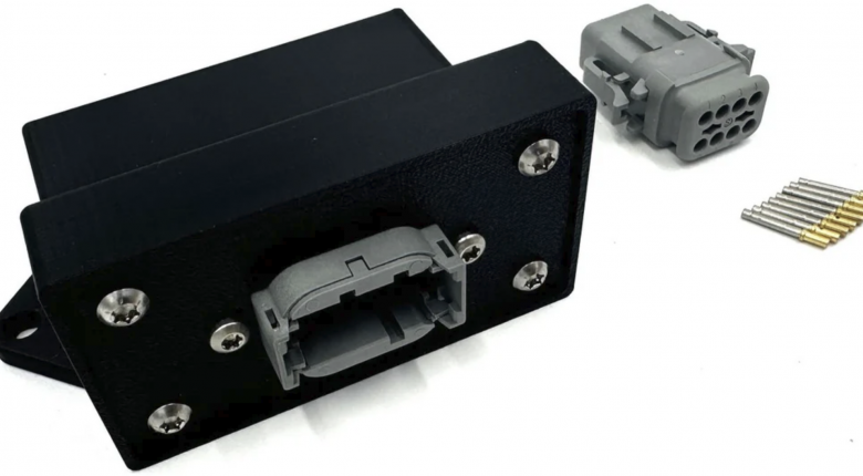
All three CAN buses on the CAN Triple are independently routed and managed, meaning traffic on each bus is handled separately and the user defines exactly what happens to every message that passes through. The hardware accepts an input voltage of 6 to 32V and is reverse polarity protected, with a nominal current draw of 0.07 amps. The board ships in a plastic housing and connects via an 8-pin DTM06-8SA connector, with CAN High and CAN Low for each of the three buses on the signal pins alongside power and ground.
Five onboard LEDs give you at-a-glance system status. A power LED confirms the device has supply voltage. A general-purpose LED can be toggled or controlled via code for testing and debugging. The remaining three LEDs indicate whether the software-controlled 120-ohm termination resistor is active or inactive on each of the three buses independently, so you always know the termination state of each network without having to probe the harness.
The CAN Triple operates on CAN 2.0 networks only. On his YouTube channel, Mitch has noted that he intends to build on the platform further over time, so check the latest Minton Performance documentation for the current hardware capability.
Who Is It For?
The CAN Triple is built for tuners and engineers who need a programmable solution for managing CAN bus communication between devices that don't natively speak to each other. This covers two broad scenarios. The first is aftermarket-to-aftermarket integration, where you're mixing electronics from different manufacturers and one device's output format doesn't match what another is expecting. The second is aftermarket-to-OEM integration, where you're replacing a factory ECU with a standalone unit but the rest of the vehicle's electronics are still expecting messages in the OEM format at the OEM addresses. Both are solvable with the CAN Triple, provided you understand what the network needs to see and are willing to write the code to make it happen.
It's also useful for consolidating traffic from multiple CAN networks running at different speeds into a single unified bus. If you have two networks running at different bitrates and you want all of that data visible on one bus for logging purposes, the CAN Triple handles the bridging. Each bus can be set to an independent bitrate of up to 1 Mbit/s.
This is not a plug-and-play device. It requires you to write C code to define the behaviour you need, and you need a clear understanding of what the gateway should do before you start. If you're already familiar with CAN concepts such as arbitration IDs, data length codes, bitrates, and termination, the development environment is approachable. If you're starting from scratch on CAN Bus, this is a great watch to begin to understand what it's all about.

What Do You Need to Get Started?
Programming the CAN Triple requires a handful of free software tools installed on your computer, plus an STLINK-V3MINIE or compatible SWD debugger for uploading code to the board. The CAN Triple is available from Minton Performance with or without a programmer included.
The software prerequisites are as follows:
- Python, available from python.org. When installing, make sure to tick the option to add Python to PATH.
- Visual Studio Code (VS Code), the development environment where you'll write and manage your code.
- PlatformIO extension for VS Code, installed from within VS Code's extension marketplace. PlatformIO manages the build toolchain for embedded targets.
- STM32 platform framework, installed from within PlatformIO. This provides the compiler and hardware support for the STM32 microcontroller on the CAN Triple.
- The CAN Triple base project, downloaded as a ZIP from the Minton Performance GitHub repository and opened in VS Code. PlatformIO initialises the project automatically on first open.
Once the project is open, all user-facing code is written in the user_code.c file. You don't need to touch the underlying firmware. All configuration, message handling logic, and timed functions are defined here. The GitHub repository also includes a Code Generator Tools folder with a Unified DBC to C Code tool to assist with converting DBC file content into ready-to-use code.
How Does It Work?
Configuration starts with setting up each bus individually. For each of the three CAN buses, you define the bitrate, whether the software termination resistor is active, and whether the bus runs in normal mode or listen-only (silent) mode. Buses can be set to different bitrates independently, so you could run CAN 1 at 500 kbit/s, CAN 2 at 250 kbit/s, and CAN 3 at 1 Mbit/s if your application calls for it.
When a message is received on any bus, it's handled by the onReceive function, which is called automatically each time a new CAN message arrives. Inside onReceive, you work with a CAN message struct that gives you access to five pieces of information about each incoming message: which bus it arrived on, whether it uses a standard or extended ID, the arbitration ID, the data length code, and the data payload of up to 8 bytes. Using these fields, you write logic to decide what to do with each message. You can route it to another bus unchanged, decode a signal value from the data bytes, re-encode it into a different format, and transmit it out on a different bus at a different arbitration ID. Each bus has its own transmit queue holding up to 256 messages, so the device handles traffic bursts without dropping data.
One practical consideration when assigning arbitration IDs to outgoing messages is priority. On a CAN bus, if two messages attempt to transmit simultaneously, the one with the lower arbitration ID wins and gets sent first. When programming the gateway, it's good practice to assign your most time-critical messages the lowest arbitration IDs and work upward by priority. A gear shift command should have precedence over an air temperature update, for example.
The framework also provides timed event functions at a range of intervals from 1 Hz through to 2000 Hz, where you can place code that needs to execute on a regular schedule rather than only in response to received messages. This is where periodic transmissions belong, such as sending a heartbeat message out on a bus at a fixed rate.
For decoding signal values from incoming data, the firmware includes helper functions covering floats, signed integers, unsigned integers, and raw bitmask operations. For more advanced work, a dbc_decode function takes DBC file parameters directly, including start bit, bit length, endianness, factor, and offset, and returns the decoded signal value. A matching dbc_encode function takes a scaled signal value and packs it into a CAN message data array ready for transmission. These handle the bit manipulation involved in working with signals that don't fall neatly on byte boundaries.
A Real-World Use Case
A strong example of the CAN Triple in action is a project Mitch completed in collaboration with Tuned By Shawn (featured in HPA Tuned In Podcast: 145: How to Avoid Wasting Thousands on the Dyno), producing a Haltech plug-and-play solution for the C6 Z06 Corvette. On paper, fitting a Haltech ECU to this platform should be straightforward. In practice, the Haltech's CAN communication template is not user-definable in terms of message addresses. The OEM electronics in the Corvette are expecting messages in a specific format at specific arbitration IDs, and the Haltech has no provision to change where it puts that data on the network. Without intervention, the factory cluster and other OEM electronics would not receive what they're expecting.
The CAN Triple solves this by sitting between the Haltech and the rest of the vehicle's network. It reads the messages the Haltech is transmitting, decodes the signal values it needs, and re-transmits them at the arbitration IDs and in the data format the OEM systems expect. The result is a vehicle where the factory cluster, ABS, HVAC, transmission-related displays, and other chassis functions continue to operate correctly, while traction control is handled through the Haltech system. If an edge case surfaces down the road that reveals a missing message, it can simply be added to the gateway code without requiring any changes to the Haltech calibration itself.
A second common application is data logging across multiple networks. If you have two CAN buses running at different bitrates and want all of that traffic captured in a single logging session, you can bridge both onto a third bus running at whatever bitrate your logger supports. Rather than logging each network separately and merging files afterwards, everything arrives on one bus in a unified stream. A third bus can also be run in listen-only mode to capture traffic on a production vehicle network without injecting any messages onto it, which is useful for reverse engineering or diagnostics work where you need to observe without interfering.

Conclusion
The CAN Triple from Minton Performance is a well-considered tool for anyone who has run into the limitations of off-the-shelf CAN integration options, whether that's mixing aftermarket electronics from different manufacturers or integrating a standalone ECU into a platform that still relies on OEM CAN-dependent systems. It gives you genuine, low-level control over three independent CAN buses simultaneously, with configurable bitrates, software-controlled termination, and a C-based development framework that keeps the ceiling high for what's achievable.
If you want to build your understanding of CAN bus from the ground up before tackling a project like this, the CAN Bus Communications Decoded Course is the place to start.